EP0577873B1 - Réfractaire pour l'injection de gaz dans une enceinte d'affinage de métal liquide - Google Patents
Réfractaire pour l'injection de gaz dans une enceinte d'affinage de métal liquide Download PDFInfo
- Publication number
- EP0577873B1 EP0577873B1 EP92111533A EP92111533A EP0577873B1 EP 0577873 B1 EP0577873 B1 EP 0577873B1 EP 92111533 A EP92111533 A EP 92111533A EP 92111533 A EP92111533 A EP 92111533A EP 0577873 B1 EP0577873 B1 EP 0577873B1
- Authority
- EP
- European Patent Office
- Prior art keywords
- gas
- refractory
- molten metal
- gas blowing
- permeable portion
- Prior art date
- Legal status (The legal status is an assumption and is not a legal conclusion. Google has not performed a legal analysis and makes no representation as to the accuracy of the status listed.)
- Expired - Lifetime
Links
Images
Classifications
-
- B—PERFORMING OPERATIONS; TRANSPORTING
- B22—CASTING; POWDER METALLURGY
- B22D—CASTING OF METALS; CASTING OF OTHER SUBSTANCES BY THE SAME PROCESSES OR DEVICES
- B22D1/00—Treatment of fused masses in the ladle or the supply runners before casting
- B22D1/002—Treatment with gases
- B22D1/005—Injection assemblies therefor
-
- C—CHEMISTRY; METALLURGY
- C21—METALLURGY OF IRON
- C21C—PROCESSING OF PIG-IRON, e.g. REFINING, MANUFACTURE OF WROUGHT-IRON OR STEEL; TREATMENT IN MOLTEN STATE OF FERROUS ALLOYS
- C21C7/00—Treating molten ferrous alloys, e.g. steel, not covered by groups C21C1/00 - C21C5/00
- C21C7/04—Removing impurities by adding a treating agent
- C21C7/072—Treatment with gases
-
- C—CHEMISTRY; METALLURGY
- C23—COATING METALLIC MATERIAL; COATING MATERIAL WITH METALLIC MATERIAL; CHEMICAL SURFACE TREATMENT; DIFFUSION TREATMENT OF METALLIC MATERIAL; COATING BY VACUUM EVAPORATION, BY SPUTTERING, BY ION IMPLANTATION OR BY CHEMICAL VAPOUR DEPOSITION, IN GENERAL; INHIBITING CORROSION OF METALLIC MATERIAL OR INCRUSTATION IN GENERAL
- C23C—COATING METALLIC MATERIAL; COATING MATERIAL WITH METALLIC MATERIAL; SURFACE TREATMENT OF METALLIC MATERIAL BY DIFFUSION INTO THE SURFACE, BY CHEMICAL CONVERSION OR SUBSTITUTION; COATING BY VACUUM EVAPORATION, BY SPUTTERING, BY ION IMPLANTATION OR BY CHEMICAL VAPOUR DEPOSITION, IN GENERAL
- C23C30/00—Coating with metallic material characterised only by the composition of the metallic material, i.e. not characterised by the coating process
-
- G—PHYSICS
- G01—MEASURING; TESTING
- G01N—INVESTIGATING OR ANALYSING MATERIALS BY DETERMINING THEIR CHEMICAL OR PHYSICAL PROPERTIES
- G01N33/00—Investigating or analysing materials by specific methods not covered by groups G01N1/00 - G01N31/00
- G01N33/26—Oils; Viscous liquids; Paints; Inks
- G01N33/32—Paints; Inks
Definitions
- the present invention relates to a refractory for gas blowing to be attached to an opening of a molten metal refining vessel as defined in the preamble portion of claim 1.
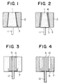
- FIG. 1 is a schematic vertical sectional view illustrating a conventional refractory for gas blowing used as a porous plug, attached to a collar portion of an opening in the bottom wall of a molten metal refining vessel.
- 1 is a porous plug comprising a porous refractory
- 2 is a collar portion comprising a refractory, of an opening provided in the bottom wall of a molten metal refining vessel
- 3 is a mortar joint for jointing the porous plug 1 to the collar portion 2
- 11 is a gas supply pipe.
- FIG. 2 is a schematic vertical sectional view illustrating another conventional refractory for gas blowing used as a porous plug, attached to a collar portion of an opening in the bottom wall of a molten metal refining vessel.
- 1 is a porous plug comprising a porous refractory
- 2 is a collar portion comprising a refractory, of an opening provided in the bottom wall of a molten metal refining vessel
- 4 is a porous sleeve comprising a porous refractory
- 3 and 5 are mortar joints for jointing the porous plug 1 to the porous sleeve 4, and the porous sleeve 4 to the collar portion 2, respectively
- 11 is a gas supply pipe (hereinafter referred to as the "prior art").
- a porous plug 1 comprising a porous refractory, having a short service life, must be frequently replaced. Because the porous plug 1 comprising the porous refractory tends to be easily damaged, furthermore, the operation of attaching the porous plug 1 to a collar portion 2 of an opening of a molten metal refining vessel incidental to the replacement, must be conducted carefully. This leads to a long replacement time of the porous plug 1 and a lower operating rate of the molten metal refining vessel.
- a prior art top blown steel coverter gas stirring plug disclosing the features of the preamble portion of claim 1 and being similar to the refractory of Fig. 3 is described in JP-A-5 903 1808.
- This prior art stirring plug is integrally made from a specific refractory material consisting of C 5-30% and the balance at least one of MgO, Al 2 O 3 , Cr 2 O 3 and ZrO 2 .
- a refractory for gas blowing to be attached to an opening of a molten metal refining vessel which comprises:
- a refractory which comprises a gas permeable portion comprising a non-porous and dense refractory excellent in corrosion resistance, which gas permeable portion has a plurality of gas blowing apertures, on the one hand, and a collar portion comprising a non-porous and dense refractory excellent in corrosion resistance, formed integrally with the gas permeable portion so as to surround the gas permeable portion, on the other hand, it is possible to extend the service life of a molten metal refining vessel and improve the operating rate of the refining vessel.
- Fig. 3 is a schematic vertical sectional view illustrating a refractory for gas blowing similar to the one described in JP-A-5 903 1808, to be attached to an opening of a molten metal refining vessel.
- 6 is a gas permeable portion having a columnar shape
- 7 is a collar portion formed so as to surround the gas permeable portion 6
- 12 is a gas supply pipe.
- the gas permeable portion 6 and the collar portion 7 are integrally formed of refractories having the same chemical composition.
- Each of the plurality of gas blowing apertures 9 has a size sufficient to prevent, after the stoppage of gas blowing, the molten metal received in the refining vessel from flowing out of the refining vessel through the gas blowing apertures 9.
- the refining gas blown through the gas supply pipe 12 for the refractory for gas blowing attached to the opening in the bottom wall of the molten metal refining vessel, is blown through the plurality of gas blowing apertures 9 into molten metal received in the refining vessel.
- Fig. 4 is a schematic vertical sectional view illustrating an embodiment of a refractory for gas blowing of the present invention, to be attached to an opening of a molten metal refining vessel.
- 6 is a gas permeable portion having a columnar shape
- 7 and 8 are collar portions formed so as to surround the gas permeable portion 6
- 12 is a gas supply pipe.
- the gas permeable portion 6 and a part 8 of the collar portion are formed of refractories having the same chemical composition, and the remaining part 7 of the collar portion is formed of a refractory having a chemical composition different from that of the refractories for the gas permeable portion 6 and that portion 8 of the collar portion. Furthermore, the gas permeable portion 6 and the collar portions 7 and 8 are formed integrally with each other.
- Each of the plurality of gas blowing apertures 10 has a size sufficient to prevent, after the stoppage of gas blowing, the molten metal received in the refining vessel from flowing out of the refining vessel through the gas blowing apertures 10.
- the refining gas blown through the gas supply pipe 12 for the refractory for gas blowing attached to the opening in the bottom wall of the molten metal refining vessel, is blown through the plurality of gas blowing apertures 10 into the molten metal received in the refining vessel.
- the gas permeable portion and the collar portion are formed of refractories having different chemical compositions or that part of the collar portion and the remaining part of the collar portion are formed of refractories having different chemical compositions.
- the refractories of the gas permeable portion and the collar portion should contain at least 88 wt.% alumina (Al 2 O 3 ) to ensure a high corrosion resistance, and should be non-porous with a porosity of up to 20% to exhibit a high density.
- Each of the plurality of gas blowing apertures 9 in the form of slits, which run through the gas permeable portion 6 in the axial direction thereof, should have a width of up to 0.25 mm so as to prevent, after the stoppage of gas blowing, the molten metal received in the refining vessel from flowing out of the refining vessel through the gas blowing apertures 9.
- Each of the plurality of gas blowing apertures 10 in the form of circular apertures, which run through the gas permeable portion 6 in the axial direction thereof, should have a diameter of up to 0.6 mm so as to prevent, after the stoppage of gas blowing, the molten metal received in the refining vessel from flowing out of the refining vessel through the gas blowing apertures 10.
- FIG. 3 A sample of the refractory for gas blowing as shown in Fig. 3 (hereinafter referred to as the "sample similar to the invention") No. 1 was prepared, which comprised a gas permeable portion 6 having a columnar shape with a diameter of 105 mm and a height of 360 mm, and a collar portion 7 formed integrally with the gas permeable portion 6 so as to surround the gas permeable portion 6, and had a shape of rectangular parallelepiped with a length of 400 mm, a width of 400 mm and a height of 360 mm.
- gas blowing apertures 9 in the form of slits, which ran through the gas permeable portion 6 in the axial direction thereof, were provided to blow a refining gas.
- Each of the gas blowing apertures 9 had a rectangular cross sectional area of 0.25 mm X 10 mm.
- the gas permeable portion 6 and the collar portion 7 were integrally formed of refractories having the same chemical composition containing 88 wt.% alumina and having a porosity of 10%, as shown in Table 1.
- the other properties of the sample similar to the invention No. 1 were as shown in Table 1.
- the column in Table 1 heading "Gas flow rate” means a flow rate per minute of a refining gas which has passed through the sample similar to the invention No. 1, when there is a pressure difference of 2 Kg/cm 2 between the entry of the gas supply pipe 12 and the exit of the gas blowing aperture 9.
- the sample similar to the invention No. 1 prepared as described above was attached to the opening in the bottom wall of a 150-ton ladle, and the ladle refining of molten steel was conducted by blowing an argon gas from the gas supply pipe 12 through the gas blowing apertures 9 in the gas permeable portion 6 into molten steel received in the ladle.
- the 150-ton ladle showed a service life of from 34 to 37 heats, or 35.2 consecutive heats on the average, without requiring the replacement of the sample similar to the invention No. 1.
- sample for comparison No. 1 a sample of the conventional porous plug 1 as shown in Fig. 1 (hereinafter referred to as the "sample for comparison") No. 1 was prepared.
- the sample for comparison No. 1 was attached through the mortar joint 3 to the collar portion 2 of the opening in the bottom wall of a 150-ton ladle, and the ladle refining of molten steel was conducted by blowing an argon gas from the gas supply pipe 11 through the sample for comparison No. 1 into molten steel received in the ladle.
- the 150-ton ladle showed the service life of from 17 to 30 heats, or 23.5 consecutive heats on the average, while requiring 3 to 5 replacements of the sample for comparison No. 1.
- a sample of the refractory for gas blowing of the present invention as shown in Fig. 4 (hereinafter referred to as the "sample of the invention") No. 2 was prepared, which comprised a gas permeable portion 6 having a columnar shape with a diameter of 83 mm and a height of 250 mm, and collar portions 7 and 8 formed so as to surround the gas permeable portion 6, and had a shape of rectangular parallelepiped with a length of 400 mm, a width of 400 mm and a height of 250 mm.
- gas blowing apertures 10 in the form of circular apertures, which ran through the gas permeable portion 6 in the axial direction thereof, were provided to blow a refining gas.
- Each of the gas blowing apertures 10 had a circular cross sectional area of a diameter of 0.6 mm.
- the gas permeable portion 6 and a part 8 of the collar portion within a range of a radius of 60 mm from the center of the gas permeable portion 6 were formed of refractories having the same chemical composition containing 95 wt.% alumina and having a porosity of 8.5 %, as shown in Table 1, and the remaining part 7 of the collar portion was formed of another refractory having a different chemical composition containing 88 wt.% alumina and having a porosity of 10.0%.
- the gas permeable portion 6 and the collar portions 7 and 8 were formed integrally with each other.
- the other properties of the sample of the invention No. 2 were as shown in Table 1.
- the sample of the invention No. 2 prepared as described above was attached to the opening in the bottom wall of an 80-ton ladle, and the ladle refining of molten steel was conducted by blowing an argon gas from the gas supply pipe 12 through the gas blowing apertures 10 in the gas permeable portion 6 into molten steel received in the ladle.
- the 80-ton ladle showed a service life of from 22 to 25 heats, or 23.9 consecutive heats on the average, without requiring the replacement of the sample of the invention No. 2.
- sample for comparison No. 2 For comparison purposes, a sample of the conventional porous plug 1 as shown in Fig. 1 (hereinafter referred to as the "sample for comparison") No. 2 was prepared.
- the sample for comparison No. 2 was attached through the mortar joint 3 to the collar portion 2 of the opening in the bottom wall of an 80-ton ladle, and the ladle refining of molten steel was conducted by blowing an argon gas from the gas supply pipe 11 through the sample for comparison No. 2 into molten steel received in the ladle.
- the 80-ton ladle showed the service life of from 9 to 14 heats, or 13.3 consecutive heats on the average, while requiring 2 to 4 replacements of the sample for comparison No. 2.
- the sample of the invention Nos. 2 has a remarkably longer service life and a large number of consecutive heats, and permits use of a refractory having an excellent corrosion resistance, as compared-with the samples for comparison. Furthermore, contrary to the above-mentioned prior art, almost no erosion is caused during the refining of molten metal and upon the pickling, and replacement of the porous plug is not required, thus permitting improvement of the operating rate of the molten metal refining vessel.
Landscapes
- Chemical & Material Sciences (AREA)
- Engineering & Computer Science (AREA)
- Materials Engineering (AREA)
- Mechanical Engineering (AREA)
- Metallurgy (AREA)
- Organic Chemistry (AREA)
- Chemical Kinetics & Catalysis (AREA)
- Treatment Of Steel In Its Molten State (AREA)
Claims (4)
- Elément réfractaire de soufflage de gaz destiné à être fixé à une ouverture d'une cuve d'affinage de métal fondu, qui comprend :caractérisé en ce que :une partie perméable au gaz (6) comprenant un réfractaire d'alumine, la partie perméable au gaz (6) ayant plusieurs orifices de soufflage de gaz (9, 10) qui la traversent dans sa direction axiale, etune partie de collier (7) comprenant un réfractaire d'alumine, formée en une seule pièce avec la partie perméable au gaz (6) afin qu'elle entoure la partie perméable au gaz,le réfractaire d'alumine contenant au moins 88 % en poids d'alumine et n'étant pas poreux, sa porosité atteignant au maximum 20 %,
la partie perméable au gaz (6) et la partie de collier (7) sont formées de réfractaires d'alumine ayant des compositions chimiques différentes. - Elément réfractaire de soufflage de gaz selon la revendication 1, dans lequel :
chacun des orifices (9) de soufflage de gaz est une fente, la fente a une forme en coupe pratiquement rectangulaire, et le petit côté a une longueur atteignant au maximum 0,2 mm. - Elément réfractaire de soufflage de gaz selon la revendication 1, dans lequel :
chacun des orifices (10) de soufflage de gaz est un orifice circulaire, et l'orifice circulaire a un diamètre en coupe atteignant 0,6 mm au maximum. - Elément réfractaire de soufflage de gaz selon la revendication 1, 2 ou 3, dans lequel :
la partie perméable au gaz (6) et une portion (8) de la partie de collier (7) entourant la partie perméable au gaz (6) sont formées de réfractaires d'alumine ayant la même composition chimique.
Priority Applications (1)
| Application Number | Priority Date | Filing Date | Title |
|---|---|---|---|
| DE1992625795 DE69225795T2 (de) | 1992-07-08 | 1992-07-08 | Feuerfestelement für das Gaseinblasen in ein Frischgefäss |
Applications Claiming Priority (2)
| Application Number | Priority Date | Filing Date | Title |
|---|---|---|---|
| CA002073219A CA2073219C (fr) | 1992-07-06 | 1992-07-06 | Refractaire pour soufflante de cuve d'affinage de metal en fusion |
| US07/910,626 US5265850A (en) | 1992-07-06 | 1992-07-08 | Refractory for gas blowing for molten metal refining vessel |
Publications (2)
| Publication Number | Publication Date |
|---|---|
| EP0577873A1 EP0577873A1 (fr) | 1994-01-12 |
| EP0577873B1 true EP0577873B1 (fr) | 1998-06-03 |
Family
ID=25675300
Family Applications (1)
| Application Number | Title | Priority Date | Filing Date |
|---|---|---|---|
| EP92111533A Expired - Lifetime EP0577873B1 (fr) | 1992-07-06 | 1992-07-08 | Réfractaire pour l'injection de gaz dans une enceinte d'affinage de métal liquide |
Country Status (3)
| Country | Link |
|---|---|
| US (1) | US5265850A (fr) |
| EP (1) | EP0577873B1 (fr) |
| CA (1) | CA2073219C (fr) |
Families Citing this family (4)
| Publication number | Priority date | Publication date | Assignee | Title |
|---|---|---|---|---|
| FR2725392B1 (fr) * | 1994-10-05 | 1996-10-31 | Lorraine Laminage | Recipient metallurgique tel qu'une poche contenant un metal en fusion |
| EP1243361A1 (fr) * | 2001-03-19 | 2002-09-25 | Vesuvius Crucible Company | Dispositif pour introduire un gaz dans un métal liquide |
| US7517356B2 (en) | 2002-04-16 | 2009-04-14 | Tyco Healthcare Group Lp | Surgical stapler and method |
| ES2253701T3 (es) * | 2002-06-07 | 2006-06-01 | Vesuvius Crucible Company | Dispositivo de inyeccion y procedimiento para inyeccion de un fluido. |
Family Cites Families (9)
| Publication number | Priority date | Publication date | Assignee | Title |
|---|---|---|---|---|
| FR1183569A (fr) * | 1957-09-30 | 1959-07-09 | Siderurgie Fse Inst Rech | Pièces poreuses en béton pour insufflation dirigée d'un fluide |
| NL296346A (fr) * | 1962-08-07 | |||
| LU70375A1 (fr) * | 1973-07-13 | 1974-10-17 | ||
| GB2041182B (en) * | 1978-12-21 | 1983-01-26 | Kawasaki Steel Co | Method for blowing gas from below into a molten steel in refining vessel |
| AU567023B2 (en) * | 1982-03-29 | 1987-11-05 | Nippon Kokan Kabushiki Kaisha | Bottom blown gas blowing nozzle for maltev metal refining furnace and steel refining method using the same |
| LU85131A1 (de) * | 1983-12-12 | 1985-09-12 | Arbed | Gasdurchlaessiger baukoerper aus feuerfestem material |
| DE3833505C1 (fr) * | 1988-10-01 | 1990-02-15 | Didier-Werke Ag, 6200 Wiesbaden, De | |
| DE3907500C1 (en) * | 1989-03-08 | 1990-08-23 | Radex-Heraklith Industriebeteiligungs Ag, Wien, At | Gas bubble brick with directed porosity and method for its manufacture |
| US5104097A (en) * | 1990-09-14 | 1992-04-14 | Martin & Pagenstecher Gmbha | Gas stir plugs with slots and method of making the same |
-
1992
- 1992-07-06 CA CA002073219A patent/CA2073219C/fr not_active Expired - Fee Related
- 1992-07-08 EP EP92111533A patent/EP0577873B1/fr not_active Expired - Lifetime
- 1992-07-08 US US07/910,626 patent/US5265850A/en not_active Expired - Lifetime
Non-Patent Citations (1)
| Title |
|---|
| PATENT ABSTRACTS OF JAPAN vol. 84, no. 79239 (M-24) & JP-A-59 031 808 (NIKN) * |
Also Published As
| Publication number | Publication date |
|---|---|
| US5265850A (en) | 1993-11-30 |
| CA2073219A1 (fr) | 1994-01-07 |
| CA2073219C (fr) | 1995-12-19 |
| EP0577873A1 (fr) | 1994-01-12 |
Similar Documents
| Publication | Publication Date | Title |
|---|---|---|
| EP0105380B1 (fr) | Ajutage de soufflage de gaz par le fond dans un four d'affinage de metaux en fusion et procede de fusion de l'acier utilisant ce meme ajutage | |
| US4944798A (en) | Method of manufacturing clean steel | |
| EP0577873B1 (fr) | Réfractaire pour l'injection de gaz dans une enceinte d'affinage de métal liquide | |
| GB2041410A (en) | Use of inert gas in the basic oxygen process to control slopping | |
| US5919282A (en) | Process for vacuum refining molten steel and apparatus thereof | |
| EP0525591A1 (fr) | Brique pour l'introduction de gaz dans un récipient à affiner le métal en fusion | |
| US4588170A (en) | Side mounted lance for ladles | |
| GB2299344A (en) | Snorkel for a degassing vessel | |
| JPS6159373B2 (fr) | ||
| GB2057509A (en) | Steel making in top-blown converter | |
| KR100207859B1 (ko) | 정련용 슬래그 조제방법 | |
| KR100328061B1 (ko) | 대기압하에서의극저탄소용강의제조방법 | |
| KR20050006214A (ko) | 알루미늄 킬드강의 연속 주조용 노즐과 연속 주조법 | |
| US5700309A (en) | Method and powder mixture for repairing oxide based refractory bodies | |
| JP2718271B2 (ja) | アルミナ系耐火物の補修・延命化方法 | |
| JPS58167707A (ja) | 上下吹き転炉による高炭素鋼の溶製方法 | |
| JP3328803B2 (ja) | 鋼の連続鋳造用ノズル | |
| JPS6311161Y2 (fr) | ||
| KR20010098628A (ko) | 침지 노즐 | |
| KR940008452B1 (ko) | 2차 정련용 상취랜스 | |
| JPS6447809A (en) | Method for raising temperature of molten metal in ladle | |
| CA1244216A (fr) | Lance laterale pour poches de coulee | |
| JP3769060B2 (ja) | 溶融金属内へのガスの底吹き方法 | |
| JP2568300Y2 (ja) | 取鍋内溶鋼の真空精錬装置 | |
| JP3777065B2 (ja) | 低炭素溶鋼の減圧下粉体脱りん方法および減圧下粉体脱りん用反応容器 |
Legal Events
| Date | Code | Title | Description |
|---|---|---|---|
| PUAI | Public reference made under article 153(3) epc to a published international application that has entered the european phase |
Free format text: ORIGINAL CODE: 0009012 |
|
| 17P | Request for examination filed |
Effective date: 19920805 |
|
| AK | Designated contracting states |
Kind code of ref document: A1 Designated state(s): DE FR GB IT |
|
| 17Q | First examination report despatched |
Effective date: 19961104 |
|
| GRAG | Despatch of communication of intention to grant |
Free format text: ORIGINAL CODE: EPIDOS AGRA |
|
| GRAG | Despatch of communication of intention to grant |
Free format text: ORIGINAL CODE: EPIDOS AGRA |
|
| GRAH | Despatch of communication of intention to grant a patent |
Free format text: ORIGINAL CODE: EPIDOS IGRA |
|
| GRAH | Despatch of communication of intention to grant a patent |
Free format text: ORIGINAL CODE: EPIDOS IGRA |
|
| GRAA | (expected) grant |
Free format text: ORIGINAL CODE: 0009210 |
|
| AK | Designated contracting states |
Kind code of ref document: B1 Designated state(s): DE FR GB IT |
|
| REF | Corresponds to: |
Ref document number: 69225795 Country of ref document: DE Date of ref document: 19980709 |
|
| ITF | It: translation for a ep patent filed | ||
| ET | Fr: translation filed | ||
| PLBE | No opposition filed within time limit |
Free format text: ORIGINAL CODE: 0009261 |
|
| STAA | Information on the status of an ep patent application or granted ep patent |
Free format text: STATUS: NO OPPOSITION FILED WITHIN TIME LIMIT |
|
| 26N | No opposition filed | ||
| PGFP | Annual fee paid to national office [announced via postgrant information from national office to epo] |
Ref country code: GB Payment date: 20010627 Year of fee payment: 10 |
|
| PGFP | Annual fee paid to national office [announced via postgrant information from national office to epo] |
Ref country code: FR Payment date: 20010717 Year of fee payment: 10 |
|
| PGFP | Annual fee paid to national office [announced via postgrant information from national office to epo] |
Ref country code: DE Payment date: 20010928 Year of fee payment: 10 |
|
| REG | Reference to a national code |
Ref country code: GB Ref legal event code: IF02 |
|
| PG25 | Lapsed in a contracting state [announced via postgrant information from national office to epo] |
Ref country code: GB Free format text: LAPSE BECAUSE OF NON-PAYMENT OF DUE FEES Effective date: 20020708 |
|
| PG25 | Lapsed in a contracting state [announced via postgrant information from national office to epo] |
Ref country code: DE Free format text: LAPSE BECAUSE OF NON-PAYMENT OF DUE FEES Effective date: 20030201 |
|
| GBPC | Gb: european patent ceased through non-payment of renewal fee |
Effective date: 20020708 |
|
| PG25 | Lapsed in a contracting state [announced via postgrant information from national office to epo] |
Ref country code: FR Free format text: LAPSE BECAUSE OF NON-PAYMENT OF DUE FEES Effective date: 20030331 |
|
| REG | Reference to a national code |
Ref country code: FR Ref legal event code: ST |
|
| PG25 | Lapsed in a contracting state [announced via postgrant information from national office to epo] |
Ref country code: IT Free format text: LAPSE BECAUSE OF NON-PAYMENT OF DUE FEES;WARNING: LAPSES OF ITALIAN PATENTS WITH EFFECTIVE DATE BEFORE 2007 MAY HAVE OCCURRED AT ANY TIME BEFORE 2007. THE CORRECT EFFECTIVE DATE MAY BE DIFFERENT FROM THE ONE RECORDED. Effective date: 20050708 |