EP0577963B1 - Linearführung - Google Patents
Linearführung Download PDFInfo
- Publication number
- EP0577963B1 EP0577963B1 EP93108542A EP93108542A EP0577963B1 EP 0577963 B1 EP0577963 B1 EP 0577963B1 EP 93108542 A EP93108542 A EP 93108542A EP 93108542 A EP93108542 A EP 93108542A EP 0577963 B1 EP0577963 B1 EP 0577963B1
- Authority
- EP
- European Patent Office
- Prior art keywords
- guide
- bearing
- linear
- ball bearing
- carriage
- Prior art date
- Legal status (The legal status is an assumption and is not a legal conclusion. Google has not performed a legal analysis and makes no representation as to the accuracy of the status listed.)
- Expired - Lifetime
Links
Images
Classifications
-
- F—MECHANICAL ENGINEERING; LIGHTING; HEATING; WEAPONS; BLASTING
- F16—ENGINEERING ELEMENTS AND UNITS; GENERAL MEASURES FOR PRODUCING AND MAINTAINING EFFECTIVE FUNCTIONING OF MACHINES OR INSTALLATIONS; THERMAL INSULATION IN GENERAL
- F16C—SHAFTS; FLEXIBLE SHAFTS; ELEMENTS OR CRANKSHAFT MECHANISMS; ROTARY BODIES OTHER THAN GEARING ELEMENTS; BEARINGS
- F16C29/00—Bearings for parts moving only linearly
- F16C29/04—Ball or roller bearings
- F16C29/06—Ball or roller bearings in which the rolling bodies circulate partly without carrying load
- F16C29/0633—Ball or roller bearings in which the rolling bodies circulate partly without carrying load with a bearing body defining a U-shaped carriage, i.e. surrounding a guide rail or track on three sides
- F16C29/0669—Ball or roller bearings in which the rolling bodies circulate partly without carrying load with a bearing body defining a U-shaped carriage, i.e. surrounding a guide rail or track on three sides whereby the main body of the U-shaped carriage is an assembly of at least three major parts, e.g. an assembly of a top plate with two separate legs attached thereto in the form of bearing shoes
- F16C29/0671—Ball or roller bearings in which the rolling bodies circulate partly without carrying load with a bearing body defining a U-shaped carriage, i.e. surrounding a guide rail or track on three sides whereby the main body of the U-shaped carriage is an assembly of at least three major parts, e.g. an assembly of a top plate with two separate legs attached thereto in the form of bearing shoes with balls
-
- F—MECHANICAL ENGINEERING; LIGHTING; HEATING; WEAPONS; BLASTING
- F16—ENGINEERING ELEMENTS AND UNITS; GENERAL MEASURES FOR PRODUCING AND MAINTAINING EFFECTIVE FUNCTIONING OF MACHINES OR INSTALLATIONS; THERMAL INSULATION IN GENERAL
- F16C—SHAFTS; FLEXIBLE SHAFTS; ELEMENTS OR CRANKSHAFT MECHANISMS; ROTARY BODIES OTHER THAN GEARING ELEMENTS; BEARINGS
- F16C29/00—Bearings for parts moving only linearly
- F16C29/005—Guide rails or tracks for a linear bearing, i.e. adapted for movement of a carriage or bearing body there along
-
- F—MECHANICAL ENGINEERING; LIGHTING; HEATING; WEAPONS; BLASTING
- F16—ENGINEERING ELEMENTS AND UNITS; GENERAL MEASURES FOR PRODUCING AND MAINTAINING EFFECTIVE FUNCTIONING OF MACHINES OR INSTALLATIONS; THERMAL INSULATION IN GENERAL
- F16C—SHAFTS; FLEXIBLE SHAFTS; ELEMENTS OR CRANKSHAFT MECHANISMS; ROTARY BODIES OTHER THAN GEARING ELEMENTS; BEARINGS
- F16C29/00—Bearings for parts moving only linearly
- F16C29/008—Systems with a plurality of bearings, e.g. four carriages supporting a slide on two parallel rails
-
- F—MECHANICAL ENGINEERING; LIGHTING; HEATING; WEAPONS; BLASTING
- F16—ENGINEERING ELEMENTS AND UNITS; GENERAL MEASURES FOR PRODUCING AND MAINTAINING EFFECTIVE FUNCTIONING OF MACHINES OR INSTALLATIONS; THERMAL INSULATION IN GENERAL
- F16C—SHAFTS; FLEXIBLE SHAFTS; ELEMENTS OR CRANKSHAFT MECHANISMS; ROTARY BODIES OTHER THAN GEARING ELEMENTS; BEARINGS
- F16C29/00—Bearings for parts moving only linearly
- F16C29/04—Ball or roller bearings
- F16C29/06—Ball or roller bearings in which the rolling bodies circulate partly without carrying load
- F16C29/0614—Ball or roller bearings in which the rolling bodies circulate partly without carrying load with a shoe type bearing body, e.g. a body facing one side of the guide rail or track only
- F16C29/0616—Ball or roller bearings in which the rolling bodies circulate partly without carrying load with a shoe type bearing body, e.g. a body facing one side of the guide rail or track only for supporting load essentially in a single direction
-
- F—MECHANICAL ENGINEERING; LIGHTING; HEATING; WEAPONS; BLASTING
- F16—ENGINEERING ELEMENTS AND UNITS; GENERAL MEASURES FOR PRODUCING AND MAINTAINING EFFECTIVE FUNCTIONING OF MACHINES OR INSTALLATIONS; THERMAL INSULATION IN GENERAL
- F16C—SHAFTS; FLEXIBLE SHAFTS; ELEMENTS OR CRANKSHAFT MECHANISMS; ROTARY BODIES OTHER THAN GEARING ELEMENTS; BEARINGS
- F16C29/00—Bearings for parts moving only linearly
- F16C29/12—Arrangements for adjusting play
-
- F—MECHANICAL ENGINEERING; LIGHTING; HEATING; WEAPONS; BLASTING
- F16—ENGINEERING ELEMENTS AND UNITS; GENERAL MEASURES FOR PRODUCING AND MAINTAINING EFFECTIVE FUNCTIONING OF MACHINES OR INSTALLATIONS; THERMAL INSULATION IN GENERAL
- F16C—SHAFTS; FLEXIBLE SHAFTS; ELEMENTS OR CRANKSHAFT MECHANISMS; ROTARY BODIES OTHER THAN GEARING ELEMENTS; BEARINGS
- F16C33/00—Parts of bearings; Special methods for making bearings or parts thereof
- F16C33/30—Parts of ball or roller bearings
- F16C33/58—Raceways; Race rings
- F16C33/60—Raceways; Race rings divided or split, e.g. comprising two juxtaposed rings
- F16C33/61—Raceways; Race rings divided or split, e.g. comprising two juxtaposed rings formed by wires
Definitions
- the invention relates to a linear guide with two on both sides of a rail body, axially parallel to each other guide rails and a slide that is longitudinally displaceable on it two each on the side, encompassing the guide rails Linear ball bearings located on the carriage's cheeks at two different circumferential locations on each guide rail supports, with a circulating body of each linear ball bearing individually in the bearing cheeks of the sled with one Adjusting screw can be adjusted radially in the direction of the guide rail is stored.
- Linear guides are e.g. by EP-C-0 080 515 or EP-C-0 245 656 is known. They are meant to be, if possible exact longitudinal displacements of those to be installed on the guide carriage Machining tools and the like work equipment to enable them in a variety of fields, for example precision engineering but also for machining thin plates, for example in the electronics industry and the like more are needed.
- the linear guides are the linear ball bearings in the bearing cheeks of the guide carriage arranged fixed. They are said to be on guide rails fixed diameter as free of play as possible can roll along, which is due to tolerance alone is not always the case.
- a linear guide is known from US-A-4 630 872:
- the guide rail is essentially rectangular and for double-track linear ball bearings.
- the guide rail are assigned to two linear ball bearings, of which one is firmly connected to the sled and a plate, to which the other linear ball bearing is relatively movable is and from the set screw in the sense of clearance can be adjusted, whereby the plate bends.
- An adjustment on a larger scale is for design reasons the plate is not possible.
- a linear guide is known from EP-A-0 187 336, whose adjustability is caused by bolts parallel to the rails with which a limited rotation of eccentric sleeves is achieved with which the rolling bearing is radial to the associated one Guide rail are applied.
- the twist adjustment is limited so that only one adjustment for elimination a comparatively small leadership game is possible.
- a headstock is known from EP-A-0 171 700, that between two trestles by means of prismatic guide rails is movable, which is on the guide shoes of the trestles support.
- the support takes place via a sliding surface and by means of a recirculating ball bearing, the load absorption of the balls for the distribution of the total load on the Sliding surface or on the ball bearing is adjustable.
- the Setting is made using one of the travel directions of the Headstock parallel thrust piece of a block that in Return area of the balls presses on them and over itself is applied to a wedge surface with a wedge piece that by an adjustment screw of the trestle parallel to the direction of travel of the headstock can be screwed.
- the invention has for its object a linear guide to improve the genus mentioned at the outset and to perfect that they are an even simpler and more exact play-free adjustment of the linear ball bearings and also their adaptation to guide rails of different Diameter allowed as well as any angular errors between the guide rails and the one rolling on them Allows to compensate for the slide.
- This task is based on a linear guide initially mentioned type solved according to the invention in that the set screws radially towards the guide rail are screwed in that the guide rail has a circular profile has, and that the set screws of the circulating body for wide screwing in when adapting to different guide rail diameters with ball bearing clearance exceeding Changes in diameter are formed.
- each of the two in a bearing cheek of the guide carriage located linear ball bearings can be a play-free guide achieved between the guide carriage and the guide rails will.
- linear guide according to the invention in that in the case of inclination errors, as you would with an inclined installation of the Rail body and its bilateral guide rails occur can, by appropriate individual adjustment of the Linear ball bearings can be easily compensated therefore an exact horizontal position in these cases as well of the guide carriage can be achieved.
- Each linear ball bearing advantageously consists of one essentially containing a series of balls in the middle cuboidal recirculating ball body, which in a related to the Guide rail towards the open slot of the bearing cheek is slidably guided all around.
- the two recirculating ball bodies and the receiving slots containing them in the Miter cut-like inner corners of the bearing cheek profile are arranged horizontally. That results in a simple precisely aligned Arrangement of the two at right angles to each other and Recirculating ball body adjustable radially to the associated guide rail.
- the recirculating ball bodies can be made from an open one and containing closed, linear ball track on the outside, metallic middle section and two ends that close at both ends, end parts each containing a ball deflection track consist of plastic in particular.
- the adjustment of the recirculating ball bodies can be done in a wide variety of ways Set screws are done. Particularly easy is it when it is done via one or more set screws, the in the outer corners of the bearing cheeks of the guide carriage located threaded holes and on the back attack the metallic middle part of the recirculating ball body. Due to the arrangement on the outer corners of the bearing cheeks of the guide carriage are the set screws of easily accessible from the outside. It is enough for the adjustability the recirculating ball body, if this by the set screws just more or less far against the guide rails be moved or employed. In addition, the But also set screws in the recirculating ball bodies about rotatable and axially immovable so that they depending on the rotational movement, the recirculating ball bodies inevitably in the allow one to adjust as the other.
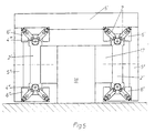
- T-shaped profiled support structure arranged vertically Rail body with two attached at the top and bottom Guide rails are present, and that on the guide carriage two correspondingly arranged upper ones on both sides and lower bearing cheeks, each with two adjustable bearings Recirculating ball bodies are present.
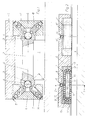
- the linear guide shown in Figures 1 and 2 has a rail body fixedly arranged on a support base 1 2, on both sides in corresponding longitudinal recesses 3 each a guide rail 4 is attached so that it with almost half of its circumference from the rail body 2 protrudes.
- the guide rails 4 have a circular profile and are preferably made of steel, while the rail body 2 can consist of aluminum.
- it has two on both sides below bearing cheeks 6 fastened by him, in each of which two at certain Circumferential points of the associated guide rail 4 rest Recirculating ball bodies 7 are present.
- the bearing cheeks 6 appropriately have the shown, to the guide rails 4 open U-profile. In their inner corners are miter cut lines Receiving slots 8 for each one of them Recirculating ball body 7 available.
- Fig.2 shows, there are 6 in each bearing cheek two recirculating ball bodies 7, 7 'and receiving slots containing them 8 or 8 'arranged coaxially one behind the other, so that each bearing cheek 6 a total of four such ball barrel 7th or 7 'contains. This contributes to the tilt-free management of the Carriage 5, especially with larger length dimensions, at. For shorter carriages 5 can in principle One ball body 7 in the longitudinal direction is already sufficient be.
- Each recirculating ball body 7 consists, as in Fig.2 shows, advantageously from an inside open and closed outside, straight track 9 or 9 'for the recirculating ball series 10 containing metallic middle part 11 and two the latter terminating at both ends, each with a ball deflection track 12 containing plastic end parts 13.
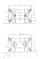
- FIG. 4 shows how an approximately horizontally oriented position of the carriage 5, which is obtained in this case, is obtained with a correspondingly inclined base or rail body 2 by correspondingly different adjustment of the diagonally opposite spherical bodies 7 ′′ ′′ or 7 IV is inclined at a corresponding angle ⁇ to the rail body 2 and to the guide rails 4 thereof. It is understood that in this case the adjustment direction intersection points 16 of the two recirculating ball bodies 7 ''', 7 IV of a bearing cheek 6 cannot coincide with the central longitudinal axis 17 of the guide rail 4, but can differ accordingly.
Landscapes
- Engineering & Computer Science (AREA)
- General Engineering & Computer Science (AREA)
- Mechanical Engineering (AREA)
- Bearings For Parts Moving Linearly (AREA)
- Crystals, And After-Treatments Of Crystals (AREA)
- Magnetic Heads (AREA)
- Valve-Gear Or Valve Arrangements (AREA)
Description
- Fig.1
- eine erste Ausführungsform in der Stirnansicht und im teilweisen Schnitt nach der Linie I-I der
- Fig.2,
- die einen Schnitt durch eine Lagerwange mit Kugelumlaufkörpern entsprechend der Linie II-II der Fig. 1 wiedergibt,
- Fig.3
- eine der Fig.1 entsprechende Ausführungsform, jedoch mit im Durchmesser wesentlich kleineren Führungsschienen,
- Fig.4
- die Stirnansicht der Linearführung bei zwischen Führungsschlitten und Führungsschienen bestehender Schräglage und
- Fig. 5
- eine Linearführung mit insgesamt vier Führungsschienen und der dazugehörigen Anzahl von einzeln verstellbar gelagerten Kugelumlaufkörpern.
Claims (8)
- Linearführung mit zwei beiderseits eines Schienenkörpers (2) vorspringend angeordneten, achsparallel zueinander verlaufenden Führungsschienen (4) und einem darauf längsverschiebbar geführten Schlitten (5), der sich dabei über je zwei in seitlichen, die Führungsschienen (4) umgreifenden Lagerwangen (6) des Schlittens (5) gelegene Linear-Kugellager an zwei verschiedenen Umfangsstellen jeder Führungsschiene (4) abstützt, wobei ein Umlaufkörper (7) jedes Linear-Kugellagers einzeln in den Lagerwangen (6) des Schlittens (5) mit einer Stellschraube (14) radial in Richtung auf die Führungsschiene (4) verstellbar gelagert ist, wobei die Stellschrauben (14) radial in Richtung auf die Führungsschiene (4) eingedreht sind, die Führungsschiene ein kreisrundes Profil besitzt, und die Stellschrauben (14) der Umlaufkörper (7) zum weiten Eindrehen bei einem Anpassen an unterschiedliche Führungsschienendurchmesser mit Kugellagerspiel übersteigenden Durchmesseränderungen ausgebildet sind.
- Linearführung nach Anspruch 1, dadurch gekennzeichnet, daß die beiden jeweils in einer Lagerwange (6) des Führungsschlittens (5) gelegenen Linear-Kugellager rechtwinklig zueinander und unter einem Neigungswinkel von im wesentlichen 45° zu der durch die beiden Führungsschienen verlaufenden Mittelebene (4') verstellbar sind.
- Linearführung nach Anspruch 2, dadurch gekennzeichnet, daß jedes Linear-Kugellager aus einem eine Kugelumlaufreihe (10) längsmittig enthaltenden, im wesentlichen quaderförmigen Kugelumlaufkörper (7) besteht, der in einem zur zugehörigen Führungsschiene (4) hin offenen Aufnahmeschlitz (8) der Lagerwange (6) ringsum gleitverschieblich geführt ist.
- Linearführung nach Anspruch 3, dadurch gekennzeichnet, daß die zu beiden Seiten unterhalb des Führungsschlittens (5) angeordneten Lagerwangen (6) ein zur zugehörigen Führungsschiene (4) hin offenes U-Profil besitzen und die beiden Kugelumlaufkörper (7) und die sie enthaltenden Aufnahmeschlitze (8) in den inneren Ecken des Lagerwangenprofils gehrungsschnittartig liegend angeordnet sind.
- Linearführung nach Anspruch 3, dadurch gekennzeichnet, daß die Kugelumlaufkörper (7) aus einem eine innen offene und außen geschlossene, geradlinige Kugellaufbahn (9 bzw. 9') enthaltenden, metallischen Mittelteil (11) und zwei ihn beidendig abschließenden, je eine Kugelumlenkbahn (12) enthaltenden Endteilen (13) aus insbesondere Kunststoff bestehen.
- Linearführung nach Anspruch 5, dadurch gekennzeichnet, daß die Verstellung der Kugelumlaufkörper (7) über eine oder mehrere Stellschrauben (14) erfolgt, die in in den äußeren Ecken der Lagerwangen (6) des Führungsschlittens (5) gelegenen Gewindebohrungen (15) sitzen und am Rücken (7'') des metallischen Mittelteils (11) der Kugelumlaufkörper (7) angreifen.
- Linearführung nach einem der Ansprüche 1 bis 6, dadurch gekennzeichnet, daß zwei zu beiden Seiten des Kopfes (17) einer T-förmig profilierten Trägerstruktur (18) hochkant angeordnete Schienenkörper (2') mit einer oben und unten daran vorspringend befestigten Führungsschiene (4IV bzw. 4V) vorhanden sind, und daß am Führungsschlitten (5') beidseitig je zwei entsprechend angeordnete, obere und untere Lagerwangen (6' bzw. 6'') mit je zwei in ihnen verstellbar gelagerten Kugelumlaufkörpern (7) vorhanden sind.
- Linearführung nach Anspruch 7, dadurch gekennzeichnet, daß die unteren Lagerwangen (6'') an den unteren Enden von am Führungsschlitten (5') beidseitig angebrachten Seitenwangen (5'') angeordnet sind.
Applications Claiming Priority (3)
| Application Number | Priority Date | Filing Date | Title |
|---|---|---|---|
| DE9209212U DE9209212U1 (de) | 1992-07-09 | 1992-07-09 | Linearführung |
| DE9209212U | 1992-07-09 | ||
| US08/086,590 US5439294A (en) | 1992-07-09 | 1993-07-02 | Linear guide |
Publications (2)
| Publication Number | Publication Date |
|---|---|
| EP0577963A1 EP0577963A1 (de) | 1994-01-12 |
| EP0577963B1 true EP0577963B1 (de) | 1998-09-16 |
Family
ID=25959685
Family Applications (1)
| Application Number | Title | Priority Date | Filing Date |
|---|---|---|---|
| EP93108542A Expired - Lifetime EP0577963B1 (de) | 1992-07-09 | 1993-05-27 | Linearführung |
Country Status (7)
| Country | Link |
|---|---|
| US (1) | US5439294A (de) |
| EP (1) | EP0577963B1 (de) |
| JP (1) | JPH06159360A (de) |
| AT (1) | ATE171250T1 (de) |
| DE (2) | DE9209212U1 (de) |
| DK (1) | DK0577963T3 (de) |
| ES (1) | ES2123016T3 (de) |
Families Citing this family (19)
| Publication number | Priority date | Publication date | Assignee | Title |
|---|---|---|---|---|
| EP0644342A4 (de) * | 1993-03-30 | 1996-10-09 | Thk Co Ltd | Führungseinheit für linearbewegungen und verfahren zu deren zusammenbau. |
| DE29517901U1 (de) * | 1995-11-11 | 1996-01-11 | Foehrenbach Manfred Gmbh | Linearführungseinheit |
| DE29518242U1 (de) * | 1995-11-17 | 1996-01-11 | Isel Automation Hugo Isert | Linearführung |
| US5758975A (en) * | 1997-05-05 | 1998-06-02 | Kuo; Chang-Hsin | Four-way linear ball sliding guide |
| JP2000337471A (ja) * | 1999-05-20 | 2000-12-05 | Sokan Shu | ゼネバ歯車等の駆動側カム |
| BE1015075A3 (nl) * | 2002-08-14 | 2004-09-07 | Werkhuizen Landuyt | Werktafel en bewerkingsmachine, meer bepaald houtbewerkingsmachine omvattende dergelijke werktafel. |
| DE102006014787A1 (de) * | 2006-03-29 | 2007-10-04 | Schaeffler Kg | Linear-Kugellagereinheit |
| DE102007023976A1 (de) * | 2007-05-23 | 2008-11-27 | Schaeffler Kg | Drahtwälzlager |
| DE102008016356A1 (de) * | 2008-03-29 | 2009-10-01 | Schaeffler Kg | Umlaufführung für Wälzkörper und damit ausgerüstete Linear-Führungseinheit |
| JP5224519B2 (ja) * | 2008-09-30 | 2013-07-03 | Thk株式会社 | 運動案内装置 |
| ATE542651T1 (de) * | 2009-09-12 | 2012-02-15 | Scheppach Fabrikation Holzbearbeitungsmaschinen Gmbh | Holzbearbeitungsmaschine und dafuer geeignetes parallelanschlagmodul |
| US8607710B2 (en) | 2010-10-28 | 2013-12-17 | Jack Farr | Cable-tow system having a stationary support cable |
| US10399266B1 (en) * | 2010-11-23 | 2019-09-03 | Allied Dies, Inc. | Die having linear bearing array |
| US10295028B2 (en) | 2016-07-26 | 2019-05-21 | Blockwise Engineering Llc | Linear actuator |
| US11293487B2 (en) * | 2019-12-26 | 2022-04-05 | Erik Jiandong Ma | Slider |
| EP4044206B1 (de) | 2021-02-16 | 2025-04-23 | Hitachi Energy Ltd | Kontakteinheit und kontaktsystem für einen laststufenschalter und laststufenschalter |
| CN114321175B (zh) * | 2021-12-15 | 2024-04-02 | 浙江台鼎科技股份有限公司 | 一种低延迟的叠层式滑块 |
| CN115582707B (zh) * | 2022-11-04 | 2025-07-15 | 沈阳机床股份有限公司 | 加工中心进给轴高速快移的硬宽导轨 |
| KR102665390B1 (ko) * | 2023-11-29 | 2024-05-10 | 주식회사 디에스티엘(Dstl) | 상호 연결이 가능한 lm 가이드 레일 |
Citations (1)
| Publication number | Priority date | Publication date | Assignee | Title |
|---|---|---|---|---|
| US4630872A (en) * | 1984-09-21 | 1986-12-23 | Hiroshi Teramachi | Linear slide bearing |
Family Cites Families (23)
| Publication number | Priority date | Publication date | Assignee | Title |
|---|---|---|---|---|
| US206648A (en) * | 1878-07-30 | Improvement in cross-heads and other slides | ||
| US2595482A (en) * | 1949-04-13 | 1952-05-06 | Vincent E Palumbo | Bearing |
| US2992620A (en) * | 1954-07-12 | 1961-07-18 | Tracerlab Inc | Retractable mount |
| US3436132A (en) * | 1966-05-02 | 1969-04-01 | Teledyne Inc | Slide assembly |
| US3398999A (en) * | 1966-08-15 | 1968-08-27 | Ex Cell O Corp | Linear motion ball bearing assembly |
| US3907385A (en) * | 1974-08-26 | 1975-09-23 | Vermont Marble Co | Arrangement for guiding press rams |
| DE3040711A1 (de) * | 1980-10-29 | 1982-06-03 | Hugo Isert | Fuehrungssystem fuer lineare bewegungen |
| ATE13832T1 (de) * | 1981-11-20 | 1985-07-15 | Isert Elektronik | Fuehrungssystem fuer lineare bewegungen eines werkzeugtraegers. |
| JPS58160623A (ja) * | 1982-03-16 | 1983-09-24 | Hiroshi Teramachi | 無限摺動ベアリングユニツト |
| DE3228762C2 (de) * | 1982-08-02 | 1986-10-16 | Ina Waelzlager Schaeffler Kg, 8522 Herzogenaurach | Wälzlager zur längsbeweglichen Lagerung eines Bauteils mit einer geraden Laufbahn |
| EP0171700B1 (de) * | 1984-08-14 | 1990-04-04 | MAHO Aktiengesellschaft | Einstellbare Wälzkörperumlauf-Geradführung |
| US4573747A (en) * | 1984-10-01 | 1986-03-04 | The Cross Company | Apparatus for aligning a machine tool saddle |
| US4607893A (en) * | 1985-01-11 | 1986-08-26 | Detroit Edge Tool Company | Machine slide bearing assembly |
| DE3509996A1 (de) * | 1985-03-20 | 1986-09-25 | Schaeffler Waelzlager Kg | Vorrichtung zur hoeheneinstellung eines waelzlagers fuer laengsbewegungen |
| DE3533403A1 (de) * | 1985-09-19 | 1987-03-26 | Skf Linearsysteme Gmbh | Waelzlager fuer laengsbewegungen |
| DE8611710U1 (de) * | 1986-04-29 | 1986-06-26 | Isert Elektronik, Hugo Isert, 6419 Eiterfeld | Linearführung |
| DE3629368A1 (de) * | 1986-08-29 | 1988-03-03 | Rixen Wolfgang | Profilstab |
| JPS63190927A (ja) * | 1987-02-03 | 1988-08-08 | Nobuyuki Tsuboi | 無限摺動ベアリング |
| SU1484990A1 (ru) * | 1987-05-04 | 1989-06-07 | Krasnod Otdel S O Proizv Vni | Шариковая направляющая качения |
| JPS6431320A (en) * | 1987-07-28 | 1989-02-01 | Meidensha Electric Mfg Co Ltd | Vacuum interrupter |
| US4944608A (en) * | 1988-03-28 | 1990-07-31 | Nippon Seiko Kabushiki Kaisha | Roller-type linear guide |
| DE3824192C1 (de) * | 1988-07-16 | 1990-02-01 | Werner 6000 Frankfurt De Jacob | |
| US5094549A (en) * | 1990-06-26 | 1992-03-10 | Thomson Industries, Inc. | Linear roller bearing assembly |
-
1992
- 1992-07-09 DE DE9209212U patent/DE9209212U1/de not_active Expired - Lifetime
-
1993
- 1993-05-27 ES ES93108542T patent/ES2123016T3/es not_active Expired - Lifetime
- 1993-05-27 AT AT93108542T patent/ATE171250T1/de not_active IP Right Cessation
- 1993-05-27 DK DK93108542T patent/DK0577963T3/da active
- 1993-05-27 EP EP93108542A patent/EP0577963B1/de not_active Expired - Lifetime
- 1993-05-27 DE DE59308982T patent/DE59308982D1/de not_active Expired - Fee Related
- 1993-07-02 US US08/086,590 patent/US5439294A/en not_active Expired - Lifetime
- 1993-07-08 JP JP5169111A patent/JPH06159360A/ja active Pending
Patent Citations (1)
| Publication number | Priority date | Publication date | Assignee | Title |
|---|---|---|---|---|
| US4630872A (en) * | 1984-09-21 | 1986-12-23 | Hiroshi Teramachi | Linear slide bearing |
Also Published As
| Publication number | Publication date |
|---|---|
| DK0577963T3 (da) | 1999-06-14 |
| ATE171250T1 (de) | 1998-10-15 |
| DE9209212U1 (de) | 1993-11-04 |
| ES2123016T3 (es) | 1999-01-01 |
| DE59308982D1 (de) | 1998-10-22 |
| US5439294A (en) | 1995-08-08 |
| JPH06159360A (ja) | 1994-06-07 |
| EP0577963A1 (de) | 1994-01-12 |
Similar Documents
| Publication | Publication Date | Title |
|---|---|---|
| EP0577963B1 (de) | Linearführung | |
| DE3909292C2 (de) | Längs- und Quer-Tischführungs- und -drehmechanismus | |
| DE69105320T2 (de) | Linearer Führungsmodul zum Verschieben und Handhaben von Teilen und Zubehör. | |
| DE69215273T2 (de) | Linearschlitten | |
| DE102007004057B3 (de) | Zentrierspanner | |
| DE102015114212B4 (de) | Anordnung zum Einspannen eines rotierbaren Werkstücks | |
| DE4041269A1 (de) | Waelzlager fuer linearbewegungen | |
| EP0171700B1 (de) | Einstellbare Wälzkörperumlauf-Geradführung | |
| DE4431286C2 (de) | Linearführung | |
| DE2550743C2 (de) | Durch eine Gewindespindel gesteuerte Positioniervorrichtung | |
| DE3125188C2 (de) | ||
| DE3508604C2 (de) | ||
| DE19619449A1 (de) | Linearführung | |
| DE4310501C1 (de) | Vorrichtung zum steuerbaren Befetten von Werkstücken in Band- oder Platinenform | |
| EP0563699A1 (de) | Plattenzylinder mit einer verstellbaren Spannschiene | |
| EP1113954B1 (de) | Abstützung für einen wagenkasten an einem fahrgestell | |
| EP0139781B1 (de) | Handhabungsgerät | |
| DE102012012530A1 (de) | Linearführung aus wenigstens zwei Profilen | |
| WO1988004972A1 (fr) | Dispositif permettant le deplacement rectiligne de pieces ou d'objets | |
| DE10145321A1 (de) | Lageranordnung für Zylinder, Walzen oder Trommeln | |
| DE19833113A1 (de) | Lagerung für einen Zylinder in einer Druckmaschine | |
| DE9304899U1 (de) | Vorrichtung zum Befetten von Werkstücken in Band- oder Platinenform | |
| DE4022574A1 (de) | Fuehrungssystem fuer werkzeugmaschinen, industrieroboter oder dergleichen | |
| DE10125381A1 (de) | Lagerblock mit Stange | |
| EP1612436A1 (de) | Profilschienenführung |
Legal Events
| Date | Code | Title | Description |
|---|---|---|---|
| PUAI | Public reference made under article 153(3) epc to a published international application that has entered the european phase |
Free format text: ORIGINAL CODE: 0009012 |
|
| AK | Designated contracting states |
Kind code of ref document: A1 Designated state(s): AT BE CH DE DK ES FR GB GR IT LI NL SE |
|
| 17P | Request for examination filed |
Effective date: 19940319 |
|
| 17Q | First examination report despatched |
Effective date: 19950516 |
|
| GRAG | Despatch of communication of intention to grant |
Free format text: ORIGINAL CODE: EPIDOS AGRA |
|
| GRAG | Despatch of communication of intention to grant |
Free format text: ORIGINAL CODE: EPIDOS AGRA |
|
| GRAH | Despatch of communication of intention to grant a patent |
Free format text: ORIGINAL CODE: EPIDOS IGRA |
|
| GRAH | Despatch of communication of intention to grant a patent |
Free format text: ORIGINAL CODE: EPIDOS IGRA |
|
| GRAA | (expected) grant |
Free format text: ORIGINAL CODE: 0009210 |
|
| AK | Designated contracting states |
Kind code of ref document: B1 Designated state(s): AT BE CH DE DK ES FR GB GR IT LI NL SE |
|
| REF | Corresponds to: |
Ref document number: 171250 Country of ref document: AT Date of ref document: 19981015 Kind code of ref document: T |
|
| REG | Reference to a national code |
Ref country code: CH Ref legal event code: EP |
|
| REF | Corresponds to: |
Ref document number: 59308982 Country of ref document: DE Date of ref document: 19981022 |
|
| REG | Reference to a national code |
Ref country code: CH Ref legal event code: NV Representative=s name: E. BLUM & CO. PATENTANWAELTE |
|
| GBT | Gb: translation of ep patent filed (gb section 77(6)(a)/1977) |
Effective date: 19981207 |
|
| ET | Fr: translation filed | ||
| REG | Reference to a national code |
Ref country code: ES Ref legal event code: FG2A Ref document number: 2123016 Country of ref document: ES Kind code of ref document: T3 |
|
| REG | Reference to a national code |
Ref country code: DK Ref legal event code: T3 |
|
| PLBE | No opposition filed within time limit |
Free format text: ORIGINAL CODE: 0009261 |
|
| 26N | No opposition filed | ||
| PGFP | Annual fee paid to national office [announced via postgrant information from national office to epo] |
Ref country code: GB Payment date: 20010412 Year of fee payment: 9 |
|
| PGFP | Annual fee paid to national office [announced via postgrant information from national office to epo] |
Ref country code: CH Payment date: 20010418 Year of fee payment: 9 |
|
| PGFP | Annual fee paid to national office [announced via postgrant information from national office to epo] |
Ref country code: GR Payment date: 20010427 Year of fee payment: 9 Ref country code: AT Payment date: 20010427 Year of fee payment: 9 |
|
| PGFP | Annual fee paid to national office [announced via postgrant information from national office to epo] |
Ref country code: SE Payment date: 20010503 Year of fee payment: 9 Ref country code: DK Payment date: 20010503 Year of fee payment: 9 |
|
| PGFP | Annual fee paid to national office [announced via postgrant information from national office to epo] |
Ref country code: FR Payment date: 20010507 Year of fee payment: 9 |
|
| PGFP | Annual fee paid to national office [announced via postgrant information from national office to epo] |
Ref country code: NL Payment date: 20010509 Year of fee payment: 9 |
|
| PGFP | Annual fee paid to national office [announced via postgrant information from national office to epo] |
Ref country code: ES Payment date: 20010514 Year of fee payment: 9 Ref country code: BE Payment date: 20010514 Year of fee payment: 9 |
|
| REG | Reference to a national code |
Ref country code: GB Ref legal event code: IF02 |
|
| PG25 | Lapsed in a contracting state [announced via postgrant information from national office to epo] |
Ref country code: GB Free format text: LAPSE BECAUSE OF NON-PAYMENT OF DUE FEES Effective date: 20020527 Ref country code: AT Free format text: LAPSE BECAUSE OF NON-PAYMENT OF DUE FEES Effective date: 20020527 |
|
| PG25 | Lapsed in a contracting state [announced via postgrant information from national office to epo] |
Ref country code: SE Free format text: LAPSE BECAUSE OF NON-PAYMENT OF DUE FEES Effective date: 20020528 Ref country code: ES Free format text: LAPSE BECAUSE OF NON-PAYMENT OF DUE FEES Effective date: 20020528 |
|
| PG25 | Lapsed in a contracting state [announced via postgrant information from national office to epo] |
Ref country code: LI Free format text: LAPSE BECAUSE OF NON-PAYMENT OF DUE FEES Effective date: 20020531 Ref country code: DK Free format text: LAPSE BECAUSE OF NON-PAYMENT OF DUE FEES Effective date: 20020531 Ref country code: CH Free format text: LAPSE BECAUSE OF NON-PAYMENT OF DUE FEES Effective date: 20020531 Ref country code: BE Free format text: LAPSE BECAUSE OF NON-PAYMENT OF DUE FEES Effective date: 20020531 |
|
| PG25 | Lapsed in a contracting state [announced via postgrant information from national office to epo] |
Ref country code: NL Free format text: LAPSE BECAUSE OF NON-PAYMENT OF DUE FEES Effective date: 20021201 |
|
| PG25 | Lapsed in a contracting state [announced via postgrant information from national office to epo] |
Ref country code: GR Free format text: LAPSE BECAUSE OF NON-PAYMENT OF DUE FEES Effective date: 20021206 |
|
| REG | Reference to a national code |
Ref country code: DK Ref legal event code: EBP |
|
| EUG | Se: european patent has lapsed | ||
| GBPC | Gb: european patent ceased through non-payment of renewal fee |
Effective date: 20020527 |
|
| REG | Reference to a national code |
Ref country code: CH Ref legal event code: PL |
|
| PG25 | Lapsed in a contracting state [announced via postgrant information from national office to epo] |
Ref country code: FR Free format text: LAPSE BECAUSE OF NON-PAYMENT OF DUE FEES Effective date: 20030131 |
|
| NLV4 | Nl: lapsed or anulled due to non-payment of the annual fee |
Effective date: 20021201 |
|
| REG | Reference to a national code |
Ref country code: FR Ref legal event code: ST |
|
| REG | Reference to a national code |
Ref country code: ES Ref legal event code: FD2A Effective date: 20030611 |
|
| PG25 | Lapsed in a contracting state [announced via postgrant information from national office to epo] |
Ref country code: IT Free format text: LAPSE BECAUSE OF NON-PAYMENT OF DUE FEES;WARNING: LAPSES OF ITALIAN PATENTS WITH EFFECTIVE DATE BEFORE 2007 MAY HAVE OCCURRED AT ANY TIME BEFORE 2007. THE CORRECT EFFECTIVE DATE MAY BE DIFFERENT FROM THE ONE RECORDED. Effective date: 20050527 |
|
| PGFP | Annual fee paid to national office [announced via postgrant information from national office to epo] |
Ref country code: DE Payment date: 20090729 Year of fee payment: 17 |
|
| PG25 | Lapsed in a contracting state [announced via postgrant information from national office to epo] |
Ref country code: DE Free format text: LAPSE BECAUSE OF NON-PAYMENT OF DUE FEES Effective date: 20101201 |