EP0578126A2 - Réservoir d'eau chaude à température non-uniforme avec échangeur de chaleur à contre-courant sans source d'énergie externe - Google Patents
Réservoir d'eau chaude à température non-uniforme avec échangeur de chaleur à contre-courant sans source d'énergie externe Download PDFInfo
- Publication number
- EP0578126A2 EP0578126A2 EP93110482A EP93110482A EP0578126A2 EP 0578126 A2 EP0578126 A2 EP 0578126A2 EP 93110482 A EP93110482 A EP 93110482A EP 93110482 A EP93110482 A EP 93110482A EP 0578126 A2 EP0578126 A2 EP 0578126A2
- Authority
- EP
- European Patent Office
- Prior art keywords
- water
- storage tank
- heat exchanger
- hot water
- stratified
- Prior art date
- Legal status (The legal status is an assumption and is not a legal conclusion. Google has not performed a legal analysis and makes no representation as to the accuracy of the status listed.)
- Granted
Links
Images

Classifications
-
- F—MECHANICAL ENGINEERING; LIGHTING; HEATING; WEAPONS; BLASTING
- F28—HEAT EXCHANGE IN GENERAL
- F28D—HEAT-EXCHANGE APPARATUS, NOT PROVIDED FOR IN ANOTHER SUBCLASS, IN WHICH THE HEAT-EXCHANGE MEDIA DO NOT COME INTO DIRECT CONTACT
- F28D20/00—Heat storage plants or apparatus in general; Regenerative heat-exchange apparatus not covered by groups F28D17/00 or F28D19/00
- F28D20/0034—Heat storage plants or apparatus in general; Regenerative heat-exchange apparatus not covered by groups F28D17/00 or F28D19/00 using liquid heat storage material
- F28D20/0039—Heat storage plants or apparatus in general; Regenerative heat-exchange apparatus not covered by groups F28D17/00 or F28D19/00 using liquid heat storage material with stratification of the heat storage material
-
- F—MECHANICAL ENGINEERING; LIGHTING; HEATING; WEAPONS; BLASTING
- F24—HEATING; RANGES; VENTILATING
- F24H—FLUID HEATERS, e.g. WATER OR AIR HEATERS, HAVING HEAT-GENERATING MEANS, e.g. HEAT PUMPS, IN GENERAL
- F24H1/00—Water heaters, e.g. boilers, continuous-flow heaters or water-storage heaters
- F24H1/18—Water-storage heaters
- F24H1/20—Water-storage heaters with immersed heating elements, e.g. electric elements or furnace tubes
- F24H1/208—Water-storage heaters with immersed heating elements, e.g. electric elements or furnace tubes with tubes filled with heat transfer fluid
-
- F—MECHANICAL ENGINEERING; LIGHTING; HEATING; WEAPONS; BLASTING
- F28—HEAT EXCHANGE IN GENERAL
- F28D—HEAT-EXCHANGE APPARATUS, NOT PROVIDED FOR IN ANOTHER SUBCLASS, IN WHICH THE HEAT-EXCHANGE MEDIA DO NOT COME INTO DIRECT CONTACT
- F28D20/00—Heat storage plants or apparatus in general; Regenerative heat-exchange apparatus not covered by groups F28D17/00 or F28D19/00
- F28D2020/0065—Details, e.g. particular heat storage tanks, auxiliary members within tanks
- F28D2020/0069—Distributing arrangements; Fluid deflecting means
-
- F—MECHANICAL ENGINEERING; LIGHTING; HEATING; WEAPONS; BLASTING
- F28—HEAT EXCHANGE IN GENERAL
- F28D—HEAT-EXCHANGE APPARATUS, NOT PROVIDED FOR IN ANOTHER SUBCLASS, IN WHICH THE HEAT-EXCHANGE MEDIA DO NOT COME INTO DIRECT CONTACT
- F28D20/00—Heat storage plants or apparatus in general; Regenerative heat-exchange apparatus not covered by groups F28D17/00 or F28D19/00
- F28D2020/0065—Details, e.g. particular heat storage tanks, auxiliary members within tanks
- F28D2020/0078—Heat exchanger arrangements
-
- Y—GENERAL TAGGING OF NEW TECHNOLOGICAL DEVELOPMENTS; GENERAL TAGGING OF CROSS-SECTIONAL TECHNOLOGIES SPANNING OVER SEVERAL SECTIONS OF THE IPC; TECHNICAL SUBJECTS COVERED BY FORMER USPC CROSS-REFERENCE ART COLLECTIONS [XRACs] AND DIGESTS
- Y02—TECHNOLOGIES OR APPLICATIONS FOR MITIGATION OR ADAPTATION AGAINST CLIMATE CHANGE
- Y02B—CLIMATE CHANGE MITIGATION TECHNOLOGIES RELATED TO BUILDINGS, e.g. HOUSING, HOUSE APPLIANCES OR RELATED END-USER APPLICATIONS
- Y02B10/00—Integration of renewable energy sources in buildings
- Y02B10/50—Hydropower in dwellings
-
- Y—GENERAL TAGGING OF NEW TECHNOLOGICAL DEVELOPMENTS; GENERAL TAGGING OF CROSS-SECTIONAL TECHNOLOGIES SPANNING OVER SEVERAL SECTIONS OF THE IPC; TECHNICAL SUBJECTS COVERED BY FORMER USPC CROSS-REFERENCE ART COLLECTIONS [XRACs] AND DIGESTS
- Y02—TECHNOLOGIES OR APPLICATIONS FOR MITIGATION OR ADAPTATION AGAINST CLIMATE CHANGE
- Y02E—REDUCTION OF GREENHOUSE GAS [GHG] EMISSIONS, RELATED TO ENERGY GENERATION, TRANSMISSION OR DISTRIBUTION
- Y02E60/00—Enabling technologies; Technologies with a potential or indirect contribution to GHG emissions mitigation
- Y02E60/14—Thermal energy storage
Definitions
- Solar collectors are used in most cases for the production of hot industrial water, since here a significant part of the annual energy required for the production of hot water can be covered by solar energy.
- Hot water storage tanks are mostly used to temporarily store the thermal energy collected.
- the present invention relates to a hot water tank that enables stratified loading and unloading without the disadvantages mentioned above.
- the memory according to the invention is preferably operated without pressure, so that e.g. an inexpensive plastic construction is made possible.
- the storage walls must be constructed from a poorly heat-conducting material in order to avoid rapid temperature compensation between the warmer and the colder water layers. This is useful for loading the storage tank with a solar system, e.g. common drainage system in the Netherlands ("drainback system”) (no antifreeze required, good heat transfer in the collector, no solar heat exchanger in the storage tank).
- the water which is preferably circulated by a thermostatically controlled pump, is drawn off from the lower part of the store and, after heating to the desired final temperature, is conducted into the upper part of the store, the laminar layering possibly being ensured by a calming plate.
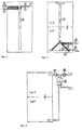
- the hot water is heated in a heat exchanger in which, in countercurrent to the hot water, the warm water from the upper region of the storage tank is cooled, and is conducted into the lower area of the storage without effort from external energy.
- the heat exchanger is located in the upper area of the storage tank. Cold process water is heated as it flows through the heat exchanger. At the same time, the hot storage water in the vicinity of the heat exchanger is cooled. This cooled storage water now has a greater density, so that a counterflow to the process water through the heat exchanger is set down. An outflow channel is connected to the heat exchanger, which prevents mixing of cooled and hot storage water.
- the heat exchanger is constructed according to claim 3 from a finned tube (1) (preferably copper).
- the finned tube is spirally wound and arranged between two separating surfaces (2), which means that the storage water must flow through the spaces between the fins.
- a finned tube (1) preferably copper
- the finned tube is spirally wound and arranged between two separating surfaces (2), which means that the storage water must flow through the spaces between the fins.
- Guide structures for example an inserted rubber band (see FIG. 2, (3)), are attached between the turns of the finned tube, as a result of which the gap between the fins and separating surfaces is sealed.
- Another possibility according to the invention is according to claims 9 and 10 the use of finned tubes with angular fins or their approximation by bending the edges of round fins.
- the separating surfaces are made of a poorly heat-conducting material, preferably plastic, in order to avoid direct thermal contact between cooler and warmer areas of the heat exchanger and the surrounding hot storage water.
- the cold water connection (4) isolated inside the storage tank is located at the lower end of the finned tube spiral, the hot water outlet (5) at the higher end.
- Storage water that sinks through the heat exchanger from above flows in a countercurrent to the rising process water through the heat exchanger.
- the channel formed by the separating surfaces (2) opens into an outflow channel (6) which is made of a poorly heat-conducting material, preferably a plastic tube.
- the discharge pipe extends up to a few centimeters above the storage floor, where the cooled storage water is layered.
- the cross-section of the outflow channel must not be too large, since between each withdrawal of hot water due to a pressure equalization between the outflow pipe and the rest of the tank, the pipe is filled with hot water according to the layer height in the storage tank. This warm water must be displaced downwards into the cooler storage part each time hot water is removed, which on the one hand hinders the formation of the thermosiphon circuit and on the other hand the stratification in the hot water tank is reduced. If the cross-section of the outflow pipe becomes too small, however, the flow resistance becomes too large, which in turn impairs the thermosiphon circuit.
- the entire heat exchanger is arranged as high as possible in the storage tank so that a thermosiphon flow can still develop even with a largely discharged storage tank with a narrow hot water layer.
- thermodynamically best countercurrent heat exchange is achieved when the pressure loss in the entire heat exchanger is so great that the mean one that arises Storage water flow roughly corresponds to the typical process water flow.
- the storage water could be cooled by approx. 17 K when the storage tank was full and 28 K when the storage tank was almost empty.
- the hot water temperature was initially around 57 ° C and dropped to around 45 ° C towards the end of the discharge.
- FIG. 6 shows a second principle according to the invention, which enables the circulation of storage water free of external energy by means of a counterflow heat exchanger:
- the process water drives a small turbine (10) or a water motor, whereby part of the line pressure is reduced.
- Smallest pump (11) driven, which sends hot storage water from the upper storage area through a counterflow heat exchanger (12), in which the process water is heated and the storage water is cooled.
- the cooled storage water is reintroduced into the lower area of the storage so that it does not mix with warmer layers (eg below a calming plate).
- the direct coupling of the drive unit and the pump and a corresponding dimensioning ensure that the mass flow of the domestic water to be heated and that of the storage water to be cooled are approximately the same for each withdrawal quantity, which is a prerequisite for a thermodynamically optimal countercurrent heat exchange.
- a water pump that operates according to the positive displacement principle with low friction e.g. a gear pump
- a gear pump can be operated in reverse.
- the water motor or turbine and pump are connected to one another by a magnetic coupling.
Landscapes
- Engineering & Computer Science (AREA)
- Physics & Mathematics (AREA)
- Thermal Sciences (AREA)
- Mechanical Engineering (AREA)
- General Engineering & Computer Science (AREA)
- Chemical & Material Sciences (AREA)
- Combustion & Propulsion (AREA)
- Heat-Pump Type And Storage Water Heaters (AREA)
- Heat-Exchange Devices With Radiators And Conduit Assemblies (AREA)
- Central Heating Systems (AREA)
Applications Claiming Priority (2)
| Application Number | Priority Date | Filing Date | Title |
|---|---|---|---|
| DE4221668 | 1992-07-02 | ||
| DE4221668A DE4221668C2 (de) | 1992-07-02 | 1992-07-02 | Warmwasser-Schichtenspeicher mit Gegenstromwärmetauscher |
Publications (3)
| Publication Number | Publication Date |
|---|---|
| EP0578126A2 true EP0578126A2 (fr) | 1994-01-12 |
| EP0578126A3 EP0578126A3 (fr) | 1994-12-28 |
| EP0578126B1 EP0578126B1 (fr) | 1998-05-13 |
Family
ID=6462286
Family Applications (1)
| Application Number | Title | Priority Date | Filing Date |
|---|---|---|---|
| EP93110482A Expired - Lifetime EP0578126B1 (fr) | 1992-07-02 | 1993-07-01 | Réservoir d'eau chaude à température non-uniforme avec échangeur de chaleur à contre-courant sans source d'énergie externe |
Country Status (3)
| Country | Link |
|---|---|
| EP (1) | EP0578126B1 (fr) |
| AT (1) | ATE166148T1 (fr) |
| DE (2) | DE4221668C2 (fr) |
Cited By (8)
| Publication number | Priority date | Publication date | Assignee | Title |
|---|---|---|---|---|
| DE4443715A1 (de) * | 1994-12-09 | 1996-06-13 | Solvis Solarsysteme Gmbh | Warmwasserbereiter |
| DE19710803C2 (de) * | 1997-03-17 | 1999-09-02 | Wagner & Co Solartechnik Gmbh | Warmwasser-Speichersystem |
| AT412740B (de) * | 2003-03-25 | 2005-06-27 | Seebacher Theodor | Vorrichtung zum erwärmen einer flüssigkeit, z.b. brauchwasser |
| EP1772676A3 (fr) * | 2005-10-10 | 2009-02-25 | Hebert Ganglberger | Installation d'échange de chaleur |
| EP2407663A2 (fr) | 2010-07-13 | 2012-01-18 | SOLARFOCUS Holding GmbH | Appareil de commande d'une turbine hydraulique |
| DE10232700B4 (de) * | 2002-07-15 | 2012-06-14 | Frank Meyer zur Heide | Aqua-Re-Energie-Trichter |
| EP2031312A3 (fr) * | 2007-08-31 | 2013-09-11 | Johann Kalkgruber | Dispositif de chauffage d'eau potable lors du passage |
| EP2489945A3 (fr) * | 2011-02-18 | 2014-01-22 | Robert Laabmayr | Accumulateur thermique |
Families Citing this family (11)
| Publication number | Priority date | Publication date | Assignee | Title |
|---|---|---|---|---|
| DE19516837C2 (de) * | 1995-05-08 | 1998-07-16 | Winfried Hesse | Behälter mit einer Flüssigkeit zur Wärme- oder Kältespeicherung |
| DE19703724C2 (de) * | 1997-01-22 | 1999-06-10 | Zenit Energietechnik Gmbh | Druckloser Warmwasser-Speicher aus Kunststoff für die Solar-Wärmetechnik |
| DE19703722C2 (de) * | 1997-01-22 | 1999-06-10 | Zenit Energietechnik Gmbh | Druckloser Warmwasser - Speicher aus Kunststoff für die Solar - Wärmetechnik |
| DE10121842C2 (de) * | 2001-05-05 | 2003-10-02 | Consolar Energiespeicher Und R | Entladewärmetauscher für Wärmespeicher |
| DE102004031789A1 (de) * | 2004-07-01 | 2005-11-03 | Robert Bosch Gmbh | Heizeinrichtung, insbesondere Wasserheizeinrichtung |
| DE102004048884B4 (de) * | 2004-10-06 | 2013-11-14 | Frank Triesch | Wärmeübertrager |
| DE102010004984A1 (de) * | 2010-01-19 | 2011-07-21 | IVT Installations- und Verbindungstechnik GmbH & Co. KG, 91126 | Wärmespeicher |
| DE102010046154A1 (de) * | 2010-09-21 | 2012-03-22 | Ivt Installations- Und Verbindungstechnik Gmbh & Co. Kg | Wärmespeicher |
| DE102012001085A1 (de) | 2012-01-20 | 2013-07-25 | Efficient Home Energy, S.L. | Vorrichtung zur Erwärmung von Brauchwasser |
| DE202016005844U1 (de) | 2016-09-24 | 2016-10-13 | Consolar Solare Energiesysteme Gmbh | Wärmespeicher mit Warmwasser-Wärmetauscher |
| CN107522311A (zh) * | 2017-10-19 | 2017-12-29 | 王云龙 | 一种净水机 |
Family Cites Families (10)
| Publication number | Priority date | Publication date | Assignee | Title |
|---|---|---|---|---|
| CH180906A (de) * | 1935-01-09 | 1935-11-30 | Ctc Ab | Warmwasserversorgungsanlage mit mittelbarer Erwärmung des Abzapfwassers in einem Rohrsystem. |
| US4174009A (en) * | 1974-09-30 | 1979-11-13 | Ingeborg Laing | Long-period thermal storage accumulators |
| DE3003688C2 (de) * | 1980-02-01 | 1982-10-14 | Messerschmitt-Bölkow-Blohm GmbH, 8000 München | Wärmespeicheranlage mit einem flüssigen Wärmeträger und einem Speichertank |
| SU979711A2 (ru) * | 1980-05-26 | 1982-12-07 | Предприятие П/Я Г-4147 | Турбонасосный агрегат |
| DE3044079C2 (de) * | 1980-11-24 | 1986-11-20 | Schmidt Reuter Ingenieurgesellschaft mbH & Co KG, 5000 Köln | Warmwasserspeicher |
| FR2600146B1 (fr) * | 1986-06-13 | 1988-09-09 | Olivet Jacques | Installation de chauffage |
| DE8703576U1 (de) * | 1987-03-10 | 1987-04-23 | DMS - Kalt- und Warmwassertechnik Mühlena - Schöps - Tittel oHG, 2000 Oststeinbek | Speicher-Brauchwasser-Erwärmer |
| DD263113A1 (de) * | 1987-07-20 | 1988-12-21 | Schwerin Energiekombinat | Anordnung zur wirbelfreien einleitung von speichermedien in schichtwaermespeicherbehaelter |
| DE9017908U1 (de) * | 1990-09-15 | 1992-11-05 | Herrmann GmbH + Co. KG, 5840 Schwerte | Warmwasserschichtenspeicher |
| DE4119542C1 (fr) * | 1991-06-13 | 1993-01-14 | Thermo-Solar Energietechnik Gmbh, 8400 Regensburg, De |
-
1992
- 1992-07-02 DE DE4221668A patent/DE4221668C2/de not_active Expired - Fee Related
-
1993
- 1993-07-01 AT AT93110482T patent/ATE166148T1/de not_active IP Right Cessation
- 1993-07-01 EP EP93110482A patent/EP0578126B1/fr not_active Expired - Lifetime
- 1993-07-01 DE DE59308528T patent/DE59308528D1/de not_active Expired - Lifetime
Cited By (9)
| Publication number | Priority date | Publication date | Assignee | Title |
|---|---|---|---|---|
| DE4443715A1 (de) * | 1994-12-09 | 1996-06-13 | Solvis Solarsysteme Gmbh | Warmwasserbereiter |
| WO1996018072A1 (fr) | 1994-12-09 | 1996-06-13 | Solvis Solarsysteme Gmbh | Chauffe-eau |
| DE19710803C2 (de) * | 1997-03-17 | 1999-09-02 | Wagner & Co Solartechnik Gmbh | Warmwasser-Speichersystem |
| DE10232700B4 (de) * | 2002-07-15 | 2012-06-14 | Frank Meyer zur Heide | Aqua-Re-Energie-Trichter |
| AT412740B (de) * | 2003-03-25 | 2005-06-27 | Seebacher Theodor | Vorrichtung zum erwärmen einer flüssigkeit, z.b. brauchwasser |
| EP1772676A3 (fr) * | 2005-10-10 | 2009-02-25 | Hebert Ganglberger | Installation d'échange de chaleur |
| EP2031312A3 (fr) * | 2007-08-31 | 2013-09-11 | Johann Kalkgruber | Dispositif de chauffage d'eau potable lors du passage |
| EP2407663A2 (fr) | 2010-07-13 | 2012-01-18 | SOLARFOCUS Holding GmbH | Appareil de commande d'une turbine hydraulique |
| EP2489945A3 (fr) * | 2011-02-18 | 2014-01-22 | Robert Laabmayr | Accumulateur thermique |
Also Published As
| Publication number | Publication date |
|---|---|
| DE4221668C2 (de) | 1998-07-16 |
| DE4221668A1 (de) | 1994-01-13 |
| EP0578126A3 (fr) | 1994-12-28 |
| ATE166148T1 (de) | 1998-05-15 |
| EP0578126B1 (fr) | 1998-05-13 |
| DE59308528D1 (de) | 1998-06-18 |
Similar Documents
| Publication | Publication Date | Title |
|---|---|---|
| EP0578126A2 (fr) | Réservoir d'eau chaude à température non-uniforme avec échangeur de chaleur à contre-courant sans source d'énergie externe | |
| EP0006211B1 (fr) | Dispositif pour la préparation d'eau chaude par l'énergie solaire | |
| DE4438970A1 (de) | Modularer Wärmespeicher | |
| DD148252A5 (de) | Thermoisolierter waermespeicher | |
| EP0561032B1 (fr) | Accumulateur de chaleur comme accumulateur tampon pour un chauffage de locaux | |
| EP2543949A2 (fr) | Accumulateur thermique pourvu d'un récipient en partie rempli de liquide | |
| WO2004046632A1 (fr) | Echangeur thermique a accumulation, procedes de fonctionnement et utilisation associes | |
| DE102011056864A1 (de) | Wärmeversorgungssystem und Wärmeversorgungsverfahren | |
| WO2002012814A1 (fr) | Accumulateur de chaleur latente | |
| DE10108150A1 (de) | Latentwärmespeicher | |
| DE102007059099A1 (de) | Stehender Schichtenwärmespeicher | |
| EP3473943B1 (fr) | Procédé et dispositif de climatisation de pièces à l'aide des éléments en béton à activité thermique | |
| EP3296677A1 (fr) | Procédé de stockage de chaleur | |
| DE102009005637A1 (de) | Energiespeicher | |
| DE19707158A1 (de) | Kälteanlage | |
| EP1010961B1 (fr) | Stockage de chaleur | |
| DE29705642U1 (de) | Druckloser Wärmespeicher | |
| WO2015150010A1 (fr) | Système accumulateur de pression et procédé permettant de faire fonctionner ledit système | |
| EP4521036B1 (fr) | Système de réservoir bivalent multifonction | |
| DE29816006U1 (de) | Haus- oder Raumheizungssystem mit Wärmespeicherung | |
| EP4581319A1 (fr) | Unité de stockage de chaleur et de froid ayant un échangeur de chaleur à contre-courant | |
| DE2431940A1 (de) | Verfahren zum transportieren der waerme von einem waermeren element zu einem kaelteren und waermeleitungssystem zum durchfuehren dieses verfahrens | |
| DE3228956A1 (de) | Vorrichtung zum aufheizen des nutz- und heizwassers | |
| DE4014243A1 (de) | Latentwaermespeicher | |
| DE20317010U1 (de) | Wärmespeicher mit thermosiphonischem Gegenstromwärmetauscher aus Flachrohrwendel |
Legal Events
| Date | Code | Title | Description |
|---|---|---|---|
| PUAI | Public reference made under article 153(3) epc to a published international application that has entered the european phase |
Free format text: ORIGINAL CODE: 0009012 |
|
| AK | Designated contracting states |
Kind code of ref document: A2 Designated state(s): AT BE CH DE DK FR GB LI NL SE |
|
| PUAL | Search report despatched |
Free format text: ORIGINAL CODE: 0009013 |
|
| AK | Designated contracting states |
Kind code of ref document: A3 Designated state(s): AT BE CH DE DK FR GB LI NL SE |
|
| RAP1 | Party data changed (applicant data changed or rights of an application transferred) |
Owner name: LEIBFRIED, ULRICH |
|
| RIN1 | Information on inventor provided before grant (corrected) |
Inventor name: LEIBFRIED, ULRICH |
|
| 17P | Request for examination filed |
Effective date: 19950622 |
|
| 17Q | First examination report despatched |
Effective date: 19960826 |
|
| GRAG | Despatch of communication of intention to grant |
Free format text: ORIGINAL CODE: EPIDOS AGRA |
|
| GRAG | Despatch of communication of intention to grant |
Free format text: ORIGINAL CODE: EPIDOS AGRA |
|
| GRAG | Despatch of communication of intention to grant |
Free format text: ORIGINAL CODE: EPIDOS AGRA |
|
| GRAH | Despatch of communication of intention to grant a patent |
Free format text: ORIGINAL CODE: EPIDOS IGRA |
|
| GRAH | Despatch of communication of intention to grant a patent |
Free format text: ORIGINAL CODE: EPIDOS IGRA |
|
| GRAA | (expected) grant |
Free format text: ORIGINAL CODE: 0009210 |
|
| AK | Designated contracting states |
Kind code of ref document: B1 Designated state(s): AT BE CH DE DK FR GB LI NL SE |
|
| PG25 | Lapsed in a contracting state [announced via postgrant information from national office to epo] |
Ref country code: GB Free format text: LAPSE BECAUSE OF FAILURE TO SUBMIT A TRANSLATION OF THE DESCRIPTION OR TO PAY THE FEE WITHIN THE PRESCRIBED TIME-LIMIT Effective date: 19980513 |
|
| REF | Corresponds to: |
Ref document number: 166148 Country of ref document: AT Date of ref document: 19980515 Kind code of ref document: T |
|
| REG | Reference to a national code |
Ref country code: CH Ref legal event code: EP |
|
| REF | Corresponds to: |
Ref document number: 59308528 Country of ref document: DE Date of ref document: 19980618 |
|
| REG | Reference to a national code |
Ref country code: CH Ref legal event code: NV Representative=s name: HANS RUDOLF GACHNANG PATENTANWALT |
|
| PG25 | Lapsed in a contracting state [announced via postgrant information from national office to epo] |
Ref country code: SE Free format text: LAPSE BECAUSE OF FAILURE TO SUBMIT A TRANSLATION OF THE DESCRIPTION OR TO PAY THE FEE WITHIN THE PRESCRIBED TIME-LIMIT Effective date: 19980813 Ref country code: DK Free format text: LAPSE BECAUSE OF FAILURE TO SUBMIT A TRANSLATION OF THE DESCRIPTION OR TO PAY THE FEE WITHIN THE PRESCRIBED TIME-LIMIT Effective date: 19980813 |
|
| ET | Fr: translation filed | ||
| GBV | Gb: ep patent (uk) treated as always having been void in accordance with gb section 77(7)/1977 [no translation filed] |
Effective date: 19980513 |
|
| PLBE | No opposition filed within time limit |
Free format text: ORIGINAL CODE: 0009261 |
|
| STAA | Information on the status of an ep patent application or granted ep patent |
Free format text: STATUS: NO OPPOSITION FILED WITHIN TIME LIMIT |
|
| 26N | No opposition filed | ||
| PGFP | Annual fee paid to national office [announced via postgrant information from national office to epo] |
Ref country code: NL Payment date: 20000719 Year of fee payment: 8 |
|
| PG25 | Lapsed in a contracting state [announced via postgrant information from national office to epo] |
Ref country code: NL Free format text: LAPSE BECAUSE OF NON-PAYMENT OF DUE FEES Effective date: 20020201 |
|
| NLV4 | Nl: lapsed or anulled due to non-payment of the annual fee |
Effective date: 20020201 |
|
| PGFP | Annual fee paid to national office [announced via postgrant information from national office to epo] |
Ref country code: AT Payment date: 20030716 Year of fee payment: 11 |
|
| PGFP | Annual fee paid to national office [announced via postgrant information from national office to epo] |
Ref country code: CH Payment date: 20030718 Year of fee payment: 11 |
|
| PG25 | Lapsed in a contracting state [announced via postgrant information from national office to epo] |
Ref country code: AT Free format text: LAPSE BECAUSE OF NON-PAYMENT OF DUE FEES Effective date: 20040701 |
|
| PG25 | Lapsed in a contracting state [announced via postgrant information from national office to epo] |
Ref country code: LI Free format text: LAPSE BECAUSE OF NON-PAYMENT OF DUE FEES Effective date: 20040731 Ref country code: CH Free format text: LAPSE BECAUSE OF NON-PAYMENT OF DUE FEES Effective date: 20040731 |
|
| PGFP | Annual fee paid to national office [announced via postgrant information from national office to epo] |
Ref country code: FR Payment date: 20040818 Year of fee payment: 12 Ref country code: BE Payment date: 20040818 Year of fee payment: 12 |
|
| REG | Reference to a national code |
Ref country code: CH Ref legal event code: PL |
|
| PG25 | Lapsed in a contracting state [announced via postgrant information from national office to epo] |
Ref country code: FR Free format text: LAPSE BECAUSE OF NON-PAYMENT OF DUE FEES Effective date: 20050331 |
|
| REG | Reference to a national code |
Ref country code: FR Ref legal event code: ST |
|
| PG25 | Lapsed in a contracting state [announced via postgrant information from national office to epo] |
Ref country code: BE Free format text: LAPSE BECAUSE OF NON-PAYMENT OF DUE FEES Effective date: 20050731 |
|
| REG | Reference to a national code |
Ref country code: FR Ref legal event code: D3 |
|
| REG | Reference to a national code |
Ref country code: FR Ref legal event code: ST Effective date: 20060331 |
|
| BERE | Be: lapsed |
Owner name: *LEIBFRIED ULRICH Effective date: 20050731 |
|
| PGFP | Annual fee paid to national office [announced via postgrant information from national office to epo] |
Ref country code: DE Payment date: 20110731 Year of fee payment: 19 |
|
| PG25 | Lapsed in a contracting state [announced via postgrant information from national office to epo] |
Ref country code: DE Free format text: LAPSE BECAUSE OF NON-PAYMENT OF DUE FEES Effective date: 20130201 |
|
| REG | Reference to a national code |
Ref country code: DE Ref legal event code: R119 Ref document number: 59308528 Country of ref document: DE Effective date: 20130201 |