EP0578146B1 - Procédé et dispositif pour détecter la présence de salissures dans des bouteilles - Google Patents
Procédé et dispositif pour détecter la présence de salissures dans des bouteilles Download PDFInfo
- Publication number
- EP0578146B1 EP0578146B1 EP93110577A EP93110577A EP0578146B1 EP 0578146 B1 EP0578146 B1 EP 0578146B1 EP 93110577 A EP93110577 A EP 93110577A EP 93110577 A EP93110577 A EP 93110577A EP 0578146 B1 EP0578146 B1 EP 0578146B1
- Authority
- EP
- European Patent Office
- Prior art keywords
- test station
- bottles
- bottle
- gas sample
- testing
- Prior art date
- Legal status (The legal status is an assumption and is not a legal conclusion. Google has not performed a legal analysis and makes no representation as to the accuracy of the status listed.)
- Expired - Lifetime
Links
Images


Classifications
-
- G—PHYSICS
- G01—MEASURING; TESTING
- G01N—INVESTIGATING OR ANALYSING MATERIALS BY DETERMINING THEIR CHEMICAL OR PHYSICAL PROPERTIES
- G01N1/00—Sampling; Preparing specimens for investigation
- G01N1/02—Devices for withdrawing samples
- G01N1/22—Devices for withdrawing samples in the gaseous state
- G01N1/26—Devices for withdrawing samples in the gaseous state with provision for intake from several spaces
-
- B—PERFORMING OPERATIONS; TRANSPORTING
- B08—CLEANING
- B08B—CLEANING IN GENERAL; PREVENTION OF FOULING IN GENERAL
- B08B9/00—Cleaning hollow articles by methods or apparatus specially adapted thereto
- B08B9/08—Cleaning containers, e.g. tanks
- B08B9/46—Inspecting cleaned containers for cleanliness
-
- G—PHYSICS
- G01—MEASURING; TESTING
- G01N—INVESTIGATING OR ANALYSING MATERIALS BY DETERMINING THEIR CHEMICAL OR PHYSICAL PROPERTIES
- G01N33/00—Investigating or analysing materials by specific methods not covered by groups G01N1/00 - G01N31/00
- G01N33/0078—Testing material properties on manufactured objects
- G01N33/0081—Containers; Packages; Bottles
-
- G—PHYSICS
- G01—MEASURING; TESTING
- G01N—INVESTIGATING OR ANALYSING MATERIALS BY DETERMINING THEIR CHEMICAL OR PHYSICAL PROPERTIES
- G01N35/00—Automatic analysis not limited to methods or materials provided for in any single one of groups G01N1/00 - G01N33/00; Handling materials therefor
- G01N35/02—Automatic analysis not limited to methods or materials provided for in any single one of groups G01N1/00 - G01N33/00; Handling materials therefor using a plurality of sample containers moved by a conveyor system past one or more treatment or analysis stations
- G01N35/04—Details of the conveyor system
- G01N2035/0401—Sample carriers, cuvettes or reaction vessels
- G01N2035/0437—Cleaning cuvettes or reaction vessels
Definitions
- the invention relates to a method for checking the returnable refillable bottles, in particular PET bottles, for the presence of impurities by checking each gas removed from each bottle, the bottles being transported along a conveying path.
- the invention further relates to a device for performing the method.
- test devices must have a high bottle throughput per minute (desirable, for example, 250 to 300 bottles per minute) so that such a test can be carried out in an industrial bottling plant, a large number of individual PID devices have so far been used, ie each of A separate PID device was assigned to several bottles to be tested. However, this requires a high cost, maintenance and calibration effort.
- the invention is therefore based on the object of providing a test method for bottles in which, despite the high bottle throughput, it is possible to work with a few test devices, or in which the memory effect of the test devices does not reduce the bottle throughput, as a result of which the bottle test is carried out at a lower equipment cost -, maintenance and calibration work can be done.
- each bottle is tested by at least two test stations arranged one after the other along the conveying path, the first test station having a lower response threshold for impurities, which is a multiple of the lower detection threshold for impurities of the second test station and that for bottles whose contamination has responded to the first test station, the second test station is deactivated when it passes through the second test station.
- bottles whose contamination has responded to the first test station are removed from the conveyor path before reaching the second test station.
- the first test station which tests with a relatively high response threshold for contamination, can detect heavily contaminated bottles, which subsequently pass through the second test station, but are not tested in the second, more sensitive test station. Alternatively, these bottles are eliminated beforehand.
- the second test station is thus relieved of heavily contaminated bottles that would have a pronounced memory effect.
- a low detection threshold for impurities can be provided at the second test station, which is desirable in order to be able to detect even minor harmful impurities, but that no time-critical memory effect can nevertheless occur, since the highly contaminated bottles that do so would no longer be tested in the second test station or not run through them.
- the dynamic range, which must be covered by the second test station, is thus trimmed by the first test station from above, ie from the heavy impurities, which results in the positive effects mentioned in the second test station.
- the memory effect is not critical at the first test station, since only strong impurities have to be detected here, which is possible after a very short recovery time even after a previous strong contamination. So here the dynamic range is cut from below, ie from the weak impurities, in that the first station only responds to strong impurities.
- a first test station can be used, the detection threshold of which would also be low, the sensitivity, at which the test station becomes active is chosen relatively high.
- This coordination of the areas between the test stations makes it possible in a preferred embodiment to provide a mass spectrometric test as a second, advantageously very sensitive test, the pronounced disadvantageous memory effect of which is largely restricted by the method according to the invention in accordance with both alternative versions, so that the mass spectrometer quickly can carry out successive bottle measurements and the high bottle throughput is possible.
- a test with photo-ionization detection is used as an inexpensive first test.
- the contaminated bottles are preferably not checked in such a way that the gas sampling device does not immerse in the bottle in order to avoid contamination thereof.
- even a closure element becomes effective above the bottle opening in order to reliably prevent gas from being sucked in from the dirty bottle.
- the invention is also based on the object of providing an apparatus for carrying out the method. This is achieved with the device according to claim 8 or with a device according to claim 12.
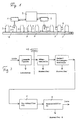
- Figure 1 shows schematically a conveyor belt 6 on which bottles are conveyed standing.
- the bottles are reusable PET bottles, which are then fed to a washing system after the test described above and are then refilled with a drink.
- the test according to the invention uses two test stations 1, 2.
- a strong contamination of the bottle with harmful substances is determined, which means, for example, such substances as gasoline, solvents, paints, insecticides, alcohol etc.
- a gas sample is taken from the bottle by the test station 1, which can be done, for example, by means of a retractable and extendable probe 4, as is shown schematically.
- station 1 for heavy contamination, it may also be sufficient if gas is sucked in above the bottle opening.
- the gas sample taken is analyzed, which is preferably done in a known manner by means of photo-ionization detection.
- a suitable device is, for example, the photo ionization detector model PI 52-02A from HNU Systems, Inc.
- the response threshold is set so that strongly contaminated bottles are reliably detected.
- the information as to whether a bottle is contaminated in this way is sent to a control device 9. Depending on the signal from the test station 1, this controls the test station 2 in such a way that it does not test the bottles identified as soiled.
- control device 9 controls, depending on the test station 1, an ejector 7, shown in broken lines, which is arranged in the conveying direction after the test station 1 and which ejects the bottle, which is recognized as contaminated, from the conveying device or ejects it onto another conveyor track before it exits the test station 2 has reached.
- the test station 2 checks the bottles considered as clean by station 1 again on the presence of harmful substances.
- very high concentrations of harmful substances in the gas sample no longer have to be expected here, which is why a low detection threshold can be selected without fear that a long time between measurements is required to reduce the memory effect.
- measurements can be carried out quickly one after the other, which allows a high bottle throughput.
- a gas sample is also taken from the bottle by means of a retractable and extendable probe 5.
- the measurement is preferably carried out here using a commercially available mass spectrometer, which enables a particularly precise analysis of even minor contaminations and therefore the clear decision as to whether the bottle is still usable or not.
- mass spectrometer enables a particularly precise analysis of even minor contaminations and therefore the clear decision as to whether the bottle is still usable or not.
- unusable bottles are ejected from the conveying path or deflected onto another conveying path by another ejector 8.
- the test station 2 can also be provided with the photo-ionization detector already mentioned.
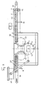
- FIG. 2 schematically shows a top view of a device 40 for testing bottles that works according to the method.
- Returnable returnable bottles are delivered to the device in a disordered manner on a conveyor line 41.
- the bottles are delivered upright to the device and are generally open, ie no longer provided with a lid and not yet washed.
- the bottles 3 With a conveyor and a corresponding back pressure, the bottles 3 are fed to a control star 42, which also forms the line stop, and are delivered to a screw conveyor 43, which conveys the bottles upright in a regularly spaced order.
- a control star 42 which also forms the line stop
- a screw conveyor 43 which conveys the bottles upright in a regularly spaced order.
- several test arrangements can be provided in front of the test station 1, which are explained in detail below with reference to FIG. 3.
- the bottles can be at the correct height and be checked for the presence of a lid or other closure and a residual amount of liquid.
- Unsuitable bottles can be ejected from the screw conveyor by an ejector 11.
- the bottles then arrive at the test station 1, the photo-ionization detector, and, if recognized as soiled, are marked accordingly in the control device or, in the alternative embodiment, are eliminated from the conveying path.
- the bottles 3 pretested in this way pass from the screw 43 onto an inlet carousel 45.
- the bottles are delivered from this inlet carousel 45 to a main carousel 47.
- the test is carried out in test station 2, for example as a mass spectrometric test.
- the main carousel will be able to hold a larger number of bottles to be checked, for example 16 bottles, which are checked by a mass spectrometer arranged above the main carousel.
- the bottles tested pass through an outlet carousel 48 to an outlet screw 49.
- a further ejector 53 is arranged at this outlet screw, which ejects those bottles which the mass spectrometer has identified as contaminated.
- the ejection can take place in various known ways, for example by means of a compressed air jet or by an electromechanically actuated ejection plunger.
- a "gentle" rejection system is preferred, which feeds the bottles to be separated upright to another conveyor line.
- FIG. 3 schematically shows the test steps carried out in the device according to FIG. 3.
- the bottles arriving on the conveyor line arrive at the control star 42, whereby lying bottles bring about a line stop through the star 42.
- the height of each individual bottle is subsequently checked in the feed screw by means of two light barriers. Bottles that are too big or too small are eliminated.
- an ultrasound sensor is used to check whether the bottle cap has been removed from each bottle. Bottles with bottle caps or other closures are discarded.
- a weight sensor is used to check whether there is still a large amount of residual liquid in the bottle. If this is the case, the bottle is eliminated.
- FIG. 4 shows the main carousel 47 from FIG. 2, only two bottle holders and only one bottle 3 being shown.
- the carousel is arranged on a fixed machine table 60 and is rotated by a motor (not shown) via a drive wheel 61.
- the bottles 3 move above a machine-fixed floor guide plate 63 and are each held in the bottle bottom area in an outer guide 64 which runs around the central axis of the carousel and in the bottle neck area in a peripheral outer guide 65.
- the distance between the guides 64 and 65 can be shifted by moving the top Carousel part can be set relative to the lower carousel part, which is represented by the arrow b and by the indicated guide 65 ', which shows the guide 65 in its lower position for a bottle with a lower height.
- a double stroke unit 68 which carries the gas sampling tube 5 for each bottle.
- 16 such double lifting units 68 are provided, the function of which is explained below.
- a gas sampling tube 5 is carried by each double stroke unit 68 and is connected to a central valve head 70 via a flexible hose 71.
- the air extracted from the bottles 3 is distributed over a single line 72, which leads to the mass spectrometer 2, which is only indicated.
- Gas is preferably sucked out of the bottle 3 in the carousel during most of the circulation of each bottle 3, which is done by means of a central vacuum pump (not shown) which is connected to the connection 73 of the valve head 70.
- a central vacuum pump (not shown) which is connected to the connection 73 of the valve head 70.
- One of the gas sampling tubes 5 is then briefly connected to the mass spectrometer 2 in the valve head 70, while in the other time the remaining gas samples are discharged through the connection 73 to the pump. In this way, the influence of the long delivery path from the extraction tube 5 to the valve head 70 on the measuring time is eliminated.
- each closure 90 is only indicated in FIG. 4 below the left extraction tube 5 and is not shown in the right extraction tube, although such a closure must also be provided there.
- the design of the closure will be explained in more detail with reference to FIG. 5.
- the double lifting units 68 each have a lifting plunger 75 which is held displaceably in a guide 76. With its lower end, each lifting plunger engages a lifting curve 69 which is fixed in relation to the carousel part 67. The stroke curve 69 thus causes one when the carousel part 67 rotates Movement of the plunger 75 in the vertical direction.
- the gas sampling tubes 5 are arranged on a carriage 77 which is displaceable along the ram. However, the slide 77 is normally biased by a spring 78 into an end position of its travel on the plunger 75. If the gas sampling tube 5 can be immersed in the bottle without encountering any resistance, there is no displacement of the slide 77 relative to the plunger 75, but the slide 77 follows the plunger movement 75 caused by the lifting cranks 69 and dips into the bottle 3, or withdraws from it.
- the gas sampling tube 5 strikes the closure 90 when the plunger 75 is lowered and therefore cannot be lowered into the bottle 3. In this case, the plunger 75 moves further downwards to carry out the lowering movement, but the gas sampling tube 5 and the slide 77 do not carry out this downward movement. The plunger 75 moves relative to the fixed carriage 77, the spring 78 being tensioned. The gas sampling tube 5 remains blocked above this bottle during the circulation of this bottle, which is blocked by the closure 90, and does not suck in any air from the bottle 3 even in this position, since the closure 90 prevents this.
- the plunger 75 When the plunger 75 is raised, it first moves up relative to the further fixed carriage 77 until the normal position of the carriage 77 on the plunger 75, which is caused by the the spring 78 surrounding stop rod 79 is determined, is reached. As soon as the normal position of the plunger and slide relative to one another has been restored when the plunger 75 is raised by the spring 78, these elements move again synchronously with one another, unless the closure again for the next bottle into which the gas sampling tube 5 has to be immersed 90 prevents such immersion.
- FIG. 5 shows part of the closure 90.
- the carousel part 67 rotating in the direction of the arrow can be seen from above.
- a closure flap 81 which can be rotated about an axis of rotation 80 is provided on this for each bottle position. With 16 bottle positions, 16 such flaps 81 are provided.
- the flaps 82 have a passage opening 82 for the gas sampling tube 5.
- the tube 5 located above the flap 81 may or may not enter the bottle 3 when it is lowered.
- To set the flaps 81 they are first brought into the open position by a reset curve 83 in each revolution, as can be seen in the flap 81 c.
- the flap After this dirty bottle has left the carousel, the flap returns to the Reset curve 83, where it is brought into the open position and subsequently remains in this position, provided the next bottle is a clean bottle, or the flap is closed again when the next bottle 3 assigned to the flap is again a dirty bottle.
- each tube 5 can also be provided with an individually controllable drive.
- the locking mechanism 90 can be dispensed with.
- the gas sampling tube 5 is then controlled by the control unit and driven by its individual drive into the bottle 3 or not, depending on whether a bottle to be tested or a dirty bottle not to be tested enters the carousel.
- the solution shown with the closure mechanism 90 offers, however, in particular the advantage that the respective flap 81 forms a lock for the suction of gas from the bottle 3, which, even if to a small extent, also when the bottle 5 is not retracted Position of the tube 5 can be done if there is no such lock.
Landscapes
- Health & Medical Sciences (AREA)
- Life Sciences & Earth Sciences (AREA)
- Engineering & Computer Science (AREA)
- Chemical & Material Sciences (AREA)
- Immunology (AREA)
- Pathology (AREA)
- Physics & Mathematics (AREA)
- General Physics & Mathematics (AREA)
- Analytical Chemistry (AREA)
- Biochemistry (AREA)
- General Health & Medical Sciences (AREA)
- Biomedical Technology (AREA)
- Mechanical Engineering (AREA)
- Molecular Biology (AREA)
- Food Science & Technology (AREA)
- Medicinal Chemistry (AREA)
- Other Investigation Or Analysis Of Materials By Electrical Means (AREA)
- Investigating Materials By The Use Of Optical Means Adapted For Particular Applications (AREA)
- Automatic Analysis And Handling Materials Therefor (AREA)
- Sampling And Sample Adjustment (AREA)
- Electron Tubes For Measurement (AREA)
- Investigating Strength Of Materials By Application Of Mechanical Stress (AREA)
- Filling Of Jars Or Cans And Processes For Cleaning And Sealing Jars (AREA)
- External Artificial Organs (AREA)
Claims (14)
- Procédé pour détecter la présence de salissures dans des bouteilles récupérables recyclées en vue d'un nouveau remplissage, en particulier de bouteilles en PET, par test de gaz prélevé dans chaque bouteille, les bouteilles étant transportées le long d'un trajet d'avance, caractérisé en ce que le test de chaque bouteille est effectué au moyen d'au moins deux postes de test disposés l'un derrière l'autre le long du trajet d'avance, le premier poste de test possédant un seuil de réponse pour les salissures qui est un multiple du seuil de reconnaissance de salissures du deuxième poste de test, et en ce que, dans le cas de bouteilles dont les salissures ont provoqué la réponse du premier poste de test, le deuxième poste de test est désactivé lors du passage des bouteilles dans ce second poste.
- Procédé suivant la revendication 1, caractérisé en ce que le deuxième poste de test est désactivé en empêchant l'introduction d'un organe de prélèvement de gaz dans la bouteille à tester.
- Procédé suivant la revendication 2, caractérisé en ce que, dans le deuxième poste de test, pour chaque bouteille dont les salissures ont provoqué la réponse du premier poste de test, un élément d'obturation est positionné au-dessus du goulot de la bouteille.
- Procédé pour détecter la présence de salissures dans des bouteilles récupérables recyclées en vue d'un nouveau remplissage, en particulier de bouteilles en PET, par test de gaz prélevé dans chaque bouteille, les bouteilles étant transportées le long d'un trajet d'avance, caractérisé en ce que le test de chaque bouteille est effectué au moyen d'au moins deux postes de test disposés l'un derrière l'autre le long du trajet d'avance, le premier poste de test possédant un seuil de réponse pour les salissures qui est un multiple du seuil de reconnaissance de salissures du deuxième poste de test, et en ce que les bouteilles dont les salissures ont provoqué la réponse du premier poste de test sont évacuées du trajet d'avance avant d'atteindre le deuxième poste de test.
- Procédé suivant l'une des revendications 1 à 4, caractérisé en ce que le premier poste de test prélève dans les bouteilles un échantillon de gaz et teste celui-ci par détection par photo-ionisation, et en ce que le deuxième poste de test prélève dans les bouteilles un autre échantillon de gaz, et teste celui-ci par détection par photo-ionisation.
- Procédé suivant l'une des revendications 1 à 4, caractérisé en ce que le premier poste de test prélève dans les bouteilles un échantillon de gaz et teste celui-ci par détection par photo-ionisation, et en ce que le deuxième poste de test prélève dans les bouteilles un autre échantillon de gaz et teste celui-ci par spectrométrie de masse.
- Procédé suivant l'une des revendications 1 à 6, caractérisé en ce qu'on fait subir à chaque bouteille, avant le premier poste de test, un contrôle de hauteur, et on détecte la présence d'un bouchon ou de liquide résiduel.
- Dispositif pour la mise en oeuvre du procédé suivant l'une quelconque des revendications 1, 2, 3, 5 et 6, caractérisé par un convoyeur pour des bouteilles recyclés, un premier poste de test disposé le long du convoyeur et comportant une première unité de prélèvement d'échantillons gazeux ainsi qu'une première unité de détection, un deuxième poste de test disposé le long du convoyeur derrière le premier poste de test en considérant le sens d'avance des bouteilles, et comprenant une deuxième unité de prélèvement d'échantillons gazeux ainsi qu'une deuxième unité de détection, et par une unité de commande au moyen de laquelle la deuxième unité de prélèvement d'échantillons de gaz peut être désactivée en fonction du signal de sortie de la première unité de détection.
- Dispositif suivant la revendication 8, caractérisé en ce que, dans la région du deuxième poste de test, le convoyeur est réalisé sous la forme d'un carrousel, une unité de prélèvement d'échantillons gazeux, qui peut être abaissée à l'intérieur des bouteilles, étant associée à chaque bouteille à tester.
- Dispositif suivant la revendication 9, caractérisé en ce que chaque unité de prélèvement d'échantillons gazeux pouvant être abaissée comprend un tube d'échantillonnage de gaz qui peut être abaissé en position de prélèvement au moyen d'une première unité respective de déplacement vertical, et en ce que l'abaissement de chaque tube peut être bloqué par un volet d'obturation, le tube d'échantillonnage étant désaccouplé du mouvement de descente de la première unité de déplacement vertical par une seconde unité de déplacement vertical lorsque son mouvement vers le bas est bloqué.
- Dispositif suivant la revendication 10, caractérisé en ce que chaque volet d'obturation est monté pivotant autour d'un axe sur une partie rotative du carrousel, et peut être amené par pivotement en position d'ouverture par une came de rappel fixe et être amené individuellement en position de fermeture par une came de manoeuvre fixe actionnable par l'unité de commande.
- Dispositif pour la mise en oeuvre du procédé suivant la revendication 4, caractérisé par un convoyeur pour des bouteilles recyclées et par un premier poste de test disposé le long du convoyeur et comprenant une unité de prélèvement d'échantillons gazeux et un détecteur par photo-ionisation, par un deuxième poste de test disposé le long du convoyeur derrière le premier poste de test en considérant le sens d'avance des bouteilles, ce deuxième poste comprenant une autre unité de prélèvement d'échantillons gazeux et une unité de détection, ainsi que par un dispositif (7) d'évacuation des bouteilles du trajet d'avance, disposé entre les unités de prélèvement d'échantillons gazeux.
- Dispositif suivant la revendication 12, caractérisé en ce que l'unité de détection comprend un détecteur par photo-ionisation.
- Dispositif suivant la revendication 12, caractérisé en ce que l'unité de détection comprend un spectromètre de masse.
Applications Claiming Priority (8)
| Application Number | Priority Date | Filing Date | Title |
|---|---|---|---|
| CH216692 | 1992-07-09 | ||
| CH2166/92 | 1992-07-09 | ||
| CH415/93 | 1993-02-11 | ||
| CH41693 | 1993-02-11 | ||
| CH41593 | 1993-02-11 | ||
| CH416/93 | 1993-02-11 | ||
| CH656/93 | 1993-03-04 | ||
| CH656/93A CH684631A5 (de) | 1993-03-04 | 1993-03-04 | Verfahren und Vorrichtung zum Prüfen von Flaschen auf das Vorhandensein von Verunreinigungen. |
Publications (2)
| Publication Number | Publication Date |
|---|---|
| EP0578146A1 EP0578146A1 (fr) | 1994-01-12 |
| EP0578146B1 true EP0578146B1 (fr) | 1995-08-16 |
Family
ID=27427867
Family Applications (1)
| Application Number | Title | Priority Date | Filing Date |
|---|---|---|---|
| EP93110577A Expired - Lifetime EP0578146B1 (fr) | 1992-07-09 | 1993-07-02 | Procédé et dispositif pour détecter la présence de salissures dans des bouteilles |
Country Status (10)
| Country | Link |
|---|---|
| US (2) | US5520060A (fr) |
| EP (1) | EP0578146B1 (fr) |
| JP (1) | JPH0789103B2 (fr) |
| AT (1) | ATE126588T1 (fr) |
| BR (1) | BR9302796A (fr) |
| CA (1) | CA2100036A1 (fr) |
| DE (1) | DE59300479D1 (fr) |
| DK (1) | DK0578146T3 (fr) |
| MX (1) | MX9304132A (fr) |
| NO (1) | NO932495L (fr) |
Families Citing this family (22)
| Publication number | Priority date | Publication date | Assignee | Title |
|---|---|---|---|---|
| NZ253476A (en) * | 1992-06-01 | 1995-11-27 | Coca Cola Co | Contaminants remaining in empty beverage container determined from wavelength of radiation from chemiluminescence of volatiles with reactant |
| EP0647847A1 (fr) * | 1993-09-14 | 1995-04-12 | Elpatronic Ag | Utilisation d'un spectromètre de masse à ionisation de récipients |
| EP0722789A1 (fr) * | 1995-01-17 | 1996-07-24 | Elpatronic Ag | Méthode pour tester le fonctionnement d'un détecteur dans une station d'inspection |
| EP0736763A1 (fr) * | 1995-04-03 | 1996-10-09 | Elpatronic Ag | Dispositif pour l'examen de récipients |
| EP0747690A1 (fr) * | 1995-06-08 | 1996-12-11 | Elpatronic Ag | Dispositif de contrÔle des récipients |
| US5656786A (en) * | 1996-05-03 | 1997-08-12 | Ico, Inc. | Oilfield tubular inspection method and apparatus |
| EP0837309A3 (fr) * | 1996-10-18 | 1999-03-10 | SANYO ELECTRIC Co., Ltd. | Procédé et système d'essai de la performance d'ensembles frigorifiques |
| EP0837310A3 (fr) * | 1996-10-18 | 1999-03-10 | SANYO ELECTRIC Co., Ltd. | Système d'essai de la qualité d'appareils électriques |
| US5929318A (en) * | 1997-05-02 | 1999-07-27 | Illinois Instruments, Inc. | System and method for sensing low levels of a particular gas in an atmosphere |
| US6225633B1 (en) * | 1998-10-22 | 2001-05-01 | Rae Systems, Inc. | Photo-ionization detector for volatile gas measurement and a method for self-cleaning the same |
| US6734435B2 (en) | 2001-05-29 | 2004-05-11 | Rae Systems, Inc. | Photo-ionization detector and method for continuous operation and real-time self-cleaning |
| DE102006053673A1 (de) * | 2006-11-13 | 2008-05-15 | Khs Ag | Verfahren zur Inspektion von Flaschen oder dergleichen Behälter sowie Messstation für eine Inspektions- oder Kontrollstrecke für Flaschen oder dergleichen Behälter |
| DE102009003847B4 (de) * | 2009-04-29 | 2025-07-10 | Krones Aktiengesellschaft | Vorrichtung und Verfahren zum Ausleiten von Objekten von einer sich bewegenden Transporteinrichtung |
| JP2012117899A (ja) * | 2010-11-30 | 2012-06-21 | Mitsubishi Materials Techno Corp | 容器検査方法及び容器検査装置 |
| DE102012214582A1 (de) * | 2012-08-16 | 2014-02-20 | Adelholzener Alpenquellen Gmbh | Detektion von Flaschen mit Fehlgeschmack |
| US9752965B2 (en) | 2013-10-16 | 2017-09-05 | Sensigent LLC | Apparatus and method for fast sampling and measurement |
| US10317878B2 (en) * | 2015-03-30 | 2019-06-11 | Lm3 Technologies, Inc. | System and method for assembling and/or testing articles |
| US11598696B2 (en) * | 2019-06-14 | 2023-03-07 | Emerald Coast Manufacturing, LLC | Method and apparatus for sampling liquid |
| CN110803355B (zh) * | 2019-11-21 | 2022-03-29 | 中国电子科技集团公司第四十八研究所 | 一种瓶类垃圾自动处理装置及处理方法 |
| DE102021107329A1 (de) | 2021-03-24 | 2022-09-29 | Krones Aktiengesellschaft | Vorrichtung und Verfahren zum Reinigen und Inspizieren von Behältnissen mit Gasanalyseeinrichtungen |
| IT202100025184A1 (it) | 2021-09-30 | 2023-03-30 | Ft System Srl | Sistema di ispezione per contenitori e relativo metodo di ispezione |
| EP4331737A1 (fr) * | 2022-08-30 | 2024-03-06 | Sidel Participations | Machine à laver de récipients vides conçue pour être remplie d'un produit versable et procédé associé |
Family Cites Families (13)
| Publication number | Priority date | Publication date | Assignee | Title |
|---|---|---|---|---|
| US3094219A (en) * | 1962-01-29 | 1963-06-18 | 42 Products Ltd Inc | Portable wire rack for bottles |
| US3211290A (en) * | 1962-09-10 | 1965-10-12 | Charles F Strickling | Bottle selector |
| FR1344848A (fr) * | 1963-01-24 | 1963-11-29 | Atlas Mess Und Analysentechnik | Dispositif obturable pour l'admission d'un gaz dans une enceinte sous vide très poussé |
| US3321954A (en) * | 1966-07-20 | 1967-05-30 | Nat Distillers Chem Corp | Contaminant detection apparatus |
| DE1598415A1 (de) * | 1967-02-01 | 1971-04-01 | Walter Eugster Maschinenhandel | Verfahren zur Foerderung von Luftproben in Raumluftkontrollanlagen und Einrichtung zur Durchfuehrung des Verfahrens |
| DE3023211A1 (de) * | 1979-06-28 | 1981-01-22 | Ti Fords Ltd | Verfahren und vorrichtung zur ermittlung einer waesserigen fluessigkeit in flaschen und behaeltern |
| DE3621976A1 (de) * | 1986-07-01 | 1988-01-07 | Kronseder Maschf Krones | Verfahren und vorrichtung zum pruefen von leeren getraenkeflaschen oder dgl. |
| DE3624419A1 (de) * | 1986-07-19 | 1988-01-28 | Staudacher Horst | Vorrichtung zur objektkontrolle |
| US4858768A (en) * | 1986-08-04 | 1989-08-22 | The Coca-Cola Company | Method for discrimination between contaminated and uncontaminated containers |
| DE8806138U1 (de) * | 1987-08-24 | 1988-09-01 | Datz, Falk Wilhelm, 56626 Andernach | Vorrichtung zum mehrstufigen Behandeln von Getränke-Rücklaufflaschen |
| US4858767A (en) * | 1987-09-02 | 1989-08-22 | The Coca-Cola Company | Plastic container inspection process |
| US5116764A (en) * | 1988-07-26 | 1992-05-26 | Raymond Annino | Dual-column, dual-detector gas detector and analyzer |
| US5350565A (en) * | 1992-12-03 | 1994-09-27 | Photovac Centre, Inc. | System for the detection of noxious contaminants in beverage and potable water containers |
-
1993
- 1993-07-02 DE DE59300479T patent/DE59300479D1/de not_active Expired - Fee Related
- 1993-07-02 AT AT93110577T patent/ATE126588T1/de active
- 1993-07-02 DK DK93110577.9T patent/DK0578146T3/da not_active Application Discontinuation
- 1993-07-02 EP EP93110577A patent/EP0578146B1/fr not_active Expired - Lifetime
- 1993-07-07 US US08/088,432 patent/US5520060A/en not_active Expired - Fee Related
- 1993-07-07 CA CA002100036A patent/CA2100036A1/fr not_active Abandoned
- 1993-07-08 BR BR9302796A patent/BR9302796A/pt not_active Application Discontinuation
- 1993-07-08 NO NO932495A patent/NO932495L/no unknown
- 1993-07-09 MX MX9304132A patent/MX9304132A/es not_active IP Right Cessation
- 1993-07-09 JP JP5170164A patent/JPH0789103B2/ja not_active Expired - Lifetime
-
1995
- 1995-06-07 US US08/471,872 patent/US5571978A/en not_active Expired - Fee Related
Also Published As
| Publication number | Publication date |
|---|---|
| US5571978A (en) | 1996-11-05 |
| MX9304132A (es) | 1994-02-28 |
| JPH06160304A (ja) | 1994-06-07 |
| JPH0789103B2 (ja) | 1995-09-27 |
| EP0578146A1 (fr) | 1994-01-12 |
| DE59300479D1 (de) | 1995-09-21 |
| BR9302796A (pt) | 1994-02-16 |
| CA2100036A1 (fr) | 1994-01-10 |
| DK0578146T3 (da) | 1995-12-04 |
| US5520060A (en) | 1996-05-28 |
| NO932495L (no) | 1994-01-10 |
| NO932495D0 (no) | 1993-07-08 |
| ATE126588T1 (de) | 1995-09-15 |
Similar Documents
| Publication | Publication Date | Title |
|---|---|---|
| EP0578146B1 (fr) | Procédé et dispositif pour détecter la présence de salissures dans des bouteilles | |
| EP0579952B2 (fr) | Procédé et dispositif pour contrôler l'état de propieté de bouteilles | |
| DE4214958C2 (de) | Kontinuierlich arbeitende Inspektionsmaschine für Gefäße | |
| EP2850416B1 (fr) | Procédé et dispositif de contrôle de bouteilles vides | |
| EP0993418A1 (fr) | Procede et dispositif de fermeture de bouteilles par des bouchons steriles | |
| DE2801387A1 (de) | Sortiergeraet | |
| DE102016122632A1 (de) | Vorrichtung zum Aussondern eines Artikels | |
| EP0648151A1 (fr) | Procede et dispositif pour trier des capsules. | |
| DE2820661A1 (de) | Verfahren und vorrichtung zur feststellung von fremdkoerpern in fluessigkeiten | |
| DE10007627A1 (de) | Verfahren und Vorrichtung zum Ausleiten liegender Gefäße | |
| DE3930917A1 (de) | Vorrichtung zum absondern von zigaretten | |
| DE2951424A1 (de) | Verfahren und einrichtung zum pruefen der unversehrtheit einer folge von behaeltern | |
| EP3110701B1 (fr) | Dispositif d'inspection de recipients | |
| EP0579055A1 (fr) | Procédé et dispositif pour contrôler l'état de propieté à l'aide de la spectrométrie de masse de bouteilles | |
| DE1473688B2 (de) | Verfahren zur zerstoerungsfreien pruefung von glaserzeugnissen und vorrichtung zur durchfuehrung des verfahrens | |
| CH684631A5 (de) | Verfahren und Vorrichtung zum Prüfen von Flaschen auf das Vorhandensein von Verunreinigungen. | |
| WO2016030543A1 (fr) | Dispositif et procédé d'impression sur des contenants comprenant une détection d'erreurs | |
| EP3482187B1 (fr) | Dispositif et procédé pour analyser des récipients quant à la présence de corps étrangers | |
| DE4225984A1 (de) | Verfahren und Vorrichtung zur Inspektion von transportierten Behältern | |
| DE19505474C2 (de) | Verfahren und Vorrichtung zum Prüfen von Flaschen aus Kunststoff auf Kontaminationen | |
| DE4332645A1 (de) | Getränkefüllmaschine | |
| DE3007540A1 (de) | Vorrichtung zum pruefen und aussortieren von fremdflaschen | |
| DE2525919C2 (de) | Prüfanlage für Getränkeflaschen | |
| DE3840005A1 (de) | Verfahren und einrichtung zum pruefen von hohlglaskoerpern auf enthaltene einschluesse | |
| EP3910311A1 (fr) | Dispositif et procédé d'inspection des contenants au niveau de corps étrangers |
Legal Events
| Date | Code | Title | Description |
|---|---|---|---|
| PUAI | Public reference made under article 153(3) epc to a published international application that has entered the european phase |
Free format text: ORIGINAL CODE: 0009012 |
|
| 17P | Request for examination filed |
Effective date: 19931028 |
|
| AK | Designated contracting states |
Kind code of ref document: A1 Designated state(s): AT BE CH DE DK FR GB IT LI NL SE |
|
| 17Q | First examination report despatched |
Effective date: 19941223 |
|
| GRAA | (expected) grant |
Free format text: ORIGINAL CODE: 0009210 |
|
| RAP1 | Party data changed (applicant data changed or rights of an application transferred) |
Owner name: ELPATRONIC AG |
|
| AK | Designated contracting states |
Kind code of ref document: B1 Designated state(s): AT BE CH DE DK FR GB IT LI NL SE |
|
| PG25 | Lapsed in a contracting state [announced via postgrant information from national office to epo] |
Ref country code: IT Free format text: LAPSE BECAUSE OF FAILURE TO SUBMIT A TRANSLATION OF THE DESCRIPTION OR TO PAY THE FEE WITHIN THE PRESCRIBED TIME-LIMIT;WARNING: LAPSES OF ITALIAN PATENTS WITH EFFECTIVE DATE BEFORE 2007 MAY HAVE OCCURRED AT ANY TIME BEFORE 2007. THE CORRECT EFFECTIVE DATE MAY BE DIFFERENT FROM THE ONE RECORDED. Effective date: 19950816 Ref country code: GB Effective date: 19950816 Ref country code: FR Free format text: THE PATENT HAS BEEN ANNULLED BY A DECISION OF A NATIONAL AUTHORITY Effective date: 19950816 |
|
| REF | Corresponds to: |
Ref document number: 126588 Country of ref document: AT Date of ref document: 19950915 Kind code of ref document: T |
|
| REF | Corresponds to: |
Ref document number: 59300479 Country of ref document: DE Date of ref document: 19950921 |
|
| REG | Reference to a national code |
Ref country code: DK Ref legal event code: T3 |
|
| EN | Fr: translation not filed | ||
| GBV | Gb: ep patent (uk) treated as always having been void in accordance with gb section 77(7)/1977 [no translation filed] |
Effective date: 19950816 |
|
| PLBE | No opposition filed within time limit |
Free format text: ORIGINAL CODE: 0009261 |
|
| STAA | Information on the status of an ep patent application or granted ep patent |
Free format text: STATUS: NO OPPOSITION FILED WITHIN TIME LIMIT |
|
| 26N | No opposition filed | ||
| PGFP | Annual fee paid to national office [announced via postgrant information from national office to epo] |
Ref country code: BE Payment date: 19970624 Year of fee payment: 5 Ref country code: AT Payment date: 19970624 Year of fee payment: 5 |
|
| PGFP | Annual fee paid to national office [announced via postgrant information from national office to epo] |
Ref country code: SE Payment date: 19970625 Year of fee payment: 5 |
|
| PGFP | Annual fee paid to national office [announced via postgrant information from national office to epo] |
Ref country code: DK Payment date: 19970714 Year of fee payment: 5 |
|
| PGFP | Annual fee paid to national office [announced via postgrant information from national office to epo] |
Ref country code: CH Payment date: 19970715 Year of fee payment: 5 |
|
| PGFP | Annual fee paid to national office [announced via postgrant information from national office to epo] |
Ref country code: DE Payment date: 19970717 Year of fee payment: 5 |
|
| PGFP | Annual fee paid to national office [announced via postgrant information from national office to epo] |
Ref country code: NL Payment date: 19970731 Year of fee payment: 5 |
|
| PG25 | Lapsed in a contracting state [announced via postgrant information from national office to epo] |
Ref country code: AT Free format text: LAPSE BECAUSE OF NON-PAYMENT OF DUE FEES Effective date: 19980702 |
|
| PG25 | Lapsed in a contracting state [announced via postgrant information from national office to epo] |
Ref country code: SE Free format text: LAPSE BECAUSE OF NON-PAYMENT OF DUE FEES Effective date: 19980703 |
|
| PG25 | Lapsed in a contracting state [announced via postgrant information from national office to epo] |
Ref country code: LI Free format text: LAPSE BECAUSE OF NON-PAYMENT OF DUE FEES Effective date: 19980731 Ref country code: DK Free format text: LAPSE BECAUSE OF NON-PAYMENT OF DUE FEES Effective date: 19980731 Ref country code: CH Free format text: LAPSE BECAUSE OF NON-PAYMENT OF DUE FEES Effective date: 19980731 Ref country code: BE Free format text: LAPSE BECAUSE OF NON-PAYMENT OF DUE FEES Effective date: 19980731 |
|
| BERE | Be: lapsed |
Owner name: ELPATRONIC A.G. Effective date: 19980731 |
|
| PG25 | Lapsed in a contracting state [announced via postgrant information from national office to epo] |
Ref country code: NL Free format text: LAPSE BECAUSE OF NON-PAYMENT OF DUE FEES Effective date: 19990201 |
|
| REG | Reference to a national code |
Ref country code: CH Ref legal event code: PL |
|
| EUG | Se: european patent has lapsed |
Ref document number: 93110577.9 |
|
| NLV4 | Nl: lapsed or anulled due to non-payment of the annual fee |
Effective date: 19990201 |
|
| PG25 | Lapsed in a contracting state [announced via postgrant information from national office to epo] |
Ref country code: DE Free format text: LAPSE BECAUSE OF NON-PAYMENT OF DUE FEES Effective date: 19990501 |
|
| REG | Reference to a national code |
Ref country code: DK Ref legal event code: EBP |