EP0578268A1 - Verbindungsvorrichtung für eine Sprossenkreuzkonstruktion - Google Patents
Verbindungsvorrichtung für eine Sprossenkreuzkonstruktion Download PDFInfo
- Publication number
- EP0578268A1 EP0578268A1 EP93112155A EP93112155A EP0578268A1 EP 0578268 A1 EP0578268 A1 EP 0578268A1 EP 93112155 A EP93112155 A EP 93112155A EP 93112155 A EP93112155 A EP 93112155A EP 0578268 A1 EP0578268 A1 EP 0578268A1
- Authority
- EP
- European Patent Office
- Prior art keywords
- clamping piece
- pin
- hole
- cross
- strut
- Prior art date
- Legal status (The legal status is an assumption and is not a legal conclusion. Google has not performed a legal analysis and makes no representation as to the accuracy of the status listed.)
- Granted
Links
Images


Classifications
-
- E—FIXED CONSTRUCTIONS
- E06—DOORS, WINDOWS, SHUTTERS, OR ROLLER BLINDS IN GENERAL; LADDERS
- E06B—FIXED OR MOVABLE CLOSURES FOR OPENINGS IN BUILDINGS, VEHICLES, FENCES OR LIKE ENCLOSURES IN GENERAL, e.g. DOORS, WINDOWS, BLINDS, GATES
- E06B3/00—Window sashes, door leaves, or like elements for closing wall or like openings; Layout of fixed or moving closures, e.g. windows in wall or like openings; Features of rigidly-mounted outer frames relating to the mounting of wing frames
- E06B3/66—Units comprising two or more parallel glass or like panes permanently secured together
- E06B3/663—Elements for spacing panes
- E06B3/667—Connectors therefor
-
- E—FIXED CONSTRUCTIONS
- E06—DOORS, WINDOWS, SHUTTERS, OR ROLLER BLINDS IN GENERAL; LADDERS
- E06B—FIXED OR MOVABLE CLOSURES FOR OPENINGS IN BUILDINGS, VEHICLES, FENCES OR LIKE ENCLOSURES IN GENERAL, e.g. DOORS, WINDOWS, BLINDS, GATES
- E06B3/00—Window sashes, door leaves, or like elements for closing wall or like openings; Layout of fixed or moving closures, e.g. windows in wall or like openings; Features of rigidly-mounted outer frames relating to the mounting of wing frames
- E06B3/66—Units comprising two or more parallel glass or like panes permanently secured together
- E06B3/6604—Units comprising two or more parallel glass or like panes permanently secured together comprising false glazing bars or similar decorations between the panes
-
- E—FIXED CONSTRUCTIONS
- E06—DOORS, WINDOWS, SHUTTERS, OR ROLLER BLINDS IN GENERAL; LADDERS
- E06B—FIXED OR MOVABLE CLOSURES FOR OPENINGS IN BUILDINGS, VEHICLES, FENCES OR LIKE ENCLOSURES IN GENERAL, e.g. DOORS, WINDOWS, BLINDS, GATES
- E06B3/00—Window sashes, door leaves, or like elements for closing wall or like openings; Layout of fixed or moving closures, e.g. windows in wall or like openings; Features of rigidly-mounted outer frames relating to the mounting of wing frames
- E06B3/68—Window bars
-
- E—FIXED CONSTRUCTIONS
- E06—DOORS, WINDOWS, SHUTTERS, OR ROLLER BLINDS IN GENERAL; LADDERS
- E06B—FIXED OR MOVABLE CLOSURES FOR OPENINGS IN BUILDINGS, VEHICLES, FENCES OR LIKE ENCLOSURES IN GENERAL, e.g. DOORS, WINDOWS, BLINDS, GATES
- E06B3/00—Window sashes, door leaves, or like elements for closing wall or like openings; Layout of fixed or moving closures, e.g. windows in wall or like openings; Features of rigidly-mounted outer frames relating to the mounting of wing frames
- E06B3/96—Corner joints or edge joints for windows, doors, or the like frames or wings
- E06B3/99—Corner joints or edge joints for windows, doors, or the like frames or wings for continuous frame members crossing each other with out interruption
Definitions
- the invention relates to a connecting device for a crossbar construction of the type specified in the preamble of claim 1.
- Rungs in double glazing are between two panes of e.g. B. windows arranged.
- the rungs consist of hollow profile rods, the z. B. are plugged together by means of cross-connectors and are connected to the spacer frame of the double glazing with connecting plugs.
- the rungs either have the metal color or they are coated with paint, whereby the color of the rungs is usually matched to the color of the window frame.
- Connecting devices for example the connecting device of the type mentioned at the outset, which is known from DE 36 38 355 A1, are used to connect the cross struts to the main strut.
- a clamping piece is used, the pin receiving hole of which is a cylindrical fitting bore for a cylindrical connecting pin, the connecting pin and fitting bore being additionally provided with longitudinal grooves. If the pin is inserted into the hole of the clamping piece inserted in a cross strut, there is a risk that the clamping piece will be pushed into the cross strut, whereby the desired positive connection of the cross strut to the main strut by means of the clamping piece is no longer guaranteed.
- the clamping piece with its side edges does not lie completely against the inner wall of the respective cross strut, because laterally projecting lugs are formed at the front end of the clamping piece in the insertion direction, which give rise to a point contact connection between the clamping piece and cross strut.
- the present invention has for its object to develop the clamping piece of the generic connecting device so that the position of the clamping piece in the cross strut is ensured when the pin is inserted into the clamping piece and also ensures that the clamping piece remains permanently in its position in the cross strut.
- a window 1 is shown with double glazing and interposed cross bar construction for rung windows.
- the invention relates not only to cross bar constructions for rung windows with double glazing, but also to cross bar constructions for double glazing par excellence.
- a window 1 with insulating glazing generally has a window frame 2, at least two glass panes 3 arranged at a distance and stored in the window frame 2, and a spacer frame 4 which holds the glass panes 3 at a distance and is filled with desiccant.
- Rungs or struts 5 are arranged in the space between the glass panes 3.
- the rungs 5 consist of hollow profile bars made of metal with a longitudinal weld 12a, which are assembled to form an intersection. At the crossing points, the rungs 5 are assembled in a manner known per se with cross connecting pieces (not shown). Connection plugs take over the mounting of the rungs 5 on the spacer frame 4 in a manner known per se.
- Rungs 5 can have different hollow profile cross-sectional shapes.
- a common profile is shown which has side walls 6 arranged parallel to the glass panes 3 and end walls 7 running transversely to the side walls 6.
- the end walls 7 are narrower than the side walls 6, which is why a preferably fillet-shaped transition region 6a is provided between the walls 6 and 7.
- a longitudinal profile indentation 8, 8b or groove-shaped indentations, 9, 9a is profiled in both end walls 7, expediently in the longitudinal center thereof.
- the profile indentations 8, 8b have the same shape and are arranged in mirror image to one another.
- the depth of each groove 9, 9a is z. B. 1/8 to 1/10 of the height of the profile (distance between the end walls 7).
- the width of the groove 9, 9a should be as small as possible, but in any case so small that the bottom of the groove remains invisible from the outside.
- the side walls 8a of the grooves 9, 9a preferably lie against one another.
- the rungs or struts 5 are each cut to the required length by hollow profile rods 11.
- the hollow profile rods 11 are made of a relatively thin metal strip, e.g. B. formed of aluminum, wherein the longitudinal edges 12 of the metal strip are bent towards each other, so that a closed tube 11a is formed.
- the butt edges or longitudinal edges 12 are welded together, so that a weld seam 12a is formed.
- the subsequent profiling produces the grooves 9, 9a in such a way that the weld seam 12a is displaced into the interior 5a of the profile and becomes invisible. So that the rung 5 looks uniform, it is provided according to an expedient embodiment of the invention that the area of the tube 11a opposite the groove 9 with the weld seam 12 is grooved in the same way and contains the grooving 9a.
- the rung 5 is preferably made of aluminum.
- the wall thickness of the rung is in particular approximately 0.4 to 0.6 mm.
- the outer lateral surface of the rung preferably carries a color layer 6c or is anodized.
- the starting material is a relatively wide metal strip 13, which is pulled off from a broadband coil 14.
- the metal strip 13 consists, for. B. made of aluminum and carries a relatively thin layer of paint 6c on the outside 13a.
- the metal strip 13 is first cut longitudinally into a plurality of strips 15 during the pulling process, from which preferably hollow profile rods 11 are z. B. formed by roll deformation and / or embossing.
- the strips 15 can also be rolled up and further processed later.
- the hollow profiles 11 which are formed from the strips 15 can have the same or different cross-sectional shapes. Likewise, the strips 15 can be the same width or different widths.
- the division of the metal strip 13 into a plurality of strips 15 by longitudinal cuts 16 takes place at a processing station A which the metal strip 13 passes through when it is pulled off.
- a processing station B with shaping tools (not shown) behind the processing station A, in which the strip 15 forms a z. B. is formed in cross-section circular tube 11 a with abutting longitudinal edges 12.
- the color layer 6c is located on the outer surface of the tube.
- the longitudinal edges 12 are welded to the weld seam 12a, preferably by laser welding.
- the continuously produced hollow profile rods 11 are cut to suitable commercial lengths and are available to the manufacturer of insulating glazing as an intermediate product.
- the manufacturer cuts the rungs 5 from the hollow profile rod 11 and forms the desired rung configurations for double glazing.
- the manufacturing process it follows from the foregoing to provide at least one profile indentation to make a weld seam invisible and, for optical reasons, suggests arranging at least one further profile indentation in mirror image for the profile indentation with the weld seam.
- the weld seam does not have to be arranged on one end face. Rather, it can e.g. B. are also on a side wall if the visual requirements for the rung profile allow this.
- FIG. 4 shows an exemplary embodiment of a rung cross construction which comprises a hollow profile 101 made of sheet metal serving as the main strut or rung, two vertically attached hollow profile cross struts 102 and an obliquely attached hollow profile cross strut 103.
- the struts 101, 102 and 103 are manufactured using the rolling method and are of identical design. The rolling of the sheet metal starting material, from which the profiles are made, is carried out in such a way that an inner one lies on both sides of the profile Bead or fold 104 is formed, which contributes to the stability of the profiles.
- the special cross-sectional shape of the struts 101, 102 and 103 can be seen, for example, from FIG.
- FIG. 5 shows a side view of the left half of the rung construction in FIG. 4, specifically a view of the narrow side of the two cross struts on the left in FIG. 4 102, which, like the cross strut 103, are cut off at their connecting ends by contour milling such that there are upper and lower sections 105 and 105 'which grip the main strut 101 laterally overlapping.
- 5 shows a view of the main strut 101 which corresponds to a profile cross section.
- the two lateral beads 104 are visible, which are arranged in a plane running perpendicular to the plane of the drawing, which represents one of the two mirror symmetry planes of the struts 101, 102 and 103.
- the second mirror plane of symmetry runs perpendicular to the former through the two broad sides of the profile.
- the profile broad sides comprise two head surfaces 106 and 106 'running parallel to one another and two inclined surfaces 107 and 107' which adjoin the sides of the profile and which slope away to the narrow profile sides and which are concavely curved.
- the contour of the narrow profile sides results from the internal bead formation as a rounded transition 108 and 108 'from the inclined surfaces 107 and 107' to the beads 104 and 104 '.
- the contour milling at the connecting ends of the cross struts 102 and the cross strut 103 is selected such that a projecting part 109 and 109 'of the head surface of these struts, when the cross strut is attached to the main strut, on the transition edge of its head surface 106 or 106' to the adjoining inclined surface 107 or 107 'abuts.
- the front edge of the projecting part 109 or 109 ' accordingly runs straight, specifically perpendicular to the longitudinal axis of the strut.
- retreating edges 110 adjoin the projecting part 109 or 109 ', which, in the case of cross struts attached to the main strut 101, adjoin with their cut edges to the convex inclined surfaces 107 and 107'.
- the oblique edges 110 extend the cross strut connection ends up to their narrow sides, which are trimmed straight in such a way that they abut the narrow sides of the main strut 101.
- the shape of the hollow profile struts described above is intended to give an optical impression that is present in real rungs. However, this shape is not mandatory. Rather, all possible, essentially rectangular cross-sectional shapes can be used.
- a skeleton structure is selected which allows the wall thickness of the hollow-profile struts to be made significantly less than in the case of conventional hollow-profile struts which are used for cross-bar constructions.
- the skeleton structure described in more detail below allows profiles with a wall thickness which is up to 10 times less than that of previous rung cross constructions to be used.
- FIGS. 4 and 5 An element of the skeleton structure is shown in FIGS. 4 and 5, namely a connecting pin 111.
- the connecting pin 111 passes through the main strut 101 in the transverse direction, the narrow side walls of which are provided with push-through openings 112, as can be seen, for example, from FIG. 6, which shows an exploded view of the elements 4, wherein the connecting pins 111 are inserted into clamping pieces 113 designed as clamping pieces, which are inserted into the connecting ends of the cross struts in the manner described in more detail below.
- the clamping piece is designed as a solid body, the contour of which, as can best be seen from the cross-sectional representation of FIG. 3, is adapted to the inner wall contour of the profiles.
- the clamping pieces 113 are complementary to the hollow profiles and have two flat, opposing head surfaces 114 and 114 'and laterally adjoining inclined surfaces 115 and 115' which are convexly curved to the inclined surfaces 107 of the hollow profiles.
- a bore or a hole 117 is formed in the clamping piece center, which serves to receive the connecting pin 111 and has a cross-sectional shape that is matched exactly to that of the connecting pin.
- the cross-sectional shape shown in FIG. 9 is preferred, namely a square cross section of the bore 117 and a corresponding square cross section of the connecting pin 111.
- the clamping piece 113 In order to ensure a tight fit of the connecting pin 111 in the pin receiving bore 117 of the clamping piece 113, and at the same time a tight fit of the clamping piece 111 in the connecting end section of the cross struts, the clamping piece 113, as best shown in FIG. 8, is designed in the manner of a plastic dowel .
- the full body clamping piece 113 is provided in the longitudinal direction with a slot 118 which extends in the direction of the central longitudinal axis of the clamping piece 113.
- the base of the slot 118 lies in the front third of the fitting bore 117 for the pin 111, which bore also extends along the longitudinal center axis of the clamping piece 113, with a longitudinal extent which corresponds to approximately two thirds of the length of the clamping piece 113.
- the fitting bore 117 is designed as a blind hole. Starting from its base in the front part of the fitting bore 117 in the pin insertion direction, the slot opens towards the opposite end of the clamping piece 113 with an angle ⁇ located in the plane of the drawing, as can be seen from the left half of FIG. 8. The right half of FIG.
- the clamping piece 113 is tapered at an angle ⁇ at its front end in its insertion direction.
- it has sloping side wall parts 120. These are preferably formed both on the side walls 116 and on the head surfaces 114 and, if appropriate, also on the inclined surfaces 115.
- This wedge-shaped design of the front clamping piece allows, in particular in view of the spread design of the clamping piece, a simplified insertion into the connection end of the respective cross strut.
- the clamping piece 113 is widened, also by inclined surfaces, namely through the surfaces 120, which are designed to be complementary to the inclined surfaces 120. A particularly intimate press contact of the clamping piece 113 is achieved at its outer end. Also between the inclined surfaces 122 at the rear and the inclined surfaces 120 at the front end of the clamping piece 113 extend obliquely extending wall parts 123 in the region of the side walls 116. These extend at an angle ⁇ which is half the opening angle ⁇ of the slot 118, and when the clamping piece 113 is inserted into a cross hollow profile, these wall parts 123 assume a parallel orientation to the profile side walls, analogously to a plastic expansion dowel.
- the variant of the clamping piece 113 shown in FIG. 6 corresponds to the design of the clamping piece from FIG. 8 with the difference that the inclined walls 122 located at the front are not provided in the variant from FIG. 6, and with the difference that the longitudinal slot 118 extends up to close to the pin insertion end wall of the clamping piece 113.
- the clamping piece 113 is shown in FIG. 6 in the state it is in when it is inserted into the hollow profile 102, that is to say after overcoming the original spread shape of the clamping piece 113, as shown in the left half of FIG. 8.
- the front end face of the clamping piece 113 is flush with the edges of the recessed narrow sides of the cross struts. This is the basis of the U-shaped profile cross-section when looking at the narrow side of the profile connection end. As a result, a large-area support of the front clamping piece end face is achieved on the opposite narrow side of the main hollow profile. From Fig. 7 it can also be seen that the length of the connecting pin 111 and the depth of the fitting bores 117 are selected so that the pin and clamping pieces form a rigid and highly rigid skeleton when the pin is fully inserted into the clamping pieces, without the hollow profiles 101 and 102 also being used enter into a passport connection.
- the transverse hollow struts 102 overlap the main strut 101 in a visually correct manner, but the hollow profile parts do not exert force on one another. Rather, the hollow profiles form a kind of skin that serves as a veneer for the skeletal structure and is not exposed to any bending forces. For this reason, the hollow profiles of the rung construction described above can be made much thinner than in the prior art, in which the hollow profiles have a supporting function.
- the push-through holes When viewed on the narrow sides of the main strut 101, the push-through holes have a rectangular shape, the narrow sides of the rectangle running in the longitudinal direction of the main strut 101 and corresponding to the thickness of the pin 111, while the long side of this rectangle exceeds the strength of the pen; when viewed on the broad sides of the main struts 101, the push-through openings 112 for the pin 111 are U-shaped, and the base of this U-shaped shape is set back by a predetermined amount from the outer edge of the hollow strut, preferably up to the top side 106 of FIG Hollow strut 101 or at least up to the center of the respective inclined surface 107. In no case does the base of the U-shape extend so far into the main strut that its structure is weakened, or that there is no covering by the projection 105 of the fully attached cross struts 102.
- FIGS. 10 and 11 show a modified exemplary embodiment of the rung cross construction in the same view and arrangement as the rung cross construction according to FIGS. 6 and 7, only the differences compared to the arrangement according to FIGS. 6 and 7 being dealt with.
- the main difference of the crossbar construction according to FIGS. 10 and 11 in comparison to the crossbar construction described above consists in a different shape of the clamping pieces 113.
- the clamping piece 113 according to FIGS. 6 and 7 is not provided with a longitudinal slot and has a contour with a forward projection on, as detailed below should be described.
- the clamping pieces 113 are shaped in such a way that they fit into the end of the straight or inclined cross strut at the top, bottom and sides with a plurality of, in total, four fitting surfaces.
- the upper and lower mating surfaces 125 are divided by two grooves and extended beyond the end face of the clamping piece 113 to be attached to the main strut 101 to a projecting end section 126 which, because of the division, consists of three individual segments which are similar when connected to the main strut 101 how the overlap sections 105 lay flat on the main strut 101.
- the segmentation makes it possible, even with less elastic plastics and a larger wall thickness of the segments, to achieve their resilient contact with a press fit effect on the lateral top and bottom of the main struts.
- the sections 126 are somewhat shorter than the overlap sections 105 of the cross struts 102 and 103, so that they are not visible after the profile parts have been connected.
- the clamping pieces 113 which are made of plastic, for example by injection molding, receive the pins 111 in an exact square recess, as already described, with a press fit.
- friction ribs extending in the direction of insertion are preferably formed on the head sides 114 and 114 'and side walls for a more tight fit of the clamping pieces 113. This reduces the precision requirements for the manufacture and processing of the hollow profiles as well as the clamping pieces.
- the shape of the main and transverse struts and the fitting of the clamping pieces adapted to them are not limited to the solution shown, but, depending on the requirements, there can also be considerable deviations from this and other types of fitting can also be selected.
- Form or contour milling cutters are preferably used to form the plastic clamping pieces.
- the length of the clamping pieces 113 depends both on the width and the wall thickness of the cross struts 102 and 103. This also applies to the length of the overlap sections 126. Depending on the size and wall thickness of the cross struts, the fit and the material of the clamping pieces, a wide variety of dimensions are included the advantageous transfer of the connecting forces of the rung cross construction to the clamping piece-pin skeleton possible.
Landscapes
- Civil Engineering (AREA)
- Structural Engineering (AREA)
- Engineering & Computer Science (AREA)
- Joining Of Building Structures In Genera (AREA)
- Securing Of Glass Panes Or The Like (AREA)
- Wing Frames And Configurations (AREA)
- Conveying And Assembling Of Building Elements In Situ (AREA)
- Mutual Connection Of Rods And Tubes (AREA)
- Agricultural Machines (AREA)
- Rod-Shaped Construction Members (AREA)
- Specific Sealing Or Ventilating Devices For Doors And Windows (AREA)
- Closing And Opening Devices For Wings, And Checks For Wings (AREA)
- Re-Forming, After-Treatment, Cutting And Transporting Of Glass Products (AREA)
- Pallets (AREA)
- Insulating Bodies (AREA)
- Mirrors, Picture Frames, Photograph Stands, And Related Fastening Devices (AREA)
- Lighters Containing Fuel (AREA)
- Connector Housings Or Holding Contact Members (AREA)
- Joining Of Glass To Other Materials (AREA)
- Joining Of Corner Units Of Frames Or Wings (AREA)
- Glass Compositions (AREA)
- Laminated Bodies (AREA)
- Domestic Plumbing Installations (AREA)
- Financial Or Insurance-Related Operations Such As Payment And Settlement (AREA)
- Surface Treatment Of Glass (AREA)
- Window Of Vehicle (AREA)
- Electron Sources, Ion Sources (AREA)
- Vibration Dampers (AREA)
- Forms Removed On Construction Sites Or Auxiliary Members Thereof (AREA)
- Diaphragms For Electromechanical Transducers (AREA)
- Color Printing (AREA)
- Duplication Or Marking (AREA)
- Powder Metallurgy (AREA)
- Massaging Devices (AREA)
- Sealing Battery Cases Or Jackets (AREA)
- Inorganic Compounds Of Heavy Metals (AREA)
- Gates (AREA)
- Catching Or Destruction (AREA)
- Road Signs Or Road Markings (AREA)
- Telescopes (AREA)
Abstract
Description
- Die Erfindung betrifft eine Verbindungsvorrichtung für eine Sprossenkreuzkonstruktion der im Oberbegriff des Anspruchs 1 angegebenen Art.
- Sprossen in Isolierverglasungen werden zwischen zwei Glasscheiben von z. B. Fenstern angeordnet. Die Sprossen bestehen aus Hohlprofilstangen, die z. B. mittels Kreuzverbindungsstücken zusammengesteckt sind und mit Verbindungsstopfen mit dem Abstandhalterrahmen der Isolierverglasung in Verbindung stehen. Die Sprossen haben entweder die Metallfarbe oder sie sind mit Farbe beschichtet, wobei die Farbe der Sprossen meist der Farbe der Fensterrahmen angepaßt ist.
- Zur Verbindung der Querstreben mit der Hauptstrebe dienen Verbindungsvorrichtungen, beispielsweise die Verbindungsvorrichtung der eingangs genannten Art, die aus der DE 36 38 355 A1 bekannt ist. Bei dieser bekannten Verbindungsvorrichtung wird ein Klemmstück verwendet, dessen Stiftaufnahmeloch eine zylindrische Paßbohrung für einen zylindrischen Verbindungsstift ist, wobei Verbindungsstift und Paßbohrung zusätzlich mit Längsrillen versehen sind. Wenn der Stift in das Loch des in eine Querstrebe eingesetzten Klemmstücks eingeführt wird, besteht die Gefahr, daß das Klemmstück in die Querstrebe hineingestoßen wird, wodurch die angestrebte formschlüssige Anbindung der Querstrebe an die Hauptstrebe mittels des Klemmstücks nicht mehr gewährleistet ist. Außerdem liegt das Klemmstück mit seinen Seitenkanten nicht vollflächig an der Innenwandung der jeweiligen Querstrebe an, weil am in Einsteckrichtung vorderen Ende des Klemmstücks seitlich vorspringende Nasen ausgebildet sind, die Anlaß zu einer Punktkontaktverbindung zwischen Klemmstück und Querstrebe geben.
- Der vorliegenden Erfindung liegt die Aufgabe zugrunde, das Klemmstück der gattungsgemäßen Verbindungsvorrichtung so weiterzubilden, daß die Lage des Klemmstücks in der Querstrebe beim Einstecken des Stifts in das Klemmstück sichergestellt und außerdem gewährleistet ist, daß das Klemmstück dauerhaft in seiner Position in der Querstrebe verbleibt.
- Gelöst wird diese Aufgabe durch die kennzeichnenden Merkmale des Anspruchs 1. Vorteilhafte Weiterbildungen der Erfindung sind durch die Unteransprüche gekennzeichnet.
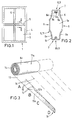
- Nachfolgend ist die Erfindung anhand der Zeichnungen näher erläutert; es zeigen:
- Fig. 1
- schematisch ein Fester mit einer Isolierverglasung in Vorderansicht,
- Fig. 2
- einen Schnitt entlang der Linie II-II in Fig. 1 in vergrößerter Darstellung,
- Fig. 3
- schematisch die Herstellung des Sprossenhohlprofils aus einem Breitbandcoil in perspektivischer Darstellung,
- Fig. 4
- einen Ausschnitt aus der erfindungsgemäßen Sprossenkreuzkonstruktion mit rechtwinklig und schräg angesetzten Querstreben,
- Fig. 5
- eine seitliche Ansicht der Sprossenkreuzkonstruktion von Fig. 1,
- Fig. 6
- die einzelnen Elemente der Konstruktion von Fig. 4 vor deren Verbindung,
- Fig. 7
- eine Schnittansicht einer Hauptstrebe mit eingestecktem Vierkantstift und einer anzusetzenden Querstrebe mit Klemmstück,
- Fig. 8
- ein bevorzugtes Ausführungsbeispiel des erfindungsgemäßen Klemmstücks,
- Fig. 9
- das Klemmstück von Fig. 8 im Querschnitt,
- Fig. 10
- ein weiteres Ausführungsbeispiel der einzelnen Elemente der Konstruktion aus Fig. 4 vor der Verbindung in derselben Darstellung wie in Fig. 6, und
- Fig. 11
- eine Schnittansicht entsprechend Fig. 7 unter Verwendung des Klemmstücks gemäß Fig. 10.
- In der Fig. 1 ist ein Fenster 1 mit Isolierverglasung und dazwischen angeordneter Sprossenkreuzkonstruktion für Sprossenfenster dargestellt. Die Erfindung betrifft jedoch nicht nur Sprossenkreuzkonstruktionen für Sprossenfenster mit einer Isolierverglasung, sondern auch Sprossenkreuzkonstruktionen für Isolierverglasungen schlechthin.
- Ein Fenster 1 mit einer Isolierverglasung weist im allgemeinen einen Fensterrahmen 2, wenigstens zwei auf Abstand angeordnete, im Fensterrahmen 2 gelagerte Glasscheiben 3 und einen die Glasscheiben 3 auf Abstand haltenden, mit Trockenmittel gefüllten Abstandhalterrahmen 4 auf. Im Zwischenraum zwischen den Glasscheiben 3 sind Sprossen bzw. Streben 5 angeordnet. Die Sprossen 5 bestehen aus Hohlprofilstangen aus Metall mit einer Längsschweißnaht 12a, die zu einem Kreuzungsgebilde zusammengesetzt sind. An den Kreuzungsstellen sind die Sprossen 5 in an sich bekannter Weise mit Kreuzverbindungsstücken zusammengesetzt (nicht dargestellt). Verbindungsstopfen übernehmen in an sich bekannter Weise die Lagerung der Sprossen 5 am Abstandhalterrahmen 4.
- Sprossen 5 können unterschiedliche Hohlprofilquerschnittsformen aufweisen. Dargestellt ist ein gängiges Profil, das parallel zu den Glasscheiben 3 angeordnete Seitenwandungen 6 und quer zu den Seitenwandungen 6 verlaufende Stirnwandungen 7 aufweist. Die Stirnwandungen 7 sind schmaler als die Seitenwandungen 6, weshalb ein vorzugsweise hohlkehlenförmiger Übergangsbereich 6a zwischen den Wandungen 6 und 7 vorgesehen ist.
- Wesentlich ist, daß in beiden Stirnwandungen 7, zweckmäßigerweise in deren Längsmitte, eine längsverlaufende Profileinziehung 8, 8b bzw. rillenförmige Einbuchtungen, 9, 9a einprofiliert ist.
- Die Profileinziehungen 8, 8b sind gleichgeformt und spiegelbildlich zueinander angeordnet. Die Tiefe jeder Rille 9, 9a beträgt z. B. 1/8 bis 1/10 der Höhe des Profils (Abstand zwischen den Stirnwandungen 7). Die Breite der Rille 9, 9a soll möglichst gering sein, jedoch in jedem Fall so gering, daß der Rillenboden von außen unsichtbar bleibt. Vorzugsweise liegen die Seitenwandungen 8a der Rillen 9, 9a aneinander.
- Die Sprossen bzw. Streben 5 werden jeweils in der erforderlichen Länge von Hohlprofilstangen 11 abgelängt. Die Hohlprofilstangen 11 sind aus einem relativ dünnen Metallband, z. B. aus Aluminium geformt, wobei die Längskanten 12 des Metallbandes aufeinanderzu gebogen werden, so daß ein geschlossenes Rohr 11a geformt wird. Die Stoßkanten bzw. Längskanten 12 werden miteinander verschweißt, so daß eine Schweißnaht 12a entsteht. Die sich anschließende Profilierung erzeugt die Rillung 9, 9a derart, daß die Schweißnaht 12a in den Innenraum 5a des Profils verdrängt und unsichtbar wird. Damit die Sprosse 5 gleichförmig aussieht, ist nach einer zweckmäßigen Ausführungsform der Erfindung vorgesehen, daß der der Rille 9 mit der Schweißnaht 12 gegenüberliegende Bereich des Rohres 11a in gleicher Weise gerillt wird und die Rillung 9a enthält.
- Die Sprosse 5 besteht - wie bereits erwähnt - vorzugsweise aus Aluminium. Die Wandstärke der Sprosse beträgt insbesondere etwa 0,4 bis 0,6 mm. Die Außenmantelfläche der Sprosse trägt vorzugsweise eine Farbschicht 6c oder ist eloxiert.
- Ein besonders einfaches Verfahren zur Herstellung einer Hohlprofilstange 11 ergibt sich aus Fig. 3. Ausgangsmaterial ist ein relativ breites Metallband 13, das von einem Breitbandcoil 14 abgezogen wird. Das Metallband 13 besteht z. B. aus Aluminium und trägt auf der Außenseite 13a eine relativ dünne Farbschicht 6c.
- Das Metallband 13 wird während des Abziehens zunächst in mehrere Streifen 15 längsgeschnitten, aus denen vorzugsweise jeweils gleichzeitig Hohlprofilstangen 11 z. B. durch Rollverformung und/oder Prägung geformt werden. Die Streifen 15 können aber auch aufgerollt und später weiterverarbeitet werden. Die Hohlprofile 11, die aus den Streifen 15 geformt werden, können gleiche oder unterschiedliche Querschnittsformen aufweisen. Ebenso können die Streifen 15 gleich breit oder unterschiedlich breit sein.
- Die Aufteilung des Metallbandes 13 in mehrere Streifen 15 durch längsverlaufende Einschnitte 16 erfolgt an einer Bearbeitungsstation A, die das Metallband 13 beim Abziehen durchläuft. In Abzugsrichtung befindet sich hinter der Bearbeitungsstation A eine Bearbeitungsstation B mit Formgebungswerkzeugen (nicht dargestellt), in denen der Streifen 15 zu einem z. B. im Querschnitt kreisrunden Rohr 11a mit aneinanderstoßenden Längskanten 12 geformt wird. Die Farbschicht 6c befindet sich dabei auf der Außenmantelfäche des Rohres. An einer der Bearbeitungsstation B nachgeordneten Bearbeitungsstation C mit einer Schweißvorrichtung werden die Längskanten 12 zur Schweißnaht 12a verschweißt, vorzugsweise laserverschweißt. Hinter der Bearbeitungsstation C befindet sich eine Bearbeitungsstation D mit Formwerkzeugen (nicht dargestellt), mit denen die Profileinziehungen 8, 8b eingeformt werden und gleichzeitig oder nachfolgend auch die Profilierungen der Seitenwandungen 6, 6a und Stirnwandungen 7 geformt werden können.
- Beim Schweißen verbrennt im Bereich der Schweißnaht 12a Farbe. Durch die erfindungsgemäße Profileinziehung im Bereich der Schweißnaht werden die Schweißnaht selbst sowie die durch die Hitze beim Schweißen beeinträchtigten Farbbereiche in der Rille 9 versteckt, so daß sie von außen unsichtbar bleiben. Durch diese ungewöhnliche Maßnahme wird erreicht, daß aus einem beschichteten Metallband geformte und geschweißte Hohlprofile als Sprossen verwendet werden können, ohne daß die Schweißnaht und die zum Teil verbrannten Farbbereiche optisch stören. Aber auch bei Verwendung unbeschichteter Metallbänder können Sprossen geformt werden, deren Schweißnaht versteckt ist und nicht optisch störend wirkt.
- Die kontinuierlich hergestellten Hohlprofilstangen 11 werden auf geeignete Handelslängen abgelängt und stehen als Zwischenprodukt dem Hersteller von Isolierverglasungen zur Verfügung. Der Hersteller längt die Sprossen 5 von der Hohlprofilstange 11 ab und bildet die gewünschten Sprossenkonfigurationen für eine Isolierverglasung.
- Aus vorstehendem folgt hinsichtlich des Herstellungsverfahrens, zumindest eine Profileinziehung zur Unsichtbarmachung einer Schweißnaht vorzusehen und schlägt aus optischen Gründen vor, zumindest eine weitere Profileinziehung spiegelbildlich zur Profileinziehung mit der Schweißnahnt anzuordnen. Dabei muß die Schweißnaht nicht an einer Stirnseite angeordnet sein. Sie kann vielmehr z. B. auch an einer Seitenwandung liegen, wenn die optischen Anforderungen an das Sprossenprofil dies zulassen.
- Die Fig. 4 zeigt ein Ausführungsbeispiel einer Sprossenkreuzkonstruktion, die ein als Hauptstrebe oder -sprosse dienendes Hohlprofil 101 aus Metallblech, zwei senkrecht angesetzte Hohlprofil-Querstreben 102 und eine schräg angesetzte Hohlprofil-Querstrebe 103 umfaßt. Die Streben 101, 102 und 103 sind im Rollverfahren hergestellt und identisch ausgebildet. Die Rollung des Blech-Ausgangsmaterials, aus dem die Profile bestehen, ist so vorgenommen, daß an beiden Profillängsseiten eine innenliegende Sicke oder Falte 104 ausgebildet ist, die zur Stabilität der Profile beiträgt. Die spezielle Querschnittsform der Streben 101, 102 und 103 ist beispielsweise aus der Fig. 5 ersichtlich, die eine seitliche Ansicht der in Fig. 4 linken Hälfte der Sprossenkonstruktion zeigt, und zwar eine Ansicht auf die in Fig. 4 links gelegene Schmalseite der beiden Querstreben 102, die ebenso wie die Querstrebe 103 an ihren Anschlußenden durch Konturfräsung so abgeschnitten sind, daß sich ein oberer und unterer Abschnitt 105 bzw. 105' ergeben, die die Hauptstrebe 101 seitlich überlappend umgreifen. Durch die in Fig. 5 gewählte Darstellung ergibt sich eine Ansicht der Hauptstrebe 101, die einem Profilquerschnitt entspricht. Dabei sind die beiden seitlichen Sicken 104 sichtbar, die in einer zur Zeichnungsebene senkrecht verlaufenden Ebene angeordnet sind, welche eine der beiden Spiegelsymmetrieebenen der Streben 101, 102 und 103 darstellt. Die zweite Spiegelsymmetrieebene verläuft senkrecht zu der erstgenannten durch die beiden Profilbreitseiten. Die Profilbreitseiten umfassen zwei parallel zueinander verlaufende Kopfflächen 106 und 106' sowie zwei sich seitlich an diese anschließende zu den Profilschmalseiten hin abfallende Schrägflächen 107 und 107', die konkav gewölbt sind. Die Kontur der Profilschmalseiten ergibt sich durch die interne Sickenausbildung als abgerundeter Übergang 108 und 108' von den Schrägflächen 107 bzw. 107' zu den Sicken 104 und 104'.
- Die Konturfräsung an den Anschlußenden der Querstreben 102 und der Querstrebe 103 ist derart gewählt, daß ein vorstehender Teil 109 und 109' der Kopffläche dieser Streben bei an die Hauptstrebe angesetzter Querstrebe an die Übergangskante dessen Kopffläche 106 bzw. 106' zu der sich anschließenden Schrägfläche 107 bzw. 107' anstößt. Die Vorderkante des vorspringenden Teils 109 bzw. 109' verläuft demnach gerade, und zwar senkrecht zur Längsachse der Strebe. An dem vorstehenden Teil 109 bzw. 109' schließen sich seitliche, zurückweichende Kanten 110 an, die bei an die Hauptstrebe 101 angesetzten Querstreben mit ihren Schnittkanten an die konvex verlaufenden Schrägflächen 107 und 107' angrenzen. Die schrägverlaufenden Kanten 110 erstrecken sich an den Querstreben-Anschlußenden bis zu deren Schmalseiten, die gerade verlaufend derart beschnitten sind, daß sie an die Schmalseiten der Hauptstrebe 101 anstoßen.
- Damit ergibt sich im Bereich der Anschlußenden der Querstreben-Profile bei Aufsicht auf deren Schmalseiten ein im wesentlichen U-förmiger Profilverlauf, wobei die U-Schenkel der Konturfräsung entsprechend gebogen verlaufen. Bei Aufsicht auf die Breitseiten der Querstreben ergibt sich im Bereich deren Anschlußenden im wesentlichen ein trapezförmiger Profilverlauf.
- Die vorstehend beschriebene Gestalt der Hohlprofil-Streben soll einen bei realen Sprossen vorliegenden optischen Eindruck vermitteln. Diese Gestalt ist jedoch nicht zwingend. Vielmehr können alle möglichen, im wesentlichen rechtwinkligen Querschnittsformen zur Anwendung gelangen.
- Wesentlich an der in Rede stehenden Sprossenkreuzkonstruktion ist es, daß ein Skelettaufbau gewählt ist, der es gestattet, die Wandstärke der Hohlprofil-Streben entscheidend geringer zu gestalten als bei herkömmlichen Hohlprofil-Streben, die für Sprossenkreuzkonstruktionen verwendet werden. Insbesondere gestattet es der nachfolgend näher beschriebene Skelettaufbau, daß Profile mit einer bis zu 10 Mal geringeren Wandstärke als bei bisherigen Sprossenkreuzkonstruktionen verwendet werden können.
- Ein Element des Skelettaufbaus ist in den Fig. 4 und 5 dargestellt, nämlich ein Verbindungsstift 111. Der Verbindungsstift 111 durchsetzt die Hauptstrebe 101 in Querrichtung, deren Schmalseitenwandungen mit Durchstecköffnungen 112 versehen sind, wie beispielsweise aus Fig. 6 hervorgeht, die eine Explosionsansicht der Elemente der Sprossenkreuzkonstruktion von Fig. 4 zeigt, wobei die Verbindungsstifte 111 in als Klemmstücke ausgebildete Klemmstücke 113 eingesetzt sind, die auf nachfolgend näher beschriebene Weise in die Anschlußenden der Querstreben eingesetzt sind.
- Wie aus den Fig. 6 bis 9 hervorgeht, ist das Klemmstück als Vollkörper ausgebildet, dessen Kontur, wie am besten aus der Querschnittsdarstellung von Fig. 3 hervorgeht, an die Innenwandungskontur der Profile angepaßt ist. So finden sich bei den Klemmstücken 113 in komplementärer Ausbildung zu den Hohlprofilen zwei flach verlaufende, einander gegenüberliegende Kopfflächen 114 und 114' sowie sich seitlich an diese anschließende Schrägflächen 115 und 115', die den Schrägflächen 107 der Hohlprofile entsprechend konvex gekrümmt sind. Die Seitenflächen 116 sind bei dem dargestellten Ausführungsbeispiel gemäß Fig. 3 lediglich grob an die Innenkontur der Hohlprofile angepaßt, die an diesen Stellen die Sicken 107 und 107' und die Rundungsflächen 108 und 108' aufweisen, die im Querschnitt zusammen mit den zentralen Sicken einen Verlauf aufweisen, der an den bauchigen Verlauf eines B erinnert. Die Seitenflächen 116 weisen diese Konturfeinheit nicht auf, weshalb die Breitenausdehnung des Klemmstücks 113 von Seitenfläche 116 zu Seitenfläche 116 in etwa dem lichten Abstand zwischen den einander gegenüberliegenden Sicken 104 in den Hohlprofilen entspricht. Alternativ hierzu kann es vorteilhafterweise vorgesehen sein, die genannte Breitenausdehnung des Klemmstücks 113 so groß zu wählen, daß sie dem Abstand der Schmalseiteninnenwände der Hohlprofile entspricht. In diesem Falle sind in den Seitenwänden 116 des Klemmstücks 113 an den Stellen Ausnehmungen vorgesehen, die an die Sicken 104 angrenzen. Hierdurch wird ein allseitiger Flächenkontakt des Klemmstücks 113 mit der Innenwandung des jeweiligen Hohlprofils erreicht.
- Wie aus den Querschnittsdarstellungen des Klemmstücks 113 von Fig. 9 hervorgeht, ist im Klemmstückzentrum eine Bohrung bzw. ein Loch 117 ausgebildet, die zur Aufnahme des Verbindungsstifts 111 dient und eine Querschnittsgestalt aufweist, die an diejenige des Verbindungsstifts paßgenau angeglichen ist. Bevorzugt ist die in Fig. 9 dargestellte Querschnittsform, nämlich ein quadratischer Querschnitt der Bohrung 117 sowie ein entsprechender quadratischer Querschnitt des Verbindungsstifts 111.
- Um einen festen Sitz des Verbindungsstifts 111 in der Stiftaufnahmebohrung 117 des Klemmstücks 113 zu gewähleisten, sowie gleichzeitig einen festen Sitz des Klemmstücks 111 im Anschlußendabschnitt der Querstreben, ist das Klemmstück 113, wie am besten aus Fig. 8 hervorgeht, in Art eines Kunststoffdübels gespreizt ausgebildet. Zu diesem Zweck ist das Vollkörper-Klemmstück 113 in Längsrichtung mit einem Schlitz 118 versehen, der sich in Richtung der Mittellängsachse des Klemmstücks 113 erstreckt. Die Basis des Schlitzes 118 liegt im vorderen Drittel der Paßbohrung 117 für den Stift 111, welche Bohrung sich ebenfalls entlang der Längsmittenachse des Klemmstücks 113 erstreckt, und zwar mit einer Längserstreckung, die in etwa zwei Dritteln der Länge des Klemmstücks 113 entspricht. Mit anderen Worten ist die Paßbohrung 117 als Sackloch ausgebildet. Ausgehend von seiner Basis im in Stifteinstreckrichtung vorderen Teil der Paßbohrung 117 öffnet sich der Schlitz zum gegenüberliegenden Ende des Klemmstücks 113 hin mit einem in der Zeichnungsebene gelegenen Winkel α, wie aus der linken Hälfte der Fig. 8 hervorgeht. Die rechte Hälfte der Fig. 8 zeigt den in eine Querstrebe vollständig eingesetzten Zustand des Klemmstücks 113, das zur besseren Übersichtlichkeit ebensowenig dargestellt ist, wie der in die Paßbohrung 117 eingesetzte Stift 111. Dabei wird deutlich, daß die in der entspannten Spreizstellung gemäß der linken Hälfte von Fig. 8 gerade verlaufende Paßbohrung 117 im zusammengepreßten Zustand des Klemmstücks 113 gemäß der rechten Hälfte der Fig. 8 im Bereich des Schlitzes 118, dessen V-förmige Spreizung vollständig überwunden ist, einen in Einsteckrichung des Stiftes 111 sich zunehmend verringernden Querschnitt aufweist. Dies hat bei eingestecktem Stift die Wirkung, daß die potentielle Spreizkraft des Klemmstücks im eingesetzten Zustand unterstützt wird durch die quer zur Stifteinsteckrichtung auf die Paßbohrung 117 im Schlitzbereich durch den Schlitz auf die Bohrungswände ausgeübte Spreizkraft, die durch eine Verdichtung des Klemmstückmaterials im Schlitzbereich der Paßbohrung bewirkt wird. Die Folge hiervon ist ein exzellenter Preßsitz des Klemmstücks 113 in dem jeweiligen Hohlprofil sowie ein ebenso hochwertiger Preßsitz des Stiftes 111 in der Paßbohrung 117.
- Wie aus der Fig. 8 weiterhin hervorgeht, ist das Klemmstück 113 an seinem in seiner Einsteckrichtung vorderen Ende unter einem Winkel β verjüngt ausgebildet. Zu diesem Zweck weist es schräg verlaufende Seitenwandteile 120 auf. Diese sind vorzugsweise sowohl an den Seitenwänden 116 wie an den Kopfflächen 114 und gegebenenfalls auch an den Schrägflächen 115 ausgebildet. Diese keilförmige Ausbildung des vorderen Klemmstücks erlaubt insbesondere angesichts der gespreizten Ausbildung des Klemmstücks ein vereinfachtes Einsetzen in das Anschlußende der jeweiligen Querstrebe.
- Im Bereich seiner in Einsteckrichtung hinteren Stirnfläche 121 ist das Klemmstück 113 verbreitert ausgebildet, und zwar ebenfalls durch Schrägflächen, nämlich durch die Flächen 120, die im Verlauf komplementär zu den Schrägflächen 120 angelegt sind. Dadurch wird ein besonders inniger Preßkontakt des Klemmstücks 113 an seinem außen gelegenen Ende erreicht. Zwischen den Schrägflächen 122 am hinteren und den Schrägflächen 120 am vorderen Ende des Klemmstücks 113 erstrecken sich ebenfalls schräg verlaufende Wandteile 123 im Bereich der Seitenwände 116. Diese verlaufen unter einem Winkel γ, der halb so groß ist wie der Öffnungswinkel α des Schlitzes 118, und diese Wandteile 123 nehmen bei in ein Querhohlprofil eingesetztem Klemmstück 113 eine parallele Ausrichtung zu den Profilseitenwänden ein, analog zu einem Kunststoffspreizdübel.
- Die in Fig. 6 gezeigte Variante des Klemmstücks 113 entspricht der Ausführung des Klemmstücks von Fig. 8 mit dem Unterschied, daß die vorne gelegenen Schrägwände 122 bei der Variante von Fig. 6 nicht vorgesehen sind, sowie mit dem Unterschied, daß sich der Längsschlitz 118 bis nahe an die stifteinsteckseitige Stirnwand des Klemmstücks 113 erstreckt. Dargestellt ist das Klemmstück 113 in Fig. 6 in dem Zustand, den es einnimmt, wenn es in das Hohlprofil 102 eingesteckt ist, also nach Überwindung der ursprünglichen aufgespreizten Gestalt des Klemmstücks 113, wie sie in der linken Hälfte von Fig. 8 dargestellt ist. Links und rechts zum Schlitz 118 verlaufen parallel zu diesem in den Kopfflächen 114 und 114' des Klemmstücks 113 Nuten 124, die sich über die gesamte Länge des Klemmstücks 113 erstrecken und in die jeweiligen Stirnflächen einmünden. Durch diese Nuten wird eine gewisse Elastizität des Klemmstücks 113 in Querichtung, also in Richtung auf seine beiden Schmalseiten 116 hin bewirkt, die die Einschiebbarkeit des Klemmstücks in das jeweilige Hohlprofil erleichtert.
- Wie aus Fig. 7 in Verbindung mit Fig. 5 hervorgeht, schließt die vordere Stirnfläche des Klemmstücks 113 bündig mit den Kanten der zurückgesetzten Schmalseiten der Querstreben ab. Dies ist die Basis des U-förmigen Profilquerschnitts bei Aufsicht auf die Schmalseite des Profilanschlußendes. Dadurch wird eine großflächige Auflage der vorderen Klemmstück-Stirnfläche an der gegenüber gelegenen Schmalseite des Haupthohlprofils erreicht. Aus Fig. 7 geht ferner hervor, daß die Länge des Verbindungsstiftes 111 und die Tiefe der Paßbohrungen 117 so gewählt sind, daß Stift und Klemmstücke bei vollständig in die Klemmstücke eingesetztem Stift ein starres und hochsteifes Skelett bilden, ohne daß die Hohlprofile 101 und 102 ebenfalls eine Paßverbindung eingehen. Es ist vielmehr so, daß die Querhohlstreben 102 bei einer vollständigen Verbindung der Skelettelemente 111 und 113 zwar die Hauptstrebe 101 optisch einwandfrei überlappen, eine Kraftausübung der Hohlprofilteile aufeinander jedoch nicht stattfindet. Die Hohlprofile bilden vielmehr gewissermaßen eine als Verblendung der Skelettkonstruktion dienende Haut, die keinerlei Verbiegungskräften ausgesetzt ist. Aus diesem Grunde können die Hohlprofile der vorstehend beschriebenen Sprossenkonstruktion wesentlich dünner ausgebildet sein als beim Stand der Technik, bei dem den Hohlprofilen eine tragende Funktion zukommt.
- Aus der Fig. 7, aber auch aus dem mittleren Teil der Fig. 6 geht hervor, daß die Durchstecklöcher 112 in der Hauptstrebe 101 in der Zeichnungsebene, dies ist die Kreuzsprossenebene, eine Abmessung aufweisen, die in etwa der Stärke des Verbindungsstiftes 111 in dieser Ebene entspricht. Dadurch wird eine spielfreie Aufnahme der Stifte 111 in der Kreuzsprossenebene erreicht, was zur Folge hat, daß der vorbestimmte Kreuzwinkel genau eingehalten wird. Senkrecht zur Kreuzsprossenebene ist der Stift 111 hingegen in den Durchsteckoöffnungen 112 mit Spiel aufgenommen. Dies wird dadurch erreicht, daß sich die Durchstecköffnungen im wesentlichen bis an die Kopfflächen 106 und 106' des Haupthohlprofils sowie über die gesamte Breite der Schmalseiten des Haupthohlprofils erstrecken. Dadurch ergibt sich folgende Gestalt der Durchstecköffnungen 112. Bei Betrachtung auf die Schmalseiten der Hauptstrebe 101 weisen die Durchstecklöcher eine rechteckige Gestalt auf, wobei die Schmalseiten des Rechtecks in Längsrichtung der Hauptstrebe 101 verlaufen und der Stärke des Stifts 111 entsprechen, während die lange Seite dieses Rechtecks die Stärke des Stifts übertrifft; bei einer Betrachtung auf die Breitseiten der Hauptstreben 101 verlaufen die Durchstecköffnungen 112 für den Stift 111 U-förmig, und die Basis dieser U-förmigen Gestalt ist um einen vorbestimmten Betrag von der Außenkante der Hohlstrebe zurückgesetzt, und zwar vorzugsweise bis hin zur Kopfseite 106 der Hohlstrebe 101 oder doch zumindest bis in die Mitte der jeweiligen Schrägfläche 107 hinein. Auf keinen Fall erstreckt sich die Basis der U-Form soweit in die Hauptstrebe hinein, daß dessen Struktur geschwächt wird, oder daß keine Abdeckung durch den Vorsprung 105 der voll angesetzten Querstreben 102 erfolgt.
- Die Fig. 10 und 11 zeigen ein abgewandeltes Ausführungsbeispiel der Sprossenkreuzkonstruktion in derselben Ansicht und Anordnung wie die Sprossenkreuzkonstruktion gemäß den Fig. 6 und 7, wobei lediglich auf die Unterschiede gegenüber der Anordnung gemäß den Fig. 6 und 7 eingegangen wird.
- Der Hauptunterschied der Sprossenkreuzkonstruktion gemäß den Fig. 10 und 11 im Vergleich zu der vorstehend beschriebenen Sprossenkreuzkonstruktion besteht in einer abweichenden Gestalt der Klemmstücke 113. So ist das Klemmstück 113 gemäß den Fig. 6 und 7 nicht mit einem Längsschlitz versehen und weist eine Kontur mit einem vorne gelegen Vorsprung auf, wie nachfolgend näher beschrieben werden soll.
- Wie aus Fig. 10 und 11 ersichtlich ist, sind die Klemmstücke 113 so geformt, daß sie sich mit mehreren, insgesamt vier Paßflächen in das Ende der gerade oder schräg angesetzten Querstrebe oben, unten und seitlich einpassen. Die oberen und unteren Paßflächen 125 sind durch zwei Nuten unterteilt und über die an die Hauptstrebe 101 anzusetzende Stirnseite des Klemmstücks 113 hinweg zu einem vorstehenden Endabschnitt 126 verlängert, der wegen der Unterteilung aus drei Einzelsegmenten besteht, die sich bei dem Anschluß an die Hauptstrebe 101 ähnlich wie die Überlappungsabschnitte 105 flächig auf die Hauptstrebe 101 legen. Durch die Segmentierung ist es möglich, auch bei weniger elastischen Kunststoffen und einer größeren Wandstärke der Segmente deren federnde Anlage mit Preßsitzwirkung an die seitliche Ober- und Unterseite der Hauptstreben zu erzielen.
- Die Abschnitte 126 sind etwas kürzer ausgebildet als die Überlappungsabschnitte 105 der Querstreben 102 und 103, so daß sie nach Verbindung der Profilteile nicht sichtbar sind. Die aus Kunststoff, zum Beispiel im Spritzgießverfahren gefertigten Klemmstücke 113 nehmen die Stifte 111 in exakt ausgeführten Vierkantausnehmungen, wie vorstehend bereits beschrieben, mit Preßsitz auf.
- Um eine noch bessere formschlüssige Anpassung der Klemmstücke 113 zu erzielen, sind an deren Seitenflächen nicht nur Nuten zur Aufnahme der Sicken 104 ausgenommen, sondern parallel zu den Klemmstück-Kopfseiten ist ein Grat ausgebildet, der sich in die in Fig. 5 sichtbare, durch die Sicke 104 gebildete Vertiefung an der Außenseite der Hauptstrebe 101 einfügt.
- Vorzugsweise sind ferner zur festeren Einpassung der Klemmstücke 113 auf den Kopfseiten 114 und 114' und Seitenwänden in Einstreckrichtung verlaufende Reibrippen ausgebildet. Hierdurch sind sowohl die Anforderungen an die Präzision für die Fertigung und Bearbeitung der Hohlprofile wie auch der Klemmstücke verringert.
- Die Form der Haupt- und Querstreben und die Einpassung der daran angepaßten Klemmstücke ist nicht auf die dargestellte Lösung beschränkt, vielmehr kann je nach Anforderung hiervon auch beträchtlich abgewichen werden und auch andere Arten der Einpassung gewählt werden. So ist es prinzipiell möglich, die Form der Klemmstücke nur sehr grob derjenigen der Querstreben anzupassen und zur festen Einpassung ersterer eine aushärtende Kunststoffmasse zu verwenden. Das gleicht gilt für den Einsatz des oder der Stifte in die Klemmstücke. Zur Formung der Kunststoff-Klemmstücke werden vorzugsweise Form- oder Konturfräser eingesetzt.
- Dies gilt auch für die Herstellung der Abschnitte 104, 104' der Hohlprofile. Die Länge der Klemmstücke 113 richtet sich sowohl nach der Breite als auch Wandstärke der Querstreben 102 und 103. Dies gilt auch für die Länge der Überlappungsabschnitte 126. Abhängig von der Größe und Wandstärke der Querstreben, der Einpassung und dem Material der Klemmstücke sind unterschiedlichste Dimensionierungen mit der vorteilhaften Übertragung der Verbindungskräfte der Sprossenkreuzkonstruktion auf das Klemmstück-Stift-Skelett möglich.
Claims (11)
- Verbindungsvorrichtung für eine Sprossenkreuzkonstruktion mit Hauptstreben (101) und Querstreben (102 oder 103) aus gleichen, zwei Breitseitenwandungen und zwei Schmalseitenwandungen aufweisenden Hohlprofilen, wobei
mit einer Hauptstrebe (101) zwei seitlich angrenzende Querstreben (102 oder 103) verbunden sind,
als Verbindungsmittel jede Schmalseitenwandung der Hauptstrebe (101) ein Durchsteckloch aufweist,
die Durchstecklöcher (112) von einem beidseits aus der Hauptstrebe (101) herausragenden Stift (111) durchgriffen sind,
die Enden des Stiftes (111) jeweils in einem Loch (117) eines Klemmstücks (113) stecken,
die Klemmstücke (113) der Innenkontur der Querstreben (102 oder 103) angepaßt sind und jeweils mit Preßsitz im Endbereich einer Querstrebe (102 oder 103) sitzen,
dadurch gekennzeichnet,
daß das Loch (117) im Klemmstück (113) als in Stifteinsteckrichtung konisch verjüngtes Loch derart ausgebildet ist, daß das Klemmstück (113) beim Einführen des Stifts (111) in das Loch (117) quer zum Loch aufgeweitet und dadurch gegen die Innenwandung der Querstrebe (102 oder 103) verkeilt wird und im Bereich der hinteren Stirnkante des Klemmstücks (113) beide Schmalseitenwandungen des Klemmstücks nach seitlich außen verbreitert sind (bei 122) und dadurch ein Stoppmittel festlegen, durch das ein Versetzen des Klemmstücks (113) in die Querstrebe (102 oder 103) hinein verhindert wird, wenn der Stift (111) in das konisch verjüngte Loch des Klemmstücks (117) eingeführt wird. - Verbindungsvorrichtung nach Anspruch 1,
dadurch gekennzeichnet,
daß das Klemmstück (113) in Art eines Spreizdübels längsgeschlitzt ausgebildet ist, wobei der Schlitz (118) in die Einsteckrichtung vordere Stirnkante des Klemmstücks (113) mündet, das Stiftaufnahmeloch (117) durchsetzt, vor der hinteren Stirnkante des Klemmstücks (113) endet und bei entspanntem, nicht in die Querstrebe (102 oder 103) eingesetztem Klemmstück (113) Keilform so aufweist, daß zwei durch den Schlitz (118) festgelegte Klemmstück-Schenkel mit jeweils zueinander parallelen Seitenlängskanten in Richtung auf die vordere Klemmstück-Stirnkante hin auseinander laufen, wobei die beiden Schenkel bei in die Querstrebe eingesetztem Klemmstück (117) untere Keilwirkung aufgrund des geschlossenen Schlitzes (118) quer zu diesem gegen die Schmalseiteninnenwandung der Querstrebe (102 oder 103) verspannt sind. - Verbindungsvorrichtung nach Anspruch 1 oder 2,
dadurch gekennzeichnet,
daß das Stiftaufnahmeloch (117) im Klemmstück (113) ein Sackloch ist. - Verbindungsvorrichtung nach einem oder mehreren der Ansprüche 1 bis 3,
dadurch gekennzeichnet,
daß das Stiftaufnahmeloch (117) im Klemmstück (113) eine Paßbohrung für den Stift (111) ist. - Verbindungsvorrichtung nach einem oder mehreren der Ansprüche 1 bis 4,
dadurch gekennzeichnet,
daß der Stift (111) und das Stiftaufnahmeloch (117) vierkantigen Querschnitt aufweisen. - Verbindungsvorrichtung nach Anspruch 5,
dadurch gekennzeichnet,
daß die Klemmstücke (113) im Bereich ihrer vorderen Stirnkanten unter Festlegung schräg verlaufender Führungsflächen (112) verjüngt ausgebildet sind. - Verbindungsvorrichtung nach einem oder mehreren der Ansprüche 1 bis 6,
dadurch gekennzeichnet,
daß das Stoppmittel im Bereich der hinteren Stirnkante der Klemmstücke (113) durch einen über die Außenkontur des Klemmstücks überstehenden Rand (122) festgelegt sind. - Verbindungsvorrichtung nach Anspruch 7,
dadurch gekennzeichnet,
daß der Rand durch schräg zur hinteren Stirnkante ansteigende Schrägflächen (122) der Klemmstück-Außenwandung gebildet ist. - Verbindungsvorrichtung nach einem oder mehreren der Ansprüche 1 bis 8,
dadurch gekennzeichnet,
daß der Stift (111) über seine gesamte Länge gleich stark ausgebildet ist. - Verbindungsvorrichtung nach einem oder mehreren der Ansprüche 1 bis 9,
dadurch gekennzeichnet,
daß sich das Stiftaufnahmeloch (117) in den Klemmstücken (113) in etwa über zwei Drittel der Länge der Klemmstücke (113) erstreckt. - Verbindungsvorrichtung nach einem oder mehreren der Ansprüche 1 bis 10,
dadurch gekennzeichnet,
daß sich der Schlitz (118) in den Klemmstücken (113) in etwa über zwei Drittel der Länge der Klemsmtücke (113) erstreckt.
Priority Applications (2)
| Application Number | Priority Date | Filing Date | Title |
|---|---|---|---|
| EP97111659A EP0801202B1 (de) | 1990-09-25 | 1991-08-10 | Verbindungsvorrichtung für eine Sprossenkreuzkonstuktion |
| GR970300064T GR970300064T1 (en) | 1990-09-25 | 1998-01-30 | Lattice cross assembly device |
Applications Claiming Priority (7)
| Application Number | Priority Date | Filing Date | Title |
|---|---|---|---|
| DE4030335 | 1990-09-25 | ||
| DE4030335A DE4030335C2 (de) | 1990-09-25 | 1990-09-25 | Sprossenhohlprofil für Isolierverglasungen sowie Verfahren zu seiner Herstellung |
| DE4041161 | 1990-12-21 | ||
| DE19904041161 DE4041161C2 (de) | 1990-12-21 | 1990-12-21 | Verbindungsvorrichtung für eine Sprossenkonstruktion und Verfahren zur Herstellung einer Sprossenkonstruktion mit dieser Verbindungsvorrichtung |
| DE9102189U DE9102189U1 (de) | 1990-12-21 | 1991-02-25 | Verbindungsvorrichtung für eine Sprossenkonstruktion |
| DE9102189U | 1991-02-25 | ||
| EP91113443A EP0477513B1 (de) | 1990-09-25 | 1991-08-10 | Verbindungsvorrichtung für eine Sprossenkreuzkonstruktion |
Related Parent Applications (2)
| Application Number | Title | Priority Date | Filing Date |
|---|---|---|---|
| EP91113443.5 Division | 1991-08-10 | ||
| EP91113443A Division EP0477513B1 (de) | 1990-09-25 | 1991-08-10 | Verbindungsvorrichtung für eine Sprossenkreuzkonstruktion |
Related Child Applications (1)
| Application Number | Title | Priority Date | Filing Date |
|---|---|---|---|
| EP97111659A Division EP0801202B1 (de) | 1990-09-25 | 1991-08-10 | Verbindungsvorrichtung für eine Sprossenkreuzkonstuktion |
Publications (2)
| Publication Number | Publication Date |
|---|---|
| EP0578268A1 true EP0578268A1 (de) | 1994-01-12 |
| EP0578268B1 EP0578268B1 (de) | 1998-01-21 |
Family
ID=27201718
Family Applications (5)
| Application Number | Title | Priority Date | Filing Date |
|---|---|---|---|
| EP93112155A Expired - Lifetime EP0578268B1 (de) | 1990-09-25 | 1991-08-10 | Verbindungsvorrichtung für eine Sprossenkreuzkonstruktion |
| EP93112168A Expired - Lifetime EP0577150B1 (de) | 1990-09-25 | 1991-08-10 | Sprossenhohlprofil aus Metall für Isolierverglasungen sowie Verfahren zu seiner Herstellung |
| EP96105101A Expired - Lifetime EP0724061B1 (de) | 1990-09-25 | 1991-08-10 | Verbindungselement |
| EP91113443A Expired - Lifetime EP0477513B1 (de) | 1990-09-25 | 1991-08-10 | Verbindungsvorrichtung für eine Sprossenkreuzkonstruktion |
| EP97111659A Expired - Lifetime EP0801202B1 (de) | 1990-09-25 | 1991-08-10 | Verbindungsvorrichtung für eine Sprossenkreuzkonstuktion |
Family Applications After (4)
| Application Number | Title | Priority Date | Filing Date |
|---|---|---|---|
| EP93112168A Expired - Lifetime EP0577150B1 (de) | 1990-09-25 | 1991-08-10 | Sprossenhohlprofil aus Metall für Isolierverglasungen sowie Verfahren zu seiner Herstellung |
| EP96105101A Expired - Lifetime EP0724061B1 (de) | 1990-09-25 | 1991-08-10 | Verbindungselement |
| EP91113443A Expired - Lifetime EP0477513B1 (de) | 1990-09-25 | 1991-08-10 | Verbindungsvorrichtung für eine Sprossenkreuzkonstruktion |
| EP97111659A Expired - Lifetime EP0801202B1 (de) | 1990-09-25 | 1991-08-10 | Verbindungsvorrichtung für eine Sprossenkreuzkonstuktion |
Country Status (15)
| Country | Link |
|---|---|
| EP (5) | EP0578268B1 (de) |
| JP (1) | JPH0687043A (de) |
| AT (5) | ATE162588T1 (de) |
| CZ (3) | CZ286034B6 (de) |
| DE (7) | DE9116882U1 (de) |
| DK (3) | DK0477513T3 (de) |
| ES (4) | ES2112934T3 (de) |
| FI (3) | FI97637C (de) |
| GR (5) | GR920300091T1 (de) |
| HU (1) | HU216266B (de) |
| NO (1) | NO300819B1 (de) |
| PL (1) | PL168382B1 (de) |
| RU (2) | RU2061168C1 (de) |
| SK (1) | SK268491A3 (de) |
| TR (2) | TR26479A (de) |
Families Citing this family (13)
| Publication number | Priority date | Publication date | Assignee | Title |
|---|---|---|---|---|
| GB2291914B (en) * | 1994-08-04 | 1997-06-11 | Equator Wheels & Sections Ltd | Joining members for window frames |
| DE29825152U1 (de) * | 1998-04-21 | 2005-08-04 | SCHÜCO International KG | Tragprofile für Riegel-Pfosten-Fassaden, Vordächer, Galerien o.dgl. |
| ES2196934B1 (es) * | 2000-10-10 | 2006-05-16 | Giesse Group Iberia, S.A. | Procedimiento de obtencion de un elemento de union para mecanismo de cierre en ventanas oscilantes y/o batientes, y elemento de union obtenido. |
| US7319561B2 (en) | 2004-12-27 | 2008-01-15 | Nippon Sheet Glass Company, Limited | Stereoimage formation apparatus and stereoimage display unit |
| DE102008050541A1 (de) | 2008-10-06 | 2010-04-08 | Helmut Lingemann Gmbh & Co | Hohlprofil, insbesondere Sprossenhohlprofil, sowie Verfahren und Vorrichtung zu seiner Herstellung |
| DE102008062333A1 (de) | 2008-12-15 | 2010-06-17 | Schott Ag | Abstandshalter mit einem expandierenden Material für Brandschutzverglasungen |
| US10578864B2 (en) | 2015-10-09 | 2020-03-03 | Maxell, Ltd. | Head-up display device |
| CN107587698A (zh) * | 2017-10-25 | 2018-01-16 | 湖州美诺玻璃有限公司 | 一种十字连接结构 |
| CN108385935A (zh) * | 2017-10-25 | 2018-08-10 | 湖州美诺玻璃有限公司 | 一种长连接件 |
| CN110159137A (zh) * | 2018-03-27 | 2019-08-23 | 利辛县缘艺纱网有限公司 | 一种纱门窗的假中梃结构 |
| JP6695062B2 (ja) | 2018-03-29 | 2020-05-20 | パナソニックIpマネジメント株式会社 | 表示システム、制御装置、制御方法、プログラム、及び移動体 |
| CN109252672A (zh) * | 2018-10-16 | 2019-01-22 | 肖霞 | 外墙阴阳角及平面保温层与非保温层处的施工处理方法 |
| KR102799025B1 (ko) * | 2021-12-06 | 2025-04-25 | 주식회사 아린엠에이치씨 | 도어 |
Citations (6)
| Publication number | Priority date | Publication date | Assignee | Title |
|---|---|---|---|---|
| BE471548A (de) * | ||||
| DE8710362U1 (de) * | 1987-07-29 | 1987-12-23 | Schmitz, Werner, Dipl.-Ing., 3470 Höxter | Sprossenverbinder |
| DE3638355A1 (de) * | 1986-11-10 | 1988-05-11 | Fuehrer Andreas | Vorrichtung zur verbindung von profilkreuzen in sprossengittern |
| DE8900359U1 (de) * | 1989-01-13 | 1989-03-09 | GKT Glas- und Kunststofftechnik, 3492 Brakel | Abstandhalterahmen für Isolierverglasungen |
| DE8913616U1 (de) * | 1989-11-17 | 1990-01-04 | GKT Glas- und Kunststofftechnik, 3492 Brakel | Abstandhalterahmen für Isolierverglasungen |
| DE3941288A1 (de) * | 1988-12-27 | 1990-06-28 | Manfred Muehle | Tuer oder fenster mit im glasausschnitt angeordneten waermegedaemmten glastrennenden sprossen |
Family Cites Families (7)
| Publication number | Priority date | Publication date | Assignee | Title |
|---|---|---|---|---|
| GB1515312A (en) * | 1974-10-21 | 1978-06-21 | Custom Rollforming | Spacer for double glazed windows |
| DE2637034C2 (de) * | 1976-08-17 | 1982-06-03 | Helmut Lingemann GmbH & Co, 5600 Wuppertal | Abstandhalterrahmen für Isolierverglasungen |
| DE2918581A1 (de) * | 1979-05-09 | 1980-11-13 | Christiaan Van Den Berg | Mehrscheibenisolierverglasung |
| DE3203808A1 (de) * | 1982-02-04 | 1983-08-11 | ISO-Profil GmbH Profile für Isolierglas, 5600 Wuppertal | Abstandhalterprofil fuer isolierverglasungen und verfahren zu seiner herstellung |
| DE3400891A1 (de) * | 1984-01-12 | 1985-07-25 | Klaus-Dieter 5600 Wuppertal Sander | Rohr, insbesondere abstandhalter fuer isolierglas |
| DE3545418A1 (de) * | 1985-10-17 | 1987-04-23 | Gartner & Co J | Abstandshalter |
| GB2220694A (en) * | 1988-07-12 | 1990-01-17 | Ashton Ind Sales Limited | Lattice assembly and profiled clip for use therein |
-
1991
- 1991-08-10 AT AT93112155T patent/ATE162588T1/de not_active IP Right Cessation
- 1991-08-10 ES ES93112155T patent/ES2112934T3/es not_active Expired - Lifetime
- 1991-08-10 EP EP93112155A patent/EP0578268B1/de not_active Expired - Lifetime
- 1991-08-10 EP EP93112168A patent/EP0577150B1/de not_active Expired - Lifetime
- 1991-08-10 DE DE9116882U patent/DE9116882U1/de not_active Expired - Lifetime
- 1991-08-10 DE DE9116873U patent/DE9116873U1/de not_active Expired - Lifetime
- 1991-08-10 ES ES93112168T patent/ES2130193T3/es not_active Expired - Lifetime
- 1991-08-10 DE DE59109106T patent/DE59109106D1/de not_active Expired - Lifetime
- 1991-08-10 DK DK91113443.5T patent/DK0477513T3/da active
- 1991-08-10 DE DE59109233T patent/DE59109233D1/de not_active Expired - Lifetime
- 1991-08-10 DK DK93112155T patent/DK0578268T3/da active
- 1991-08-10 DE DE59108927T patent/DE59108927D1/de not_active Expired - Lifetime
- 1991-08-10 DE DE59109224T patent/DE59109224D1/de not_active Expired - Lifetime
- 1991-08-10 EP EP96105101A patent/EP0724061B1/de not_active Expired - Lifetime
- 1991-08-10 EP EP91113443A patent/EP0477513B1/de not_active Expired - Lifetime
- 1991-08-10 DE DE59108376T patent/DE59108376D1/de not_active Expired - Lifetime
- 1991-08-10 AT AT96105101T patent/ATE208457T1/de not_active IP Right Cessation
- 1991-08-10 AT AT91113443T patent/ATE145707T1/de not_active IP Right Cessation
- 1991-08-10 ES ES97111659T patent/ES2110939T1/es not_active Withdrawn
- 1991-08-10 AT AT97111659T patent/ATE216025T1/de not_active IP Right Cessation
- 1991-08-10 ES ES91113443T patent/ES2032730T3/es not_active Expired - Lifetime
- 1991-08-10 AT AT93112168T patent/ATE177504T1/de not_active IP Right Cessation
- 1991-08-10 EP EP97111659A patent/EP0801202B1/de not_active Expired - Lifetime
- 1991-08-10 DK DK93112168T patent/DK0577150T3/da active
- 1991-08-14 HU HU912702A patent/HU216266B/hu unknown
- 1991-08-19 NO NO913227A patent/NO300819B1/no unknown
- 1991-08-30 SK SK2684-91A patent/SK268491A3/sk unknown
- 1991-08-30 CZ CZ961397A patent/CZ286034B6/cs not_active IP Right Cessation
- 1991-08-30 CZ CS912684A patent/CZ283254B6/cs not_active IP Right Cessation
- 1991-09-17 JP JP3262510A patent/JPH0687043A/ja active Pending
- 1991-09-19 TR TR91/0896A patent/TR26479A/xx unknown
- 1991-09-19 TR TR00104/93A patent/TR26988A/xx unknown
- 1991-09-24 FI FI914462A patent/FI97637C/fi active
- 1991-09-24 PL PL91291812A patent/PL168382B1/pl unknown
- 1991-09-24 RU SU915001553A patent/RU2061168C1/ru active
-
1993
- 1993-02-17 GR GR920300091T patent/GR920300091T1/el unknown
-
1995
- 1995-04-14 RU RU95105461A patent/RU2107138C1/ru active
- 1995-05-17 CZ CZ19951271A patent/CZ287588B6/cs not_active IP Right Cessation
- 1995-12-27 FI FI956263A patent/FI100730B/fi active
-
1997
- 1997-01-16 GR GR970400077T patent/GR3022311T3/el unknown
- 1997-06-18 FI FI972601A patent/FI972601A0/fi unknown
-
1998
- 1998-01-22 GR GR980400005T patent/GR3025985T3/el unknown
- 1998-01-30 GR GR970300064T patent/GR970300064T1/el unknown
-
1999
- 1999-03-30 GR GR990400913T patent/GR3029823T3/el unknown
Patent Citations (6)
| Publication number | Priority date | Publication date | Assignee | Title |
|---|---|---|---|---|
| BE471548A (de) * | ||||
| DE3638355A1 (de) * | 1986-11-10 | 1988-05-11 | Fuehrer Andreas | Vorrichtung zur verbindung von profilkreuzen in sprossengittern |
| DE8710362U1 (de) * | 1987-07-29 | 1987-12-23 | Schmitz, Werner, Dipl.-Ing., 3470 Höxter | Sprossenverbinder |
| DE3941288A1 (de) * | 1988-12-27 | 1990-06-28 | Manfred Muehle | Tuer oder fenster mit im glasausschnitt angeordneten waermegedaemmten glastrennenden sprossen |
| DE8900359U1 (de) * | 1989-01-13 | 1989-03-09 | GKT Glas- und Kunststofftechnik, 3492 Brakel | Abstandhalterahmen für Isolierverglasungen |
| DE8913616U1 (de) * | 1989-11-17 | 1990-01-04 | GKT Glas- und Kunststofftechnik, 3492 Brakel | Abstandhalterahmen für Isolierverglasungen |
Also Published As
Similar Documents
| Publication | Publication Date | Title |
|---|---|---|
| DE69012085T2 (de) | Rahmen für eine Kraftfahrzeugtür und eine Tür, die diesen Rahmen enthält. | |
| EP0578268B1 (de) | Verbindungsvorrichtung für eine Sprossenkreuzkonstruktion | |
| DE2911832C2 (de) | Wärmedämmendes Verbundprofil | |
| DE69734632T2 (de) | Wärmedämmender Trennprofilkörper zum Einsetzen zwischen Aluminiumprofilen zur Verwendung bei der Herstellung von Türen und Fenster | |
| DE2812128C3 (de) | Wärmeisolierender Profilkörper | |
| DE3200844A1 (de) | Waermedaemmendes verbundprofil | |
| DE1908567A1 (de) | Kombinierte Form- und Verglasungsleiste als Profilstab insbesondere zum Halten einer Glasscheibe vorzugsweise an einem Rahmen | |
| EP0737267B1 (de) | Rolladenstab | |
| DE2302235C3 (de) | Rahmenprofil für Fenster, Türen o.dgl | |
| DE4042660C2 (de) | Sprossenkreuzkonstruktion | |
| DE3743041C1 (en) | Method for producing a frame element consisting of interconnected hollow-profile beams and punching device for carrying out the method | |
| DE3643741A1 (de) | Schrank, insbesondere badezimmerschrank | |
| EP0857847A2 (de) | Verfahren zum Zusammenbauen von Isolierglasscheiben mit thermoplastischem Abstandhalter und mit eingesetztem Sprossenrahmen, Sprossenrahmen dafür und damit gebildete Isolierglasscheiben | |
| DE3637908C2 (de) | ||
| DE2316328A1 (de) | Klemmstueck fuer eckverbindungen | |
| DE9320547U1 (de) | Hohlprofil | |
| DE19944172B4 (de) | Rechteckfeld einer Rahmenfüllung | |
| EP0545024A1 (de) | Abstandhalterrahmen für Isolierverglasungen | |
| DE2365332C3 (de) | Eckverbindung für zwei Rahmenteile eines Fensterrahmens, Türrahmens oder dergleichen | |
| DE2739731A1 (de) | Eckwinkel, verfahren und vorrichtung zum verbinden der ecken von fenster- und tuerrahmen | |
| DE2226213A1 (de) | Leiter | |
| EP0185835A1 (de) | Klappladen | |
| DE8000904U1 (de) | Flexibles dichtungsprofil, insbesondere zur abdichtung von fenstern, tueren o.dgl. | |
| DE2823028A1 (de) | Rahmeneckverbindung | |
| DE9115638U1 (de) | Abstandhalterrahmen für Isolierverglasungen |
Legal Events
| Date | Code | Title | Description |
|---|---|---|---|
| PUAI | Public reference made under article 153(3) epc to a published international application that has entered the european phase |
Free format text: ORIGINAL CODE: 0009012 |
|
| 17P | Request for examination filed |
Effective date: 19930729 |
|
| AC | Divisional application: reference to earlier application |
Ref document number: 477513 Country of ref document: EP |
|
| AK | Designated contracting states |
Kind code of ref document: A1 Designated state(s): AT BE CH DE DK ES FR GB GR IT LI LU NL SE |
|
| 17Q | First examination report despatched |
Effective date: 19950529 |
|
| GRAG | Despatch of communication of intention to grant |
Free format text: ORIGINAL CODE: EPIDOS AGRA |
|
| GRAG | Despatch of communication of intention to grant |
Free format text: ORIGINAL CODE: EPIDOS AGRA |
|
| GRAH | Despatch of communication of intention to grant a patent |
Free format text: ORIGINAL CODE: EPIDOS IGRA |
|
| GRAH | Despatch of communication of intention to grant a patent |
Free format text: ORIGINAL CODE: EPIDOS IGRA |
|
| GRAH | Despatch of communication of intention to grant a patent |
Free format text: ORIGINAL CODE: EPIDOS IGRA |
|
| GRAH | Despatch of communication of intention to grant a patent |
Free format text: ORIGINAL CODE: EPIDOS IGRA |
|
| GRAA | (expected) grant |
Free format text: ORIGINAL CODE: 0009210 |
|
| DX | Miscellaneous (deleted) | ||
| AC | Divisional application: reference to earlier application |
Ref document number: 477513 Country of ref document: EP |
|
| AK | Designated contracting states |
Kind code of ref document: B1 Designated state(s): AT BE CH DE DK ES FR GB GR IT LI LU NL SE |
|
| PG25 | Lapsed in a contracting state [announced via postgrant information from national office to epo] |
Ref country code: GR Free format text: LAPSE BECAUSE OF FAILURE TO SUBMIT A TRANSLATION OF THE DESCRIPTION OR TO PAY THE FEE WITHIN THE PRESCRIBED TIME-LIMIT Effective date: 19980121 |
|
| REF | Corresponds to: |
Ref document number: 162588 Country of ref document: AT Date of ref document: 19980215 Kind code of ref document: T |
|
| REG | Reference to a national code |
Ref country code: CH Ref legal event code: NV Representative=s name: BRAUN & PARTNER PATENT-, MARKEN-, RECHTSANWAELTE Ref country code: CH Ref legal event code: EP |
|
| GBT | Gb: translation of ep patent filed (gb section 77(6)(a)/1977) |
Effective date: 19980126 |
|
| REF | Corresponds to: |
Ref document number: 59108927 Country of ref document: DE Date of ref document: 19980226 |
|
| ET | Fr: translation filed | ||
| ITF | It: translation for a ep patent filed | ||
| REG | Reference to a national code |
Ref country code: ES Ref legal event code: FG2A Ref document number: 2112934 Country of ref document: ES Kind code of ref document: T3 |
|
| PG25 | Lapsed in a contracting state [announced via postgrant information from national office to epo] |
Ref country code: LU Free format text: LAPSE BECAUSE OF NON-PAYMENT OF DUE FEES Effective date: 19980810 |
|
| PG25 | Lapsed in a contracting state [announced via postgrant information from national office to epo] |
Ref country code: SE Free format text: LAPSE BECAUSE OF NON-PAYMENT OF DUE FEES Effective date: 19980811 Ref country code: ES Free format text: LAPSE BECAUSE OF EXPIRATION OF PROTECTION Effective date: 19980811 |
|
| REG | Reference to a national code |
Ref country code: DK Ref legal event code: T3 |
|
| PLBE | No opposition filed within time limit |
Free format text: ORIGINAL CODE: 0009261 |
|
| STAA | Information on the status of an ep patent application or granted ep patent |
Free format text: STATUS: NO OPPOSITION FILED WITHIN TIME LIMIT |
|
| 26N | No opposition filed | ||
| EUG | Se: european patent has lapsed |
Ref document number: 93112155.2 |
|
| PGFP | Annual fee paid to national office [announced via postgrant information from national office to epo] |
Ref country code: BE Payment date: 20000823 Year of fee payment: 10 |
|
| PGFP | Annual fee paid to national office [announced via postgrant information from national office to epo] |
Ref country code: CH Payment date: 20000828 Year of fee payment: 10 |
|
| PGFP | Annual fee paid to national office [announced via postgrant information from national office to epo] |
Ref country code: DK Payment date: 20000829 Year of fee payment: 10 |
|
| REG | Reference to a national code |
Ref country code: ES Ref legal event code: FD2A Effective date: 20010201 |
|
| PG25 | Lapsed in a contracting state [announced via postgrant information from national office to epo] |
Ref country code: DK Free format text: LAPSE BECAUSE OF NON-PAYMENT OF DUE FEES Effective date: 20010810 |
|
| PG25 | Lapsed in a contracting state [announced via postgrant information from national office to epo] |
Ref country code: LI Free format text: LAPSE BECAUSE OF NON-PAYMENT OF DUE FEES Effective date: 20010831 Ref country code: CH Free format text: LAPSE BECAUSE OF NON-PAYMENT OF DUE FEES Effective date: 20010831 Ref country code: BE Free format text: LAPSE BECAUSE OF NON-PAYMENT OF DUE FEES Effective date: 20010831 |
|
| REG | Reference to a national code |
Ref country code: GB Ref legal event code: IF02 |
|
| BERE | Be: lapsed |
Owner name: HELMUT LINGEMANN G.M.B.H. & CO. Effective date: 20010831 |
|
| REG | Reference to a national code |
Ref country code: CH Ref legal event code: PL |
|
| REG | Reference to a national code |
Ref country code: DK Ref legal event code: EBP |
|
| PGFP | Annual fee paid to national office [announced via postgrant information from national office to epo] |
Ref country code: NL Payment date: 20020830 Year of fee payment: 12 |
|
| PG25 | Lapsed in a contracting state [announced via postgrant information from national office to epo] |
Ref country code: NL Free format text: LAPSE BECAUSE OF NON-PAYMENT OF DUE FEES Effective date: 20040301 |
|
| NLV4 | Nl: lapsed or anulled due to non-payment of the annual fee |
Effective date: 20040301 |
|
| PGFP | Annual fee paid to national office [announced via postgrant information from national office to epo] |
Ref country code: AT Payment date: 20040712 Year of fee payment: 14 |
|
| PGFP | Annual fee paid to national office [announced via postgrant information from national office to epo] |
Ref country code: FR Payment date: 20040728 Year of fee payment: 14 |
|
| PGFP | Annual fee paid to national office [announced via postgrant information from national office to epo] |
Ref country code: GB Payment date: 20040804 Year of fee payment: 14 |
|
| PG25 | Lapsed in a contracting state [announced via postgrant information from national office to epo] |
Ref country code: IT Free format text: LAPSE BECAUSE OF NON-PAYMENT OF DUE FEES;WARNING: LAPSES OF ITALIAN PATENTS WITH EFFECTIVE DATE BEFORE 2007 MAY HAVE OCCURRED AT ANY TIME BEFORE 2007. THE CORRECT EFFECTIVE DATE MAY BE DIFFERENT FROM THE ONE RECORDED. Effective date: 20050810 Ref country code: GB Free format text: LAPSE BECAUSE OF NON-PAYMENT OF DUE FEES Effective date: 20050810 Ref country code: AT Free format text: LAPSE BECAUSE OF NON-PAYMENT OF DUE FEES Effective date: 20050810 |
|
| GBPC | Gb: european patent ceased through non-payment of renewal fee |
Effective date: 20050810 |
|
| PG25 | Lapsed in a contracting state [announced via postgrant information from national office to epo] |
Ref country code: FR Free format text: LAPSE BECAUSE OF NON-PAYMENT OF DUE FEES Effective date: 20060428 |
|
| REG | Reference to a national code |
Ref country code: FR Ref legal event code: ST Effective date: 20060428 |
|
| PGFP | Annual fee paid to national office [announced via postgrant information from national office to epo] |
Ref country code: DE Payment date: 20101028 Year of fee payment: 20 |
|
| REG | Reference to a national code |
Ref country code: DE Ref legal event code: R071 Ref document number: 59108927 Country of ref document: DE |
|
| REG | Reference to a national code |
Ref country code: DE Ref legal event code: R071 Ref document number: 59108927 Country of ref document: DE |
|
| PG25 | Lapsed in a contracting state [announced via postgrant information from national office to epo] |
Ref country code: DE Free format text: LAPSE BECAUSE OF EXPIRATION OF PROTECTION Effective date: 20110811 |