EP0578281A1 - Dispositif d'enforcement pour éléments de marquage pour l'identification ou le numérotage du bois, en particulier trones d'arbre - Google Patents
Dispositif d'enforcement pour éléments de marquage pour l'identification ou le numérotage du bois, en particulier trones d'arbre Download PDFInfo
- Publication number
- EP0578281A1 EP0578281A1 EP93113872A EP93113872A EP0578281A1 EP 0578281 A1 EP0578281 A1 EP 0578281A1 EP 93113872 A EP93113872 A EP 93113872A EP 93113872 A EP93113872 A EP 93113872A EP 0578281 A1 EP0578281 A1 EP 0578281A1
- Authority
- EP
- European Patent Office
- Prior art keywords
- marking
- fastening part
- wood
- impact
- cutting
- Prior art date
- Legal status (The legal status is an assumption and is not a legal conclusion. Google has not performed a legal analysis and makes no representation as to the accuracy of the status listed.)
- Withdrawn
Links
Images

Classifications
-
- G—PHYSICS
- G09—EDUCATION; CRYPTOGRAPHY; DISPLAY; ADVERTISING; SEALS
- G09F—DISPLAYING; ADVERTISING; SIGNS; LABELS OR NAME-PLATES; SEALS
- G09F3/00—Labels, tag tickets, or similar identification or indication means; Seals; Postage or like stamps
- G09F3/08—Fastening or securing by means not forming part of the material of the label itself
- G09F3/12—Fastening or securing by means not forming part of the material of the label itself by pins, staples, or the like
-
- A—HUMAN NECESSITIES
- A01—AGRICULTURE; FORESTRY; ANIMAL HUSBANDRY; HUNTING; TRAPPING; FISHING
- A01G—HORTICULTURE; CULTIVATION OF VEGETABLES, FLOWERS, RICE, FRUIT, VINES, HOPS OR SEAWEED; FORESTRY; WATERING
- A01G23/00—Forestry
- A01G23/02—Transplanting, uprooting, felling or delimbing trees
- A01G23/099—Auxiliary devices, e.g. felling wedges
-
- G—PHYSICS
- G09—EDUCATION; CRYPTOGRAPHY; DISPLAY; ADVERTISING; SEALS
- G09F—DISPLAYING; ADVERTISING; SIGNS; LABELS OR NAME-PLATES; SEALS
- G09F3/00—Labels, tag tickets, or similar identification or indication means; Seals; Postage or like stamps
-
- G—PHYSICS
- G09—EDUCATION; CRYPTOGRAPHY; DISPLAY; ADVERTISING; SEALS
- G09F—DISPLAYING; ADVERTISING; SIGNS; LABELS OR NAME-PLATES; SEALS
- G09F3/00—Labels, tag tickets, or similar identification or indication means; Seals; Postage or like stamps
- G09F3/04—Labels, tag tickets, or similar identification or indication means; Seals; Postage or like stamps to be fastened or secured by the material of the label itself, e.g. by thermo-adhesion
Definitions
- the invention relates to a wrapping device for marking elements for marking or numbering wood, in particular tree trunks, according to the preamble of the main claim.
- Signing elements which are often also referred to as so-called marking plates, are used to provide wood with a permanent signature so that subsequent manipulation of the wood can take place taking the signature into account.
- the marking elements can be used to number trees that have been felled by numbering wooden sections in order to enable the delivery units to be delivered to the customer to be compiled without having to record the data again.
- a hammer is known from DU-89 04 284, which on one side has a bore for receiving a rod-shaped marking element, which specifies the depth of impact of the rod, a mandrel being provided on the other side, which e.g. with frozen wood.
- This known impact device is suitable on the one hand only for rod-shaped marking elements, and on the other hand, proposing with one side and then inserting it with the other side of the hammer is cumbersome and uncomfortable.
- the invention is therefore based on the object of an impact device for marking elements of the aforementioned To create genus, which is also suitable for other types of signature elements, as described for example in FIGS. 1 to 7 of the present application, with simple and convenient use.
- differently designed plate-shaped marking elements can be anchored in hard-frozen wood without damage, which can be marking elements made of wood or of another material, such as plastic or metal.
- the required impact force is significantly reduced and, in particular, marking elements with several fastening parts can be hammered into the wood without damage.
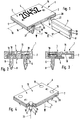
- the wrapping devices shown in FIGS. 8 to 13 are exemplary embodiments of the present invention. They are used to drive signing elements into wood, especially in tree trunks or the like. or parts of these. Such marking elements are shown by way of example in FIGS. 1 to 7, the wrapping devices also being suitable for other known marking elements.
- Each of these marking elements has a marking body which, in all of the illustrated embodiments, is in the form of a plate or plate.
- Each signature body 2 has a signature page 3, on which a signature 4 to be explained, which is indicated by way of example in FIGS. 1 to 7, is arranged.
- At least one fastening part 6 is arranged on a fastening side 5, which is located on the signature body side opposite the signature body in FIGS.
- the fastening parts 6 are fixedly arranged on the associated signing body 2 such that they protrude or protrude therefrom in the fastening direction indicated by arrow 7.
- the connection between the fastening parts 6 and the respective marking body 2 is preferably rigid.
- the respective marking element 1 with the free end regions pointing away from the marking body 2 - the anchoring ends 8 - of its fastening parts 6 is hammered into the wooden part with the aid of the inventive impact devices described later, where they remain firmly anchored.
- the signatures 4 of the individual signing elements 1 can be used to easily assign the marked wood to certain specifications.
- the fastening parts 6 can, in particular at their anchoring ends 8, be grooved or grooved in a barb-like manner or can be tooth-shaped or saw-tooth-shaped, as is the case with all of the exemplary embodiments shown.
- the signature body surfaces 15, 14 assigned to the signature side 3 and the opposite side are at least essentially flat.
- the signature bodies are therefore particularly easy to manufacture.
- the marking elements 1 according to FIGS. 1 to 6 are constructed in several pieces, the respective marking body 2 and the existing fastening parts 6 preferably being originally separate wooden components that are firmly connected to one another.
- the fastening parts 6 in the exemplary embodiments of FIGS. 1 and 3 to 6 are connected by pressing and in particular inseparably to the associated marking body 2, in FIG. 5 being prevented from falling out by positive locking.
- the fastening parts 6 can, e.g. in Fig. 2, be connected to the marking body by using adhesives which are paper and pulp friendly.
- a particularly secure connection between the fastening parts 6 and the marking body 2 is obtained if at least one mounting recess 18 is provided on the marking body, the fastening parts 6 each being seated and fastened in such a mounting recess 18 with complementary mounting parts 19 arranged in one piece on them.
- Such positive connections are realized in different embodiments in all embodiments according to FIGS. 1 to 6.
- two linear groove-shaped mounting recesses 18 are introduced into the marking body surface 14 on the fastening side 5, which are spaced apart and parallel to the longitudinal axis 16 of the marking body 2 or, in particular, at right angles thereto.
- the exemplary embodiment according to FIG. 1 is expediently provided with continuous mounting depressions 18 which open out at mutually opposite points on the circumferential narrow edge 20 of the marking body.
- the mounting recesses 18 are not continuous, but end with one axial side 22 in the wood before reaching the assigned edge of the marking body, while at the other end they open out to the assigned edge. It is expediently provided that the mounting recesses 18 open out on opposite edge sides of the marking body.
- the respective mouths expediently represent insertion openings 21, via which the fastening part 6 to be determined in each case has been inserted or can be inserted into the associated mounting recess 18 from the side.
- the fastening parts 6 have a substantially strip-like shape and their length corresponds e.g. as in FIG. 1, the length or width of the marking body 2 measured in the longitudinal direction of the associated mounting recess 18. Essentially, an essentially U-shaped cross section can thus be present, although the web connecting the two U-legs represented by the fastening parts 6 protrudes laterally in order to provide the mounting recesses 18 with wood material which delimits both sides.
- Length of the respective fastening part 6 is less than the correspondingly measured length or width dimension of the marking body.
- the length of the fastening part 6 is less than that of the mounting recess 18. The fastening part 6 axially abuts the end 22 of the mounting recess 18, so that an unoccupied section 26 of the mounting recess 18 remains on the side of the respective insertion or insertion opening 21.
- the indentation is easy to produce with a suitable indentation tool, it eliminates the need for additional joining agents such as glue. It practically prevents the fastening part from falling out by squeezing the edge opening.
- the respective fastening part 6 is immovably fixed due to at least one material squeeze or indentation provided on the marking body 2 in the longitudinal direction of the mounting recess receiving it.
- the outline of the marking body 2 is essentially rectangular and the mounting recesses are also parallel to one of the mutually parallel edge pairs.
- FIGS. 2 and 3 correspond in terms of their structure to that from FIG. 1. The only differences are in the design of the respective cooperating pairing of mounting recess 18 and mounting section 19.
- the mounting recesses 18 and mounting parts 19 have complementary dovetail profiles, so that the cross-sectional dimensions starting from the fastening side 5 in the direction of the signature side 3 also increase.
- the contours of the mounting recesses 18 and mounting parts 19, which are complementary to one another, being held in the form of a T. 2 the fastening parts 6 can be inserted into the mounting recesses 18 from the fastening side 5 because undercuts are avoided.
- the bracket section 19 and the bracket recesses 18 both have a rectangular cross section.
- the hold is expediently supported by adhesive, which can fill in the enlarged space shown.
- the mounting recesses 18 can have the shape of a circular segment with a circumferential angle extending over more than 180 °, as is indicated in FIG. 6.
- the flattening of the segment contour lies in the surface 14.
- the marking body 2 according to FIG. 6 can accordingly be e.g. be produced in that two parallel bores are made in a wooden strip, after which one strip side is removed over a certain depth.
- the number of fastening parts 6 per marking element 1 is not limited. It depends crucially on the embodiment of the fastening parts 6.
- these fastening parts 6 are designed in the form of a pin with a longitudinal axis 23 extending in the fastening direction 7.
- There are four fastening parts 6 of this type which are assigned to the four corner regions of the marking body 2, which is roughly rectangular in plan.
- only one fastening part 6 of this type is provided in the center region of the marking body.
- the mounting recesses 18 are openings from the signature side 3 to the mounting side 5, into which the mounting parts 6 with complementary mounting parts 19 are firmly inserted.
- the holding recesses 18 can also be blind hole-like recesses.
- the depressions or openings can taper conically, in which case a stop bead 28 can be assigned to the area with a smaller cross section on the part of the holder 19.
- the marking body 2 is formed by a laminated body which consists of a large number of overlapping wooden layers 24 of small thickness which are firmly bonded to one another by surface bonding.
- a laminated body which consists of a large number of overlapping wooden layers 24 of small thickness which are firmly bonded to one another by surface bonding.
- Such a laminate is characterized by particularly high strength, and the fastening parts 6 can, depending on requirements, be constructed in the manner described above or also as a laminate.
- the marking element 1 according to FIG. 7 is characterized by a one-piece construction. So it is a one-piece, possibly designed as a laminated body Wooden element in which both the marking body and the only fastening part 6 can be made from the full.
- the fastening part 6 is formed by an edge part of the marking body 2, so that the marking element is designed in the form of a strip with a wedge-shaped edge part.
- both signature body surfaces 14, 15 can be used to apply a signature.
- grooves 12, for example are provided as a means of preventing falling out of a signed wooden part.
- All of the marking elements according to FIGS. 1 to 6 preferably have in common that the course of the wood fibers 29 in the marking body 2 is directed transversely to the course of the fibers 30 of the fastening parts 6 likewise made of wood.
- the fibers 30 in the fastening parts 6 preferably run at least approximately in the fastening direction 7, so that they are directed at least substantially at right angles to the planes of the marking bodies 2 which are plate-shaped in the exemplary embodiments.
- the fibers 29 in the marking body 2 run transversely and in particular at right angles to the fastening direction 7 and, in the case of the plate-like embodiments, parallel to the plane of the plate.
- the fastening parts 6 are thereby practically only subjected to pressure, so that there is no risk of breakage.
- the fiber course in the marking body 2 ensures a high load-bearing capacity on the part of a tool that may be used when fastening to wood.
- the fiber course in the marking body 2 also serves to provide good support for the holder parts 19 in the region of the holder recesses 18.
- the mounting recesses 18 or the fastening parts 6 are expedient to assign the mounting recesses 18 or the fastening parts 6 to the axial end regions of the fibers 29 of the marking body 2, the mounting recesses 18 advantageously being arranged transversely to the fiber direction in the marking body 2.
- the marking elements made of wood material have hardened surface areas to increase the strength. This is the case, for example, in the embodiments according to FIGS. 1 and 7.
- the anchoring ends 8 are provided with a correspondingly hardened surface 37.
- the hardness results from the wooden material of the fastening parts 6 which has emerged and then dried wooden resins and / or binding agents. The escape of these wooden components has previously been forced in particular by heat which is generated in the course of a mechanical polishing, smoothing and / or grinding treatment.
- the surface areas, in particular areas of the anchoring ends 8, which are particularly stressed when struck into a wood to be signed, are heated, as a result of which resin and / or binding materials of a liquid or pasty nature emerge from the wood and stick to the surface.
- These leaking wood components are then allowed to harden or dry, which results in a surface hardness and smoothness or tempering.
- the heating is effected, in particular, in that the expediently conically tapering side surfaces of the anchoring ends 8 are processed, machined and practically abruptly or shock-like heated with a polishing, grinding or smoothing device, the latter in particular hot steel strips.
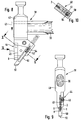
- a wrapping device 38, 38 ' is specially designed for wrapping the wood material marking elements described above into wood to be signed. Nevertheless, it can be used extremely universally, since it can also be used to drive in the usual signing elements from e.g. Plastic is suitable.
- the impact device 38, 38 ' is expediently designed in the manner of a hammer and has a handle 39, at one end of which a striking head 40, 40' is attached. On this there is a holding device 44, 44 'for the releasable arrangement of the signature element 1 to be driven into a wood. The same can be attached to the striking head 40, 40' in such a way that its fastening parts 6 protrude with the anchoring end 8 in the striking direction 43.
- the impact device 38 of FIGS. 8 to 10 is suitable for handling a strip-shaped marking element 1 as described with reference to FIG. 7.
- Its holding device 44 comprises, for example, a groove-shaped or slot-shaped receptacle 45, into which the marking element 1 with the marking body 2 can be inserted beforehand.
- a clamping element 46 for example in the form of a clamping screw which can be screwed to the striking head 40 transversely to the longitudinal direction of the receptacle 45, the marking element 1 can be captively fixed such that it is nevertheless released from the receptacle 45 with a certain tensile load acting in the striking direction 43.
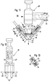
- the wrapping device 38 'of FIGS. 11 to 13 is provided for wrapping in signature elements 1 which correspond in structure to that of those described with reference to FIGS. 1 to 6.
- the respective signature element 1 is placed with the signature side 3 ahead of the striking head, where it is fixed via the holding device 44 '.
- the latter works in a pushing manner against at least two mutually opposite lateral edge areas 47 of the marking body 2.
- two pushing plungers 48 are provided, which in a e.g. bore-like guide 49 are slidably mounted and are pressed spring-loaded against the peripheral edge or the peripheral surface of the marking body 2. This results in a friction-locked holder which releases the respective element when the marking element 1 is subjected to a tensile load in the direction of impact 43.
- the impact device 38, 38 ' is guided with its striking head 40, 40' in the striking direction 43 against a wood to be signed, then the attached marking element 1 with the fastening part 6 penetrates into the wood, where it then remains because it is at the opposite impact head movement releases from the handle of the holding device 44, 44 '.
- the wrapping device 38, 38 ' according to the invention has at least one cutting element 50 for each fastening part 6, which in its starting position is upstream of the assigned fastening part of a marking element 1 attached to the striking head 40, 40' with a cutting part 51 in the direction of impact 43.
- the cutting elements 50 are elongated in the form of strips and are arranged so as to be displaceably guided on a guide device 52 fixed to the cutting head.
- the latter is expediently a recess 53 which extends through the striking head 40, 40 'and is open at both ends and into which a respective cutting element 50 is inserted.
- the cutting elements are expediently prestressed into the aforementioned starting position, which in the exemplary embodiments is accomplished by means of a spring 54 which acts on the one hand on one of the cutting elements 50 and on the other hand on the striking head 40, 40 '. It is preferably designed as a return spring.
- the cutting head 40, 40 ' is expediently divided in the region of a respective guide device 52 in the longitudinal direction thereof. This can be seen particularly well from FIGS. 10 and 13, which show a section transverse to the longitudinal extent of the guide device 52. It is thereby possible to bwz the striking head 40, 40 'for assembly. Disassembly of the cutting elements 50 and springs 54 to disassemble briefly.
- the cutting elements 50 are in the guide device receiving them movable back and forth.
- the arrangement is such that the existing cutting sections 51 are moved laterally out of the stroke of the associated fastening part 6 and in particular the entire marking element 1 when force is applied to them in the opposite direction 43.
- the cutting portions 51 preferably overlap with a movement against the direction of impact 43, so that the marking element 1 can be hammered into the wood to be signed without hindrance.
- the direction of the displacement movement carried out by the cutting elements 50 preferably runs at an acute angle to the striking direction 43, the axes of the two directions intersect in the region upstream of the fastening part of a marking element attached to the striking head. It is therefore expedient if the guide devices 52 are transverse to the direction of impact 43 are located in the area next to the existing holding device 44, 44 '.
- a single cutting element 50 with a cutting section 51 is provided.
- the cutting section 51 designed in the manner of a knife edge extends in the starting position in front of the anchoring end 8 essentially transversely to the direction of impact 43 in one plane with the fastening part 6.
- a fastening part 6 is of relatively long extension, it is expedient to provide two cutting elements 50 for this fastening part 6, which protrude from opposite sides into the stroke of the fastening part 6. Each cutting section 51 is then responsible for introducing a partial length of the required receiving recess.
- a corresponding arrangement has been made in the impact device 38 'according to FIGS. 11 to 13. In the starting position, viewed in side view transverse to the direction of impact 43, there is an approximately V-shaped arrangement of the cutting elements 50, the marking element 1 being arranged in the region of the tip of the V between the two V-legs.
- the cutting element pairs are likewise provided in a twofold arrangement on the striking head 40 ′, namely, as is clear from FIG. 12, adjacent to one another transversely to the striking direction 43. There are therefore four cutting elements 50, two pieces each being associated with a fastening part 6.
- the holding devices 44, 44' release the respective marking element 1 so that it remains on the marked wood.
- the cutting elements 50 move back into their starting position, which can be fixed by a suitable stop.
Landscapes
- Physics & Mathematics (AREA)
- General Physics & Mathematics (AREA)
- Engineering & Computer Science (AREA)
- Theoretical Computer Science (AREA)
- Life Sciences & Earth Sciences (AREA)
- Biodiversity & Conservation Biology (AREA)
- Ecology (AREA)
- Forests & Forestry (AREA)
- Environmental Sciences (AREA)
Priority Applications (1)
| Application Number | Priority Date | Filing Date | Title |
|---|---|---|---|
| EP93113872A EP0578281A1 (fr) | 1988-11-02 | 1990-06-06 | Dispositif d'enforcement pour éléments de marquage pour l'identification ou le numérotage du bois, en particulier trones d'arbre |
Applications Claiming Priority (2)
| Application Number | Priority Date | Filing Date | Title |
|---|---|---|---|
| DE19883837175 DE3837175C2 (de) | 1988-11-02 | 1988-11-02 | Signierelement |
| EP93113872A EP0578281A1 (fr) | 1988-11-02 | 1990-06-06 | Dispositif d'enforcement pour éléments de marquage pour l'identification ou le numérotage du bois, en particulier trones d'arbre |
Related Parent Applications (1)
| Application Number | Title | Priority Date | Filing Date |
|---|---|---|---|
| EP90110687.2 Division | 1990-06-06 |
Publications (1)
| Publication Number | Publication Date |
|---|---|
| EP0578281A1 true EP0578281A1 (fr) | 1994-01-12 |
Family
ID=25873811
Family Applications (1)
| Application Number | Title | Priority Date | Filing Date |
|---|---|---|---|
| EP93113872A Withdrawn EP0578281A1 (fr) | 1988-11-02 | 1990-06-06 | Dispositif d'enforcement pour éléments de marquage pour l'identification ou le numérotage du bois, en particulier trones d'arbre |
Country Status (1)
| Country | Link |
|---|---|
| EP (1) | EP0578281A1 (fr) |
Cited By (6)
| Publication number | Priority date | Publication date | Assignee | Title |
|---|---|---|---|---|
| FR2793994A1 (fr) * | 1999-05-25 | 2000-12-01 | Sylvain Chapotot | Dispositif de marquage des arbres |
| EP1693791A1 (fr) * | 2005-02-16 | 2006-08-23 | Johann Huber | Support en matière plastique avec transpondeur |
| WO2010072891A1 (fr) * | 2008-12-22 | 2010-07-01 | Valtion Teknillinen Tutkimuskeskus | Transpondeur, kit de transpondeur, procédé d'application du transpondeur et produit comprenant le transpondeur |
| EP2256715A1 (fr) * | 2009-05-29 | 2010-12-01 | Latschbacher GmbH | Plaquettes de signature du bois destinées à caractériser une grume et autre bois |
| FR2956770A1 (fr) * | 2010-02-24 | 2011-08-26 | Bernard Abel Andre Leuvrey | Plaquette d'identification des bois et moyens de fixation associes |
| SE2050719A1 (en) * | 2020-06-15 | 2021-12-16 | Soervik Bengt | Log marking device with a setting unit for the striking head |
Citations (2)
| Publication number | Priority date | Publication date | Assignee | Title |
|---|---|---|---|---|
| DE8904284U1 (de) * | 1989-04-06 | 1989-06-08 | Reinhardt, Hubert, 8011 Kirchseeon | Numerierstäbchen zum Kennzeichnen von Rohholz |
| DE9000653U1 (de) * | 1990-01-22 | 1990-03-29 | Reinhardt, Hubert, 8011 Kirchseeon | Markierungsstäbchen zum Numerieren von Rohholz |
-
1990
- 1990-06-06 EP EP93113872A patent/EP0578281A1/fr not_active Withdrawn
Patent Citations (2)
| Publication number | Priority date | Publication date | Assignee | Title |
|---|---|---|---|---|
| DE8904284U1 (de) * | 1989-04-06 | 1989-06-08 | Reinhardt, Hubert, 8011 Kirchseeon | Numerierstäbchen zum Kennzeichnen von Rohholz |
| DE9000653U1 (de) * | 1990-01-22 | 1990-03-29 | Reinhardt, Hubert, 8011 Kirchseeon | Markierungsstäbchen zum Numerieren von Rohholz |
Cited By (10)
| Publication number | Priority date | Publication date | Assignee | Title |
|---|---|---|---|---|
| FR2793994A1 (fr) * | 1999-05-25 | 2000-12-01 | Sylvain Chapotot | Dispositif de marquage des arbres |
| EP1693791A1 (fr) * | 2005-02-16 | 2006-08-23 | Johann Huber | Support en matière plastique avec transpondeur |
| WO2010072891A1 (fr) * | 2008-12-22 | 2010-07-01 | Valtion Teknillinen Tutkimuskeskus | Transpondeur, kit de transpondeur, procédé d'application du transpondeur et produit comprenant le transpondeur |
| US8511570B2 (en) | 2008-12-22 | 2013-08-20 | Teknologian Tutkimuskeskus Vtt | Transponder, transponder kit, method of applying the transponder and product comprising the transponder |
| EP2256715A1 (fr) * | 2009-05-29 | 2010-12-01 | Latschbacher GmbH | Plaquettes de signature du bois destinées à caractériser une grume et autre bois |
| FR2956770A1 (fr) * | 2010-02-24 | 2011-08-26 | Bernard Abel Andre Leuvrey | Plaquette d'identification des bois et moyens de fixation associes |
| SE2050719A1 (en) * | 2020-06-15 | 2021-12-16 | Soervik Bengt | Log marking device with a setting unit for the striking head |
| WO2021256974A1 (fr) * | 2020-06-15 | 2021-12-23 | Soervik Bengt | Dispositif de marquage de rondin avec une unité de réglage pour la tête de frappe |
| SE544160C2 (en) * | 2020-06-15 | 2022-02-08 | Soervik Bengt | Log marking device with a setting unit for the striking head |
| US12408600B2 (en) | 2020-06-15 | 2025-09-09 | Bengt Sörvik | Log marking device with a setting unit for the striking head |
Similar Documents
| Publication | Publication Date | Title |
|---|---|---|
| EP0274085B1 (fr) | Pince-papier en matière plastique | |
| EP0077932B1 (fr) | Dispositif pour assembler des tôles par une jonction similaire à une rivure | |
| EP0460256B1 (fr) | Dispositif de marquage, méthode de fabrication et dispositif pour son enfoncement | |
| DE1946587C3 (de) | Magazin an einem Nagler für kopflose Nägel | |
| DE102004042026A1 (de) | Spannvorrichtung zum werkzeuglosen Einspannen eines Sägeblatts | |
| WO2016005274A1 (fr) | Moyen d'assemblage et procédé de fixation d'un élément d'assemblage sur ou dans une pièce structurale | |
| EP1245860B1 (fr) | Dispositif de fixation d'agrafes de jonction de courroie à des courroies transporteuses | |
| DE3638048C2 (fr) | ||
| EP0578281A1 (fr) | Dispositif d'enforcement pour éléments de marquage pour l'identification ou le numérotage du bois, en particulier trones d'arbre | |
| DE19604243C2 (de) | Beschlag zum Verbinden von Bauteilen | |
| EP3030379B1 (fr) | Griffe de serrage pour dispositif de serrage | |
| DE1925461A1 (de) | Verfahren zur Herstellung von Metallplattengliedern fuer Gelenkplattenfoerderer | |
| DE1157856B (de) | Schwerspannstift | |
| DE2826874C2 (de) | Verbundprofil sowie Verfahren und Werkzeuge zu seiner Herstellung | |
| DE2432192A1 (de) | Kramme, und damit hergestelltes zusammengesetztes gebilde | |
| EP1604751B1 (fr) | Dispositif de poinçonnage et poinçon | |
| EP1153180A1 (fr) | Dispositif permettant de fendre les extremites d'un ensemble de fibres en matiere renforcee par des fibres | |
| EP1854602B1 (fr) | Dispositif pour couper à la longueur voulue des bandes de chant | |
| EP2626173B1 (fr) | Griffe de serrage pour un dispositif de serrage | |
| DE19505143C2 (de) | Meißelhalter | |
| DE2918350A1 (de) | Einspannbuchse | |
| DE102023128849A1 (de) | Industriemesser mit einem Grundkörper und einem auswechselbaren Schneidenteil | |
| DE29602020U1 (de) | Beschlag zum Verbinden von zwei Bauteilen | |
| DE1908368A1 (de) | Matrize fuer Eintreibgeraete von Befestigungsmitteln | |
| DE2811137C2 (de) | Stecker für Lichtleitfasern mit V-Nut-Führung |
Legal Events
| Date | Code | Title | Description |
|---|---|---|---|
| PUAI | Public reference made under article 153(3) epc to a published international application that has entered the european phase |
Free format text: ORIGINAL CODE: 0009012 |
|
| AC | Divisional application: reference to earlier application |
Ref document number: 460256 Country of ref document: EP |
|
| AK | Designated contracting states |
Kind code of ref document: A1 Designated state(s): AT CH DE FR GB IT LI SE |
|
| 17P | Request for examination filed |
Effective date: 19931202 |
|
| 18W | Application withdrawn |
Withdrawal date: 19940422 |