EP0578285B1 - Réclage actif de jeu des extrémités d'aubes de turbomachines - Google Patents
Réclage actif de jeu des extrémités d'aubes de turbomachines Download PDFInfo
- Publication number
- EP0578285B1 EP0578285B1 EP93200119A EP93200119A EP0578285B1 EP 0578285 B1 EP0578285 B1 EP 0578285B1 EP 93200119 A EP93200119 A EP 93200119A EP 93200119 A EP93200119 A EP 93200119A EP 0578285 B1 EP0578285 B1 EP 0578285B1
- Authority
- EP
- European Patent Office
- Prior art keywords
- rotor
- shroud
- turbomachine
- case
- wall
- Prior art date
- Legal status (The legal status is an assumption and is not a legal conclusion. Google has not performed a legal analysis and makes no representation as to the accuracy of the status listed.)
- Expired - Lifetime
Links
- 230000005291 magnetic effect Effects 0.000 claims description 18
- 230000005294 ferromagnetic effect Effects 0.000 claims description 3
- 230000004907 flux Effects 0.000 claims description 3
- 230000003247 decreasing effect Effects 0.000 claims 1
- 230000007423 decrease Effects 0.000 description 3
- 230000000694 effects Effects 0.000 description 3
- 238000013016 damping Methods 0.000 description 2
- 239000003302 ferromagnetic material Substances 0.000 description 2
- 239000002184 metal Substances 0.000 description 2
- 125000006850 spacer group Chemical group 0.000 description 2
- 230000007246 mechanism Effects 0.000 description 1
- 230000005012 migration Effects 0.000 description 1
- 238000013508 migration Methods 0.000 description 1
- 230000003068 static effect Effects 0.000 description 1
- 238000011144 upstream manufacturing Methods 0.000 description 1
Images
Classifications
-
- F—MECHANICAL ENGINEERING; LIGHTING; HEATING; WEAPONS; BLASTING
- F16—ENGINEERING ELEMENTS AND UNITS; GENERAL MEASURES FOR PRODUCING AND MAINTAINING EFFECTIVE FUNCTIONING OF MACHINES OR INSTALLATIONS; THERMAL INSULATION IN GENERAL
- F16C—SHAFTS; FLEXIBLE SHAFTS; ELEMENTS OR CRANKSHAFT MECHANISMS; ROTARY BODIES OTHER THAN GEARING ELEMENTS; BEARINGS
- F16C39/00—Relieving load on bearings
- F16C39/06—Relieving load on bearings using magnetic means
-
- F—MECHANICAL ENGINEERING; LIGHTING; HEATING; WEAPONS; BLASTING
- F01—MACHINES OR ENGINES IN GENERAL; ENGINE PLANTS IN GENERAL; STEAM ENGINES
- F01D—NON-POSITIVE DISPLACEMENT MACHINES OR ENGINES, e.g. STEAM TURBINES
- F01D11/00—Preventing or minimising internal leakage of working-fluid, e.g. between stages
- F01D11/08—Preventing or minimising internal leakage of working-fluid, e.g. between stages for sealing space between rotor blade tips and stator
- F01D11/14—Adjusting or regulating tip-clearance, i.e. distance between rotor-blade tips and stator casing
- F01D11/20—Actively adjusting tip-clearance
- F01D11/22—Actively adjusting tip-clearance by mechanically actuating the stator or rotor components, e.g. moving shroud sections relative to the rotor
-
- F—MECHANICAL ENGINEERING; LIGHTING; HEATING; WEAPONS; BLASTING
- F04—POSITIVE - DISPLACEMENT MACHINES FOR LIQUIDS; PUMPS FOR LIQUIDS OR ELASTIC FLUIDS
- F04D—NON-POSITIVE-DISPLACEMENT PUMPS
- F04D29/00—Details, component parts, or accessories
- F04D29/05—Shafts or bearings, or assemblies thereof, specially adapted for elastic fluid pumps
- F04D29/051—Axial thrust balancing
-
- F—MECHANICAL ENGINEERING; LIGHTING; HEATING; WEAPONS; BLASTING
- F04—POSITIVE - DISPLACEMENT MACHINES FOR LIQUIDS; PUMPS FOR LIQUIDS OR ELASTIC FLUIDS
- F04D—NON-POSITIVE-DISPLACEMENT PUMPS
- F04D29/00—Details, component parts, or accessories
- F04D29/05—Shafts or bearings, or assemblies thereof, specially adapted for elastic fluid pumps
- F04D29/052—Axially shiftable rotors
-
- F—MECHANICAL ENGINEERING; LIGHTING; HEATING; WEAPONS; BLASTING
- F16—ENGINEERING ELEMENTS AND UNITS; GENERAL MEASURES FOR PRODUCING AND MAINTAINING EFFECTIVE FUNCTIONING OF MACHINES OR INSTALLATIONS; THERMAL INSULATION IN GENERAL
- F16C—SHAFTS; FLEXIBLE SHAFTS; ELEMENTS OR CRANKSHAFT MECHANISMS; ROTARY BODIES OTHER THAN GEARING ELEMENTS; BEARINGS
- F16C32/00—Bearings not otherwise provided for
- F16C32/04—Bearings not otherwise provided for using magnetic or electric supporting means
- F16C32/0406—Magnetic bearings
- F16C32/044—Active magnetic bearings
- F16C32/0474—Active magnetic bearings for rotary movement
- F16C32/0476—Active magnetic bearings for rotary movement with active support of one degree of freedom, e.g. axial magnetic bearings
-
- F—MECHANICAL ENGINEERING; LIGHTING; HEATING; WEAPONS; BLASTING
- F05—INDEXING SCHEMES RELATING TO ENGINES OR PUMPS IN VARIOUS SUBCLASSES OF CLASSES F01-F04
- F05D—INDEXING SCHEME FOR ASPECTS RELATING TO NON-POSITIVE-DISPLACEMENT MACHINES OR ENGINES, GAS-TURBINES OR JET-PROPULSION PLANTS
- F05D2240/00—Components
- F05D2240/50—Bearings
- F05D2240/51—Magnetic
- F05D2240/515—Electromagnetic
-
- F—MECHANICAL ENGINEERING; LIGHTING; HEATING; WEAPONS; BLASTING
- F05—INDEXING SCHEMES RELATING TO ENGINES OR PUMPS IN VARIOUS SUBCLASSES OF CLASSES F01-F04
- F05D—INDEXING SCHEME FOR ASPECTS RELATING TO NON-POSITIVE-DISPLACEMENT MACHINES OR ENGINES, GAS-TURBINES OR JET-PROPULSION PLANTS
- F05D2240/00—Components
- F05D2240/50—Bearings
- F05D2240/52—Axial thrust bearings
-
- F—MECHANICAL ENGINEERING; LIGHTING; HEATING; WEAPONS; BLASTING
- F16—ENGINEERING ELEMENTS AND UNITS; GENERAL MEASURES FOR PRODUCING AND MAINTAINING EFFECTIVE FUNCTIONING OF MACHINES OR INSTALLATIONS; THERMAL INSULATION IN GENERAL
- F16C—SHAFTS; FLEXIBLE SHAFTS; ELEMENTS OR CRANKSHAFT MECHANISMS; ROTARY BODIES OTHER THAN GEARING ELEMENTS; BEARINGS
- F16C2360/00—Engines or pumps
- F16C2360/23—Gas turbine engines
Definitions
- This invention relates to tip-clearance control in gas turbine engines as specified in the preamble of claim 1, for example as disclosed in US-A-1,823,310.
- a shroud or surface thereof is moved towards and away from blade tips during engine operation to maintain a predetermined tip clearance.
- many prior proposals include a thermally-responsive shroud around blade tips, which shroud expands and contracts in accordance with selective exposure to hot gas behind the shroud.
- the inside diameter of a segmented shroud is controlled by balancing high-pressure air in a chamber behind the shroud against normal gas pressure on the opposite side of the shroud in a gas flow path of the turbomachine.
- a gas turbine engine or turbomachine includes novel, active tip-clearance control apparatus.
- a turbomachine according to the present invention is characterised by the features specified in the characterising portion of claim 1.
- This invention is a new improved turbomachine having a case, a shroud rigidly supported on the case, and a rotor supported on the case for rotation about a centreline of the case and for bodily-shiftable movement in the direction of the centreline.
- the rotor has a plurality of blades thereon, the tips of which flare radially outwards.
- the shroud has an outwardly-flared inner wall facing the blade tips and the gas flow path of the turbomachine so that bodily-shiftable movement of the rotor towards the shroud decreases the clearance between the blade tips and the inner wall of the shroud.
- An actuator on the case includes an electromagnet and a control system for modulating the magnetic attraction of the electromagnet on a thrust plate rigidly attached to the rotor.
- the magnetic attraction of the actuator is opposite in direction to the net dynamic force on the rotor.
- the control system includes position sensors on the case which provide signals corresponding to the instantaneous clearance between the blade tips and the shroud. The control system modulates the magnetic attraction of the actuator in response to the signals from the position sensors to maintain a substantially constant clearance between the shroud and the blade tips.
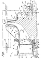
- a turbomachine in the form of a radial flow compressor 10 includes a case 12 having a front frame 14, a shroud 16, and a back plate 18, all rigidly connected together.
- An annular air inlet 20 of the compressor symmetrical about a longitudinal centreline 22 of the case, is defined between an outer wall 24 of the front frame and an inner dome 26 of the front frame.
- a plurality of radial struts support the inner dome 26 relative to the outer wall 24 and define guide vanes in the air inlet 20, only a single strut 28 being visible in Figure 1.
- the shroud 16 has a flange 30 for attachment to the front frame 14 and an inner wall 32 which flares radially outwards from a circular forward edge 34 to an outer circumferential edge 36.
- the back plate 18 of the case is symmetrical about the centreline 22 and is spaced axially from the shroud 16 so that a rotor chamber 38 is defined between the inner wall 32 of the shroud and an inner surface 40 of the back plate.
- An annular discharge 42 from the rotor chamber is defined between the circumferential edge 36 and the inner surface 40 of the back plate and may be surrounded by a diffuser (not shown) and a scroll chamber (not shown).
- a rotor 44 of the compressor 10 is aligned on the centreline 22 in the rotor chamber 38 and includes a hub 46 having an outer wall 48 facing the inner wall 32 of the shroud and flaring radially outwards from a front edge 50 of the rotor to a circumferential outer edge 52 of the rotor.
- the outer wall 48 and the inner wall 32 co-operate in defining therebetween an annular, outwardly-flaring gas flow path 54 extending from the inlet 20 to the discharge 42.
- a plurality of integral full blades and integral splitter blades of the rotor are disposed in the gas flow path 54, only a single full blade 56 and a single splitter blade 58 being visible in Figure 1.
- Each of the blades 56, 58 has an outwardly-flaring tip 60 spaced from the inner wall by a clearance gap 62 illustrated in exaggerated fashion for clarity in Figure 1.
- the rotor 44 is supported on the front frame 14 by a front bearing assembly 64 and on the back plate 18 by an aft bearing assembly 66 for rotation about the centreline 22 and for bodily-shiftable movement in the direction of the centreline.
- the front bearing assembly 64 includes a cup-shaped outer race 68, an annular inner race 70, and a plurality of rollers 72 therebetween.
- the outer race 68 is clamped to the dome 26 by a nut 74 on a stem 76 of the outer race 68.
- the inner race 70 is clamped on a cylindrical front extension 78 of the rotor 44 by a nut 80.
- the rollers 72 are effectively unrestrained for small excursions of the order of 0.762 mm (0.030 inch). Therefore, the rollers 72 also support the front extension 78 on the dome 26 for small excursions of bodily-shiftable movement in the direction of the centreline 22.
- the aft bearing assembly 66 includes an inner race 82, an outer race 84 and a plurality of anti-friction bearing balls 86 therebetween.
- the bearing balls 86 seat in respective grooves in the inner and outer races 82, 84 and, accordingly, prevent relative movement between the races in the direction of centreline 22.
- the inner race 82 is clamped on an aft extension 88 of the rotor 44 against a shoulder 90 on the hub 46 by a nut 92 with an annular thrust plate 94 and a tubular spacer 96 disposed on the aft extension 88 between the shoulder 90 and the inner race 82.
- the thrust plate 94 is made of ferromagnetic material.
- the aft extension 88 may be adapted for connection to a turbine shaft (not shown) for driving the rotor 44.
- An annular housing 98 of an electromagnetic actuator 100 is rigidly connected to the back plate 18 and, consequently, to the case 12 and includes a counter-bore 102 aligned on the centreline 22.
- the outer race 84 of the aft bearing assembly 66 is disposed in the counter-bore 102 with a spring washer 104 between the outer race 84 and the bottom of the counter-bore 102 and with a squeeze-film damping chamber defined in an annular clearance 106, illustrated in exaggerated fashion for clarity in Figure 1, around the outer race 84.
- the annular clearance 106 permits relative movement to occur between the actuator housing 98 on the one hand and the aft bearing assembly 66 and the rotor 44 on the other hand in the direction of the centreline 22.
- a retainer 108 on the actuator housing 98 limits movement of the outer race 84 to the right, as seen in Figure 1, under the influence of the spring washer 104 and, therefore, defines a retracted position of the rotor 44 relative to the shroud 16.
- the gap 62 between the blade tips 60 and the inner wall 32 of the shroud assumes a maximum dimension of the order of 0.381 mm (0.015 inch).
- the actuator 100 further includes an annular electromagnet 110 on the housing 98 flush with a side 112 thereof facing the thrust plate 94.
- the electromagnet includes a metal core and a wire coil connected to a power supply 114. When the electromagnet 110 is turned on, the power supply induces a current in the coil which produces a magnetic flux field which, in turn, intercepts the ferromagnetic thrust plate 94 and attracts the thrust plate and, consequently, the rotor 44 to the right towards the side 112 of the housing 98, as seen in Figure 1.
- the magnetic attraction of the actuator 100 is variable in accordance with the current flow through the coil of the electromagnet 110.
- a control system of the actuator 100 for modulating the power supply 114 and the magnetic attraction of the electromagnet includes a plurality of position sensors 116 on the shroud 16 and a programmable controller 118 connected to the sensors and to the power supply 114 for modulating the latter in response to signals from the sensors.
- a net dynamic force on the rotor 44 urges the rotor to the left as seen in Figure 1, so that the blade tips 60 are urged towards the inner wall 32 of the shroud.
- the net dynamic force is the result of migration of high-pressure air from the discharge 42 to the space behind the rotor and urges the rotor to an innermost position (not shown) achieved when the washer 104 is flattened between the bottom of the counterbore 102 and the outer race 84 of the bearing assembly 66. Clearance between the blade tips and the shroud is minimum in the innermost position of the rotor.
- the spring washer 104 also acts to keep the aft bearing assembly 16 loaded in the same direction as the direction of the magnetic attraction regardless of the magnetic attraction on the thrust plate.
- the sensors 116 provide signals to the programmable controller 118 characteristic of the instantaneous, real-time magnitude of the gap 62.
- the controller compares the real-time magnitude of the gap with a schedule of magnitudes calculated to maximize the efficiency of the compressor. Based on the comparison, the controller modulates the power supply 114 to increase or decrease the magnetic attraction of the electromagnet 110 on the thrust plate 94 to effect bodily-shiftable movement of the rotor 44 towards or away from the inside wall 32 of the shroud 16.
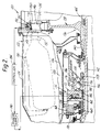
- a turbomachine in the form of a fragmentarily-illustrated axial flow gas turbine engine 120 includes a case 122 having an outer wall 124 and an inner wall 126 which define therebetween an annular compressed-air plenum 128.
- An annular combustor 130 in the compressed-air plenum 128 produces a continuous stream of hot gas which discharges from the combustor 130 through a stationary nozzle ring 132.
- the nozzle ring 132 defines an upstream end of an annular gas flow path 134 of the engine.
- a turbine rotor 136 of the engine 120 includes a turbine wheel 138 having a cylindrical hub 140 connected to a tubular rotor shaft 142 for rotation as a unit with the shaft 142 about a longitudinal centreline (not shown) of the engine.
- a fragmentarily-illustrated cylindrical hub 144 of a second turbine wheel (not shown) is similarly rigidly connected to the rotor shaft 142.
- the turbine wheel 138 has a circumferential array of turbine blades thereon in the gas flow path 134, only a representative blade 146 being visible in Figure 2.
- the turbine blades each have a radially outwardly-flaring blade tip 148 thereon in close proximity to a radially outwardly-flaring inner wall 150 of an annular shroud 152 rigidly supported on the case 122.
- a bearing assembly 154 of the engine 120 includes an inner race 156 on the rotor shaft 142 clamped by a nut 158 against a shoulder 160 of the rotor shaft 142 with an annular thrust plate 162 and additional seal runners and spacers between the inner race and the shoulder.
- the thrust plate 162 is made of ferromagnetic material.
- An outer race 164 of the bearing assembly 154 is disposed around the inner race 156 with a plurality of anti-friction bearing balls 166 therebetween.
- the bearing balls 166 seat in grooves in the races and, accordingly, prevent relative bodily-shiftable movement from occurring between the inner and outer races 156, 164 in the direction of the longitudinal centreline of the engine.
- An annular support 168 is bolted to a flange 170 integral with the inner wall 126 of the engine case.
- An annular actuator housing 172 of an electromagnetic actuator 174 is rigidly connected to the support 168 and includes an inner cylindrical wall 176 aligned on the longitudinal centreline of the engine, an annular surface 178 facing the thrust plate 162, and an annular shoulder 180 at an inward end of the cylindrical wall 176.
- the outer race 164 of the bearing assembly 154 is disposed in the annular housing 172 adjacent the cylindrical wall 176 with a spring washer 182 between the outer race 164 and the annular shoulder 180 on the housing 172.
- a squeeze-film damping chamber is defined in an annular clearance 184, illustrated in exaggerated fashion for clarity in Figure 2, around the outer race 164.
- the annular clearance 184 permits relative movement to occur between the actuator housing 172 on the one hand and the bearing assembly 154 and the rotor 136 on the other hand in the direction of the longitudinal centreline of the engine 120.
- a retainer 186 on the actuator housing 172 limits movement of the outer race 164 to the right, as seen in Figure 2, under the influence of the spring washer 182 and, therefore, defines a retracted position of the rotor 136 relative to the shroud 152.
- the gap between the blade tips 148 and the inner wall 150 of the shroud assumes a maximum dimension of the order of 0.762 mm (0.030 inch).
- the actuator 174 further includes an annular electromagnet 188 on the housing 172 flush with the surface 178 thereof facing the thrust plate 162.
- the electromagnet 188 includes a metal core and a wire coil connected to a power supply 190.
- the power supply 190 induces a current in the coil which produces a magnetic flux field which, in turn, intercepts the ferromagnetic thrust plate 162 and attracts the thrust plate and, consequently, the rotor 136 to the right towards the annular surface 178, as shown in Figure 2.
- a control system of the actuator for modulating the power supply 190 and the magnetic attraction of the electromagnet 188 includes a plurality of position sensors 192 on the shroud 152 and a programmable controller 194 connected to the sensors 192 and to the power supply 190 for modulating the latter in response to signals from the sensors 192.
- a net dynamic force on the rotor 136 urges the rotor to the left, as seen in Figure 2, to an innermost position (not shown) achieved when the washer 182 is flattened between the annular shoulder 180 and the outer race 164 of the bearing assembly 154. Clearance between the blade tips and the shroud is minimum in the innermost position of the rotor.
- the net dynamic force on the rotor is due to dynamic forces on a compressor, not shown, of the engine 120 connected to the shaft 142.
- the spring washer 182 also acts to keep the bearing assembly 154 loaded in the same direction as the direction of magnetic attraction, regardless of the magnetic attraction on the thrust plate 162.
- the sensors 192 provide signals to the programmable controller 194 characteristic of the instantaneous, real-time magnitude of the gap.
- the controller compares the real-time magnitude of the gap with a predetermined schedule of magnitudes. Based on the comparison, the controller modulates the power supply 190 to increase or decrease the magnetic attraction of the electromagnet 188 on the thrust plate 162 to effect bodily-shiftable movement of the rotor 136 in the direction of the longitudinal centreline of the engine.
Landscapes
- Engineering & Computer Science (AREA)
- General Engineering & Computer Science (AREA)
- Mechanical Engineering (AREA)
- Structures Of Non-Positive Displacement Pumps (AREA)
- Turbine Rotor Nozzle Sealing (AREA)
Claims (4)
- Turbomachine (10) comprenant : un carter (12) possédant une ligne médiane longitudinale (22), un anneau de renforcement annulaire (16) attaché de manière rigide audit carter (12) et possédant une paroi interne (32) définissant un côté d'un trajet annulaire d'écoulement (54) de gaz de ladite turbonachine (10) autour de ladite ligne médiane longitudinale (22) qui s'évase de manière radiale vers l'extérieur dans une direction en aval dudit trajet d'écoulement (54) de gaz, un rotor (44) possédant une pluralité de pales (56, 58) de rotor sur celui-ci, un moyen de palier (64, 66) montant ledit rotor (44) sur ledit carter (12), lesdites pales (56, 58) de rotor se trouvant dans ledit trajet d'écoulement (54) de gaz pour effectuer une rotation autour de ladite ligne médiane longitudinale (22) et pour effectuer un mouvement capable de déplacement en bloc dans la direction de ladite ligne médiane longitudinale (22) dans un premier sens en direction dudit anneau de renforcement (16) et dans un second sens opposé en éloignement dudit anneau de renforcement (16), ledit rotor (44) étant soumis à une force dynamique nette dans ledit premier sens pendant le fonctionnement de ladite turbomachine (10), chacune desdites pales (56, 58) de rotor possédant une pointe de pale (60) s'évasant de manière radiale vers l'extérieur dans la direction en aval dudit trajet d'écoulement (54) de gaz et coopérant avec ladite paroi interne (32) dudit anneau de renforcement (16) pour définir un espace de dégagement (62) entre celles-ci, lequel espace se réduit en réponse au mouvement capable de déplacement en bloc dudit rotor (44) dans ledit premier sens et augmente en réponse à un mouvement capable de déplacement en bloc dudit rotor (44) dans ledit second sens, et un moyen actuateur pour produire ledit mouvement capable de déplacement en bloc dudit rotor (44) dans ledit second sens, caractérisée en ce que ledit moyen actuateur comporte une plaque ferromagnétique de poussée (94) raccordée de manière rigide audit rotor (44) ; un moyen à électro-aimant (100) sur ledit carter (12) qui produit un champ de flux magnétique lorsqu'il est excité qui intercepte ladite plaque de poussée (94) et attire de manière magnétique ledit rotor (44) dans ledit second sens ; un moyen de détection de position (116) sur ledit carter (12) servant à générer un signal électrique pendant le fonctionnement de ladite turbomachine (10), qui correspond à la grandeur instantanée dudit espace de dégagement (62) entre lesdites pointes (60) de pale de rotor et ladite paroi interne (32) dudit anneau de renforcement (16) ; et un moyen de commande (114, 118) raccordé audit moyen à électro-aimant (100) et audit moyen de détection de position (116), qui sert à moduler l'attraction magnétique dudit moyen à électro-aimant (100) en réponse auxdits signaux en provenance dudit moyen de détection de position (116) de manière à maintenir un espace de dégagement (62) sensiblement constant entre lesdites pointes (60) de pale de rotor et ladite paroi interne (32) dudit anneau de renforcement (16) pendant le fonctionnement de ladite turbomachine (10).
- Turbomachine (10) selon la revendication 1, dans laquelle le moyen de palier montant ledit rotor (44) sur ledit carter (12) comporte un ensemble de palier (66) comprenant : une voie intérieure (82) attachée de manière rigide audit rotor (44), une voie extérieure (84), et une pluralité d'éléments anti-friction (86) entre ladite voie intérieure (82) et ladite voie extérieure (84) permettant une rotation relative entre ladite voie intérieure (82) et ladite voie extérieure (84) et d'empêcher un mouvement capable de déplacement en bloc relatif entre ladite voie intérieure (82) et ladite voie extérieure (84) dans la direction de ladite ligne médiane longitudinale (22).
- Turbomachine (10) selon la revendication 2, dans laquelle un moyen à ressort (104) est situé entre ledit carter (12) et ladite voie extérieure (84) dudit ensemble de palier (66) qui précharge ledit ensemble de palier (66) et ledit rotor (44) dans ledit second sens aet maintient une force nette sur ledit ensemble de palier dans ledit second sens sans tenir compte de l'attraction magnétique exercée par ledit moyen à électro-aimant (100) sur ladite plaque de poussée (94).
- Turbomachine (10) selon la revendication 3, dans laquelle ledit moyen à ressort est une rondelle élastique bombée annulaire (104) entre ledit carter (12) et ladite voie extérieure (84) dudit ensemble de palier (66), laquelle rondelle élastique bombée (104) a un état aplati qui définit une position la plus intérieure dudit rotor (44) par rapport audit anneau de renforcement (16) dans laquelle l'espace de dégagement (62) entre lesdites pointes (60) de pales de rotor et ladite paroi interne (32) dudit anneau de renforcement (16) est à un minimum.
Applications Claiming Priority (2)
| Application Number | Priority Date | Filing Date | Title |
|---|---|---|---|
| US901655 | 1992-06-22 | ||
| US07/901,655 US5263816A (en) | 1991-09-03 | 1992-06-22 | Turbomachine with active tip clearance control |
Publications (2)
| Publication Number | Publication Date |
|---|---|
| EP0578285A1 EP0578285A1 (fr) | 1994-01-12 |
| EP0578285B1 true EP0578285B1 (fr) | 1996-05-15 |
Family
ID=25414597
Family Applications (1)
| Application Number | Title | Priority Date | Filing Date |
|---|---|---|---|
| EP93200119A Expired - Lifetime EP0578285B1 (fr) | 1992-06-22 | 1993-01-18 | Réclage actif de jeu des extrémités d'aubes de turbomachines |
Country Status (4)
| Country | Link |
|---|---|
| US (1) | US5263816A (fr) |
| EP (1) | EP0578285B1 (fr) |
| CA (1) | CA2086170C (fr) |
| DE (1) | DE69302630T2 (fr) |
Families Citing this family (74)
| Publication number | Priority date | Publication date | Assignee | Title |
|---|---|---|---|---|
| FR2722836B1 (fr) * | 1994-07-20 | 1996-08-30 | Snecma | Turbomachine munie de moyens d'ajustement du jeu radial entre rotor e stator |
| US5658125A (en) * | 1995-02-28 | 1997-08-19 | Allison Engine Company, Inc. | Magnetic bearings as actuation for active compressor stability control |
| US5622045A (en) * | 1995-06-07 | 1997-04-22 | Allison Engine Company, Inc. | System for detecting and accommodating gas turbine engine fan damage |
| SE9701131D0 (sv) | 1997-03-26 | 1997-03-26 | Skf Nova Ab | Device for axial movement and high precixion positioning of arotatary shaft |
| WO1999028598A1 (fr) * | 1997-12-02 | 1999-06-10 | Siemens Aktiengesellschaft | Turbomachine et procede pour ajuster la largeur d'une fente radiale |
| US6142477A (en) * | 1998-11-16 | 2000-11-07 | United Technologies Corporation | Active seal |
| GB2345092B (en) * | 1998-12-24 | 2002-10-09 | Rolls Royce Plc | Fluid displacement apparatus |
| US6273671B1 (en) * | 1999-07-30 | 2001-08-14 | Allison Advanced Development Company | Blade clearance control for turbomachinery |
| KR100663640B1 (ko) * | 1999-08-27 | 2007-01-03 | 페블 베드 모듈러 리엑터(프로프라이어터리) 리미티드 | 시일 조립체, 가스 터빈과 시일 조립체의 조합체, 및 밀봉 표면들 사이의 간격이 일정하게 유지되도록 제어하는 방법 |
| US6367241B1 (en) | 1999-08-27 | 2002-04-09 | Allison Advanced Development Company | Pressure-assisted electromagnetic thrust bearing |
| US6502304B2 (en) * | 2001-05-15 | 2003-01-07 | General Electric Company | Turbine airfoil process sequencing for optimized tip performance |
| US6582195B2 (en) | 2001-06-27 | 2003-06-24 | General Electric Company | Compressor rotor blade spacer apparatus |
| EP1696103B1 (fr) * | 2002-05-14 | 2008-07-30 | Honda Giken Kogyo Kabushiki Kaisha | Turbine à gaz avec régulation active du jeu des extrémités des aubes |
| US6692222B2 (en) * | 2002-05-14 | 2004-02-17 | The Board Of Trustees Of The Leland Stanford Junior University | Micro gas turbine engine with active tip clearance control |
| GB2396438B (en) * | 2002-12-20 | 2006-03-22 | Rolls Royce Plc | Rotor system |
| JP2005201146A (ja) * | 2004-01-15 | 2005-07-28 | Denso Corp | 過給装置のポジション検出装置 |
| US7109595B2 (en) * | 2004-07-07 | 2006-09-19 | Yu-Lin Chung | Small multi-functional butane gas-powered portable electric generator |
| DE102004042258B3 (de) * | 2004-08-30 | 2006-01-19 | Daimlerchrysler Ag | Verfahren zur Herstellung eines Konturspalts sowie Strömungsmaschine mit einem Konturspalt |
| US7189059B2 (en) * | 2004-10-27 | 2007-03-13 | Honeywell International, Inc. | Compressor including an enhanced vaned shroud |
| DE102005018716A1 (de) * | 2005-04-21 | 2006-10-26 | Priebe, Klaus-Peter, Dipl.-Ing. | Dichtspaltregelung |
| US7575409B2 (en) * | 2005-07-01 | 2009-08-18 | Allison Advanced Development Company | Apparatus and method for active control of blade tip clearance |
| DE102005048982A1 (de) * | 2005-10-13 | 2007-04-19 | Mtu Aero Engines Gmbh | Vorrichtung und Verfahren zum axialen Verschieben eines Turbinenrotors |
| GB2440744B (en) | 2006-08-09 | 2008-09-10 | Rolls Royce Plc | A blade clearance arrangement |
| EP1908926A1 (fr) * | 2006-10-06 | 2008-04-09 | Siemens Aktiengesellschaft | Turbomachine |
| US7824151B2 (en) * | 2006-12-06 | 2010-11-02 | United Technologies Corporation | Zero running clearance centrifugal compressor |
| US7656135B2 (en) * | 2007-01-05 | 2010-02-02 | General Electric Company | Method and apparatus for controlling rotary machines |
| WO2008100844A1 (fr) * | 2007-02-14 | 2008-08-21 | Borgwarner Inc. | Carter de compresseur |
| US8839622B2 (en) | 2007-04-16 | 2014-09-23 | General Electric Company | Fluid flow in a fluid expansion system |
| DE102007032933B4 (de) * | 2007-07-14 | 2015-02-19 | Atlas Copco Energas Gmbh | Turbomaschine |
| DE102007035927A1 (de) * | 2007-07-31 | 2009-02-05 | Mtu Aero Engines Gmbh | Regelung für eine Gasturbine mit aktiv stabilisiertem Verdichter |
| BE1017777A3 (nl) * | 2007-10-09 | 2009-06-02 | Atlas Copco Airpower Nv | Verbeterde turbocompressor. |
| FR2933458B1 (fr) | 2008-07-01 | 2010-09-03 | Snecma | Compresseur axialo-centrifuge a systeme de pilotage |
| US8133003B2 (en) * | 2008-09-26 | 2012-03-13 | General Electric Company | Magnetic adjustment of turbomachinery components |
| US8087880B2 (en) * | 2008-12-03 | 2012-01-03 | General Electric Company | Active clearance control for a centrifugal compressor |
| US8177476B2 (en) * | 2009-03-25 | 2012-05-15 | General Electric Company | Method and apparatus for clearance control |
| BE1018544A3 (nl) * | 2009-04-28 | 2011-03-01 | Atlas Copco Airpower Nv | Inrichting voor het opnemen van een axiale kracht uitgeoefend op een as van een machine en een centrifugaalcompressor van zulke inrichting voorzien. |
| US8177483B2 (en) * | 2009-05-22 | 2012-05-15 | General Electric Company | Active casing alignment control system and method |
| US20100296912A1 (en) * | 2009-05-22 | 2010-11-25 | General Electric Company | Active Rotor Alignment Control System And Method |
| US8186945B2 (en) * | 2009-05-26 | 2012-05-29 | General Electric Company | System and method for clearance control |
| US8939715B2 (en) * | 2010-03-22 | 2015-01-27 | General Electric Company | Active tip clearance control for shrouded gas turbine blades and related method |
| US8400005B2 (en) | 2010-05-19 | 2013-03-19 | General Electric Company | Generating energy from fluid expansion |
| US8739538B2 (en) | 2010-05-28 | 2014-06-03 | General Electric Company | Generating energy from fluid expansion |
| US8593296B2 (en) * | 2010-10-19 | 2013-11-26 | General Electric Company | System and method for turbine bucket tip shroud deflection measurement |
| US8598751B2 (en) * | 2011-05-09 | 2013-12-03 | Honeywell International Inc. | Generator with integrated blower |
| US8801361B2 (en) * | 2011-08-10 | 2014-08-12 | Calnetix Technologies, Llc | Turbomachine wheel position control |
| US8840365B2 (en) * | 2011-12-21 | 2014-09-23 | Ford Global Technologies, Llc | Adjustable core turbocharger |
| US9018778B2 (en) | 2012-01-04 | 2015-04-28 | General Electric Company | Waste heat recovery system generator varnishing |
| US8984884B2 (en) | 2012-01-04 | 2015-03-24 | General Electric Company | Waste heat recovery systems |
| US9024460B2 (en) | 2012-01-04 | 2015-05-05 | General Electric Company | Waste heat recovery system generator encapsulation |
| US8769816B2 (en) | 2012-02-07 | 2014-07-08 | Siemens Aktiengesellschaft | Method of assembling a gas turbine engine |
| US20130315716A1 (en) * | 2012-05-22 | 2013-11-28 | General Electric Company | Turbomachine having clearance control capability and system therefor |
| US9206744B2 (en) | 2012-09-07 | 2015-12-08 | General Electric Company | System and method for operating a gas turbine engine |
| US10107121B2 (en) | 2012-12-05 | 2018-10-23 | Pratt & Whitney Canada Corp. | Carbon seal assembly |
| WO2014158285A2 (fr) * | 2013-02-26 | 2014-10-02 | United Technologies Corporation | Lame de séparateur à envergure variable |
| CN104214128B (zh) * | 2013-05-30 | 2017-05-17 | 高涵文 | 一种结构改进的磁力泵 |
| US10364694B2 (en) | 2013-12-17 | 2019-07-30 | United Technologies Corporation | Turbomachine blade clearance control system |
| KR101608130B1 (ko) * | 2014-01-14 | 2016-03-31 | 두산중공업 주식회사 | 블레이드 팁 간극 조절 수단을 구비한 가스 터빈 및 그 제어방법 |
| US9593589B2 (en) | 2014-02-28 | 2017-03-14 | General Electric Company | System and method for thrust bearing actuation to actively control clearance in a turbo machine |
| DE102015220333A1 (de) * | 2015-10-19 | 2017-04-20 | Rolls-Royce Deutschland Ltd & Co Kg | Vorrichtung zur Einstellung eines Spaltes zwischen dem Gehäuse eines Laufrades und dem Laufrad in einem Radialverdichter und eine Turbomaschine |
| US10408226B2 (en) * | 2016-05-26 | 2019-09-10 | Rolls-Royce Corporation | Segregated impeller shroud for clearance control in a centrifugal compressor |
| US10309410B2 (en) * | 2016-05-26 | 2019-06-04 | Rolls-Royce Corporation | Impeller shroud with deflecting outer member for clearance control in a centrifugal compressor |
| US10352329B2 (en) * | 2016-05-26 | 2019-07-16 | Rolls-Royce Corporation | Impeller shroud with thermal actuator for clearance control in a centrifugal compressor |
| US10458429B2 (en) | 2016-05-26 | 2019-10-29 | Rolls-Royce Corporation | Impeller shroud with slidable coupling for clearance control in a centrifugal compressor |
| WO2018174739A1 (fr) | 2017-03-21 | 2018-09-27 | Siemens Aktiengesellschaft | Système fournissant la mobilité d'un carénage de stator dans un étage de turbine |
| US10753223B2 (en) * | 2017-10-04 | 2020-08-25 | General Electric Company | Active centering control for static annular turbine flowpath structures |
| US10731666B2 (en) * | 2017-10-27 | 2020-08-04 | Rolls-Royce North American Technologies Inc. | Impeller shroud with closed form refrigeration system for clearance control in a centrifugal compressor |
| US10704560B2 (en) * | 2018-06-13 | 2020-07-07 | Rolls-Royce Corporation | Passive clearance control for a centrifugal impeller shroud |
| US11085319B2 (en) | 2019-06-21 | 2021-08-10 | Pratt & Whitney Canada Corp. | Gas turbine engine tip clearance control system |
| US11187247B1 (en) | 2021-05-20 | 2021-11-30 | Florida Turbine Technologies, Inc. | Gas turbine engine with active clearance control |
| US11746670B2 (en) * | 2021-12-27 | 2023-09-05 | Pratt & Whitney Canada Corp. | Impeller shroud assembly and method for operating same |
| US11655724B1 (en) | 2022-04-25 | 2023-05-23 | General Electric Company | Clearance control of fan blades in a gas turbine engine |
| US12421863B2 (en) * | 2023-07-21 | 2025-09-23 | Rtx Corporation | Turbine engine tip clearance control system with thrust bearing |
| US12345163B2 (en) | 2023-11-17 | 2025-07-01 | Rolls-Royce Corporation | Travel stop for a tip clearance control system |
| US12345162B2 (en) | 2023-11-17 | 2025-07-01 | Rolls-Royce Corporation | Adjustable position impeller shroud for centrifugal compressors |
Family Cites Families (19)
| Publication number | Priority date | Publication date | Assignee | Title |
|---|---|---|---|---|
| US1823310A (en) * | 1929-05-23 | 1931-09-15 | Westinghouse Electric & Mfg Co | Elastic fluid turbine |
| GB770375A (en) * | 1954-07-30 | 1957-03-20 | Adolf Roesch | Improvements in or relating to spindle bearings |
| US3045894A (en) * | 1957-05-22 | 1962-07-24 | Frederick W Ross | Gas turbine engine |
| FR1364037A (fr) * | 1963-05-06 | 1964-06-19 | Hispano Suiza Sa | Perfectionnements apportés aux joints d'étanchéité aux gaz pour machines tournantes, notamment pour compresseurs et turbines |
| US3329095A (en) * | 1965-11-16 | 1967-07-04 | Henning G Bartels | Booster pump |
| US3407740A (en) * | 1967-04-14 | 1968-10-29 | Borg Warner | Variable geometry centrifugal pump |
| DE2603882A1 (de) * | 1976-02-02 | 1977-08-04 | Gutehoffnungshuette Sterkrade | Schnellaufendes rotationssystem |
| GB2042646B (en) * | 1979-02-20 | 1982-09-22 | Rolls Royce | Rotor blade tip clearance control for gas turbine engine |
| US4264271A (en) * | 1979-03-15 | 1981-04-28 | Avco Corporation | Impeller shroud of a centrifugal compressor |
| US4332523A (en) * | 1979-05-25 | 1982-06-01 | Teledyne Industries, Inc. | Turbine shroud assembly |
| DE3044242A1 (de) * | 1979-12-11 | 1981-09-03 | Smiths Industries Ltd., London | Anzeigesystem zur anzeige des abstandes der blaetter einer turbine zu einem bezugspunkt |
| SU966306A1 (ru) * | 1980-12-15 | 1982-10-15 | Красноярский Политехнический Институт | Центробежный насос |
| JPS57105523A (en) * | 1980-12-24 | 1982-07-01 | Nippon Soken Inc | Supercharger for use in internal combustion engine |
| FR2528127A1 (fr) * | 1982-06-04 | 1983-12-09 | Creusot Loire | Moto-compresseur centrifuge electrique integre a grande vitesse |
| GB2165590B (en) * | 1984-10-09 | 1988-05-05 | Rolls Royce | Improvements in or relating to rotor tip clearance control devices |
| GB2169962B (en) * | 1985-01-22 | 1988-07-13 | Rolls Royce | Blade tip clearance control |
| WO1987000360A1 (fr) * | 1985-06-29 | 1987-01-15 | Hartmut Griepentrog | Machine comportant un rotor a paliers magnetiques et une machine electrique a champ radial |
| DE3536140A1 (de) * | 1985-10-10 | 1987-04-16 | Klein Schanzlin & Becker Ag | Kreiselpumpenaggregat |
| DE3740295A1 (de) * | 1987-11-27 | 1989-06-08 | Asea Brown Boveri | Axiales magnetlager |
-
1992
- 1992-06-22 US US07/901,655 patent/US5263816A/en not_active Expired - Fee Related
- 1992-12-23 CA CA002086170A patent/CA2086170C/fr not_active Expired - Fee Related
-
1993
- 1993-01-18 EP EP93200119A patent/EP0578285B1/fr not_active Expired - Lifetime
- 1993-01-18 DE DE69302630T patent/DE69302630T2/de not_active Expired - Fee Related
Also Published As
| Publication number | Publication date |
|---|---|
| DE69302630D1 (de) | 1996-06-20 |
| US5263816A (en) | 1993-11-23 |
| EP0578285A1 (fr) | 1994-01-12 |
| DE69302630T2 (de) | 1996-10-31 |
| CA2086170C (fr) | 1996-01-23 |
| CA2086170A1 (fr) | 1993-12-23 |
Similar Documents
| Publication | Publication Date | Title |
|---|---|---|
| EP0578285A1 (fr) | Réclage actif de jeu des extrémités d'aubes de turbomachines | |
| US5203673A (en) | Tip clearance control apparatus for a turbo-machine blade | |
| US6220602B1 (en) | Seal arrangement | |
| US5597286A (en) | Turbine frame static seal | |
| US6273671B1 (en) | Blade clearance control for turbomachinery | |
| US10935044B2 (en) | Segregated impeller shroud for clearance control in a centrifugal compressor | |
| US4425079A (en) | Air sealing for turbomachines | |
| US7334981B2 (en) | Counter-rotating gas turbine engine and method of assembling same | |
| US5035573A (en) | Blade tip clearance control apparatus with shroud segment position adjustment by unison ring movement | |
| US20020067870A1 (en) | Method and apparatus for supporting rotor assembly bearings | |
| US4687412A (en) | Impeller shroud | |
| US5330321A (en) | Rotor shroud assembly | |
| US7575409B2 (en) | Apparatus and method for active control of blade tip clearance | |
| US6543992B2 (en) | Control arrangement | |
| US10309410B2 (en) | Impeller shroud with deflecting outer member for clearance control in a centrifugal compressor | |
| US4668163A (en) | Automatic control device of a labyrinth seal clearance in a turbo-jet engine | |
| JP2010276019A (ja) | クリアランスを制御するためのシステム及び方法 | |
| JPH1089362A (ja) | 組み合わせ軸受装置 | |
| JPH0580574B2 (fr) | ||
| GB2103294A (en) | Shroud assembly for a gas turbine engine | |
| GB2445074A (en) | Gas turbine compressor foil thrust bearing | |
| EP1206657B1 (fr) | Ensemble d'etancheite | |
| US4248569A (en) | Stator mounting | |
| US10563539B2 (en) | Turbine engine with bearing assembly | |
| US20200191009A1 (en) | Turbine engine with floating shrouds |
Legal Events
| Date | Code | Title | Description |
|---|---|---|---|
| PUAI | Public reference made under article 153(3) epc to a published international application that has entered the european phase |
Free format text: ORIGINAL CODE: 0009012 |
|
| AK | Designated contracting states |
Kind code of ref document: A1 Designated state(s): DE FR GB |
|
| 17P | Request for examination filed |
Effective date: 19940215 |
|
| 17Q | First examination report despatched |
Effective date: 19950509 |
|
| GRAH | Despatch of communication of intention to grant a patent |
Free format text: ORIGINAL CODE: EPIDOS IGRA |
|
| GRAA | (expected) grant |
Free format text: ORIGINAL CODE: 0009210 |
|
| AK | Designated contracting states |
Kind code of ref document: B1 Designated state(s): DE FR GB |
|
| REF | Corresponds to: |
Ref document number: 69302630 Country of ref document: DE Date of ref document: 19960620 |
|
| ET | Fr: translation filed | ||
| PLBE | No opposition filed within time limit |
Free format text: ORIGINAL CODE: 0009261 |
|
| STAA | Information on the status of an ep patent application or granted ep patent |
Free format text: STATUS: NO OPPOSITION FILED WITHIN TIME LIMIT |
|
| 26N | No opposition filed | ||
| PGFP | Annual fee paid to national office [announced via postgrant information from national office to epo] |
Ref country code: FR Payment date: 20011210 Year of fee payment: 10 |
|
| PGFP | Annual fee paid to national office [announced via postgrant information from national office to epo] |
Ref country code: GB Payment date: 20011218 Year of fee payment: 10 |
|
| PGFP | Annual fee paid to national office [announced via postgrant information from national office to epo] |
Ref country code: DE Payment date: 20011219 Year of fee payment: 10 |
|
| REG | Reference to a national code |
Ref country code: GB Ref legal event code: IF02 |
|
| PG25 | Lapsed in a contracting state [announced via postgrant information from national office to epo] |
Ref country code: GB Free format text: LAPSE BECAUSE OF NON-PAYMENT OF DUE FEES Effective date: 20030118 |
|
| PG25 | Lapsed in a contracting state [announced via postgrant information from national office to epo] |
Ref country code: DE Free format text: LAPSE BECAUSE OF NON-PAYMENT OF DUE FEES Effective date: 20030801 |
|
| GBPC | Gb: european patent ceased through non-payment of renewal fee | ||
| PG25 | Lapsed in a contracting state [announced via postgrant information from national office to epo] |
Ref country code: FR Free format text: LAPSE BECAUSE OF NON-PAYMENT OF DUE FEES Effective date: 20030930 |
|
| REG | Reference to a national code |
Ref country code: FR Ref legal event code: ST |