EP0578414A1 - Lampe à vapeur de sodium à courant continu - Google Patents
Lampe à vapeur de sodium à courant continu Download PDFInfo
- Publication number
- EP0578414A1 EP0578414A1 EP93305011A EP93305011A EP0578414A1 EP 0578414 A1 EP0578414 A1 EP 0578414A1 EP 93305011 A EP93305011 A EP 93305011A EP 93305011 A EP93305011 A EP 93305011A EP 0578414 A1 EP0578414 A1 EP 0578414A1
- Authority
- EP
- European Patent Office
- Prior art keywords
- lamp
- anode
- arc
- cathode
- sodium
- Prior art date
- Legal status (The legal status is an assumption and is not a legal conclusion. Google has not performed a legal analysis and makes no representation as to the accuracy of the status listed.)
- Ceased
Links
Images


Classifications
-
- H—ELECTRICITY
- H01—ELECTRIC ELEMENTS
- H01J—ELECTRIC DISCHARGE TUBES OR DISCHARGE LAMPS
- H01J61/00—Gas-discharge or vapour-discharge lamps
- H01J61/02—Details
- H01J61/36—Seals between parts of vessels; Seals for leading-in conductors; Leading-in conductors
- H01J61/361—Seals between parts of vessel
- H01J61/363—End-disc seals or plug seals
-
- H—ELECTRICITY
- H01—ELECTRIC ELEMENTS
- H01J—ELECTRIC DISCHARGE TUBES OR DISCHARGE LAMPS
- H01J61/00—Gas-discharge or vapour-discharge lamps
- H01J61/02—Details
- H01J61/04—Electrodes; Screens; Shields
- H01J61/06—Main electrodes
- H01J61/073—Main electrodes for high-pressure discharge lamps
- H01J61/0735—Main electrodes for high-pressure discharge lamps characterised by the material of the electrode
- H01J61/0737—Main electrodes for high-pressure discharge lamps characterised by the material of the electrode characterised by the electron emissive material
-
- H—ELECTRICITY
- H01—ELECTRIC ELEMENTS
- H01J—ELECTRIC DISCHARGE TUBES OR DISCHARGE LAMPS
- H01J61/00—Gas-discharge or vapour-discharge lamps
- H01J61/02—Details
- H01J61/24—Means for obtaining or maintaining the desired pressure within the vessel
-
- H—ELECTRICITY
- H01—ELECTRIC ELEMENTS
- H01J—ELECTRIC DISCHARGE TUBES OR DISCHARGE LAMPS
- H01J61/00—Gas-discharge or vapour-discharge lamps
- H01J61/02—Details
- H01J61/30—Vessels; Containers
- H01J61/302—Vessels; Containers characterised by the material of the vessel
-
- H—ELECTRICITY
- H01—ELECTRIC ELEMENTS
- H01J—ELECTRIC DISCHARGE TUBES OR DISCHARGE LAMPS
- H01J61/00—Gas-discharge or vapour-discharge lamps
- H01J61/02—Details
- H01J61/30—Vessels; Containers
- H01J61/34—Double-wall vessels or containers
-
- H—ELECTRICITY
- H01—ELECTRIC ELEMENTS
- H01J—ELECTRIC DISCHARGE TUBES OR DISCHARGE LAMPS
- H01J61/00—Gas-discharge or vapour-discharge lamps
- H01J61/02—Details
- H01J61/52—Cooling arrangements; Heating arrangements; Means for circulating gas or vapour within the discharge space
- H01J61/523—Heating or cooling particular parts of the lamp
-
- H—ELECTRICITY
- H01—ELECTRIC ELEMENTS
- H01J—ELECTRIC DISCHARGE TUBES OR DISCHARGE LAMPS
- H01J61/00—Gas-discharge or vapour-discharge lamps
- H01J61/82—Lamps with high-pressure unconstricted discharge having a cold pressure > 400 Torr
- H01J61/825—High-pressure sodium lamps
Definitions
- This invention relates to a DC operated alkali metal vapor arc discharge lamp. More particularly, this invention relates to a DC operated sodium vapor arc discharge lamp comprising an elongated cylindrical arc tube having an electrode sealed in each end to form a cathode end and an anode end and containing a sodium amalgam and a noble starting gas, with the temperature at the cathode end at least 50°C greater than the temperature at the anode end and a cathode to anode sodium pressure ratio no greater than 5 during operation.
- High intensity alkali metal vapor arc discharge lamps such as high pressure sodium (HPS) arc discharge lamps are widely used for outdoor lighting because of their high efficacy as measured in lumens per watt.
- HPS high pressure sodium
- lighting systems employing HPS lamps often exhibit noticeable buzzing, light flicker and stroboscopic effects during operation from AC sources which can be annoying to the observer. This is especially noticeable with a standard 50-60 Hz line source.
- DC operation of such lamps, particularly on steady DC, will avoid the flickering problem but create other problems associated with cataphoresis.
- the cataphoresis phenomenon also occurs with low pressure metal vapor arc discharge lamps, such as fluorescent lamps which use mercury vapor and a noble gas in the light-emitting arc discharge.
- low pressure metal vapor arc discharge lamps such as fluorescent lamps which use mercury vapor and a noble gas in the light-emitting arc discharge.
- Some attempts have been made to overcome cataphoresis in DC operated fluorescent lamps.
- U.S. 3,117,248 discloses a feedback tube between the anode and cathode ends of the lamps and also suggests counteracting cataphoresis by increasing the wall temperature or current density.
- U.S. 3,617,792 a highly loaded and unsealed glass tube inside a fluorescent lamp envelope is employed to counteract cataphoresis.
- 4,698,549 discloses the use of an indium amalgam behind the anode in order to maintain a more even mercury distribution in a DC operated fluorescent lamp, but this will not work with an alkali metal vapor arc discharge lamp such as an HPS lamp. Moreover, it is not practical to use a feedback tube between anode and cathode ends for an HPS lamp nor is it practical to use an unsealed tube inside the arc tube to counteract for cataphoresis in such lamps. Hence, there is a need for a DC operated, high intensity alkali metal vapor arc discharge lamp and particularly one having an efficacy proximate that of an AC operated lamp of the same wattage.
- the present invention relates to a DC operated alkali metal vapor arc discharge lamp, such as a high pressure sodium (HPS) vapor lamp which comprises a linear, light transmissive arc chamber having a cathode at one end and an anode at the other end and containing an alkali metal amalgam and a starting gas, with the temperature at the cathode end at least 50°C and preferably at least 60°C higher than the anode end and a cathode to anode alkali metal vapor pressure ratio of no greater than 5 during operation of said lamp.
- the amalgam is an amalgam of alkali metal and mercury and preferably an amalgam which contains at least 20 wt. % of alkali metal.
- the arc chamber or tube is made of a suitable ceramic such as alumina.
- the cataphoretic driving parameter (CDP) will have a value of less than 150 and preferably less than 130.
- the CDP is the product of the arc current in amperes (I), times the arc gap length in centimeters (G), divided by the square of the inner diameter (B) of the arc tube in centimeters, or IG/B2.
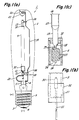
- FIG 1 schematically illustrates an HPS lamp useful in the practice of the invention.
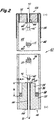
- Figure 2 is a sectional view of an HPS arc tube design useful in the present invention having an internal amalgam reservoir.
- Figure 3 graphically illustrates normalized efficacy for an HPS lamp as a function of the scaled sodium pressure.
- Figure 4 is a plot of the ratio of cathode end sodium pressure to anode end sodium pressure as a function of the cataphoretic driving parameter for a DC operated HPS lamp.
- an HPS lamp 1 useful in the practice of the invention is schematically illustrated as comprising a vitreous outer envelope 2 with a standard mogul screw base 3 attached to the stem end.
- a reentrant stem 4 has a pair of lead-in conductors 5 and 6 extending through it the outer ends of which are connected to the screw shell 7 and eyelet 8 of the base as a means of supplying electricity to the lamp.
- Arc tube or chamber 9 is a hollow tube of a light-transmitting ceramic tubing such as polycrystalline alumina which is translucent to light. Single crystal alumina, such as sapphire which is clear and transparent, may also be used.
- the cathode end of the arc chamber is closed by an alumina ceramic plug 10 through which extends niobium inlead wire 11 hermetically sealed in plug 10 for supporting the cathode 30 illustrated in Figure 1(b).
- the anode end of arc tube 9 illustrated in Figure 1(c) includes a ceramic plug 12 through which extends a thin-walled niobium tube 13 hermetically sealed into plug 12.
- the niobium tube 13 serves as an exhaust and fill tubulation during manufacture of the lamp, as a current inlead, as an external reservoir for excess sodium-mercury amalgam in the finished lamp, and as a support for anode 14.
- Tube 13 is hermetically pinch sealed at 26 which is the coldest portion of the overall arc chamber space.
- Flattened portion 27 is a capillary reservoir for excess amalgam external to arc tube 9.
- a sealing composition such as a mixture of alumina and calcia well known to those skilled in the art, is used to seal the ceramic end plugs 10 and 12 to the anode and cathode ends, respectively, of arc chamber 9 and also to seal niobium conductors 11 and 13 through the plugs.
- Figure 1(c) illustrates anode 14 which comprises tungsten wire 15 wound on a tungsten shank 16 in two layers.
- the shank is seized in the inwardly projecting end of niobium tube 13 either by crimping or by welding at 17; an aperture 18 allows passage of sodium-mercury amalgam vapor from the exhaust tube into the arc chamber or cavity of the arc tube 9.
- the electrodes are normally activated by alkaline earth metal compounds such as dibarium-calcium tungstate, retained in the interstices between turns of the coiling of the tungsten wire 15.
- the cathode end of the arc tube is illustrated as including niobium inlead wire 11 supporting cathode 30 which is similar in construction to anode 14.
- Niobium metal foil 32 is shown wrapped around the cathode end of the arc chamber as one means by which it is possible to increase the temperature at the cathode end in order to assist in achieving the temperature differential of at least 50°C required to avoid amalgam condensation at the cathode end during operation of the lamp.
- Arc tube 9 is mounted within outer envelope 2 by support rod 19 which extends the length of the outer envelope and is welded at one end to lead-in conductor 6 at the stem end with the other end braced by spring clamp 20 engaging dimple 21 in the dome end of the outer envelope 2.
- Conductor 22 is welded to niobium tube 13 and support rod 19 at the anode end of the arc tube.
- axial lead wire 11 extends through an insulating bushing 23 which is supported from rod 19 by means of metal strap 24. The aperture through the bushing allows free axial movement of inlead 11 and a flexible conductor 25 makes the electrical connection from the inlead to lead-in conductor 5. Differential thermal expansion is accommodated by axial movement of inlead 11 through bushing 23 and by flexing of curving conductor 25.
- arc chamber assembly 48 is shown as comprising hollow ceramic arc tube 42 enclosing arc chamber cavity 44 within having anode and cathode end closures 46 and 48, respectively.
- Anode and cathode end plugs 50 and 52, respectively, are also made of ceramic such as polycrystalline alumina or single crystalline (sapphire) alumina as is known to those skilled in the art.
- Anode plug 50 includes a pedestal portion 54 extending up from the region of commonality with the wall of ceramic tube 42 and defining with the wall an annular chamber or compartment 56 for holding unvaporized excess sodium-mercury amalgam shown at 58.
- the anode and cathode inlead assemblies 59 and 60 include niobium inlead wire 70 and 70' to which anode 59 and cathode 60 are attached by weld knots 72 and 72'. Both the anode 59 and cathode 60 comprise a tungsten shank 61 and 61' having two layers of tungsten wire 14 coiled around it to retain an electron emissive material such as dibarium calcium tungstate in the interstices between turns as for anode 14 in Figure 1(c). Niobium inlead wire is upset at 62 to provide a shoulder which serves to locate the anode and cathode with respect to the inner surface of the pedestal and plug, respectively.
- a cross wire 64 is spot welded to niobium inlead wire 10 to retain it in place and prevent it from falling out during sealing.
- a sealing frit or glass may be provided as a powder surrounding inlead wire 10 where it comes out of each plug or, preferably in the form of a washer of pressed powder which is threaded over the projecting portion of the wire. Upon heating, the frit melts, fills the aperture as illustrated at 66 and forms a small fillet 67 about the upset.
- Cathode end plug 52 is hermetically sealed to ceramic tube 42 by means of a suitable frit 21, whereas anode plug 66 is hermetically sealed to ceramic tube 42 by assembling plug 50 and tube 44 in the green state and then firing as taught in U.S.
- Patent 3,026,210 and 4,868,457 An HPS arc chamber assembly of this type suitable for use in the present invention is disclosed in U.S. 4,868,457 the disclosures of which are incorporated herein by reference.
- Niobium metal foil 32 is wrapped around the cathode end of arc chamber assembly 40 in order to raise the temperature at the cathode end so that the temperature differential between the cathode end and the anode end is at least 50°C and preferably at least 60°C.
- the total pressure in the arc chamber of an HPS lamp is constant along the length of the chamber for both an AC or a DC operated lamp.
- a pressure gradient of the alkali metal is established along the length of the arc chamber between the anode and cathode end.
- the lowest value of the alkali metal pressure occurs at the anode end, and in the DC lamp of the invention it is determined by the coldest spot in the chamber which is located behind the tip of the anode as is shown in Figures 1 and 2.
- any amalgam present in excess of that amount vaporized during lamp operation will be located as a condensed pool or reservoir at the coldest spot behind the tip of the anode.
- the coldest spot will be in the niobium metal tube 19 projecting behind the anode and external of the ceramic tube 9.
- the amalgam will be present behind the anode 59 in the cavity formed between the pedestal portion of the end 54 of the anode end plug and the inner wall of of the ceramic arc tube 42 and is shown as a pool 58.
- DC operated is meant steady DC, pulsed DC or a combination of steady state and pulsed DC operation.
- Plate 6(b) facing page 225 in "The High-Pressure Sodium Lamp" by deGroot and van Vliet (Philips Technical Library, 1966) is a photo of a DC operated HPS lamp containing sodium and mercury (and possibly a starting gas) which illustrates extreme cataphoretic separation between the sodium and the mercury.
- one-third of the arc discharge emits an orange color and the other two-thirds emits a blue color with a line of separation between the orange and blue colors.
- the orange emission is from sodium atoms and the blue emission is from mercury.
- the starting gas does not participate in the visible light emission.
- the cataphoretic action of the DC operated HPS arc discharge lamp altered the vapor composition along the length of the arc tube to produce a sodium rich composition at the cathode end and a mercury rich composition at the anode end which resulted in total color separation.
- the electrical resistance per unit length of the blue discharge is greater than that of the orange discharge, so that the power per unit length dissipated within the mercury rich portion of the discharge is substantially greater than normal. This situation results in overheating and failure of the arc tube and/or seal at the anode end.
- the blue discharge emits only about half the lumens per watt of the normal sodium discharge.
- the present invention overcomes these problems by keeping the cathode end of the arc chamber at least 50° and preferably at least 60°C higher than the anode end in order to maintain the amalgam location behind the tip of the anode, while keeping the cathode to anode alkali metal vapor pressure ratio below 5 during operation of the lamp by maintaining a CDP of less than 150.
- the temperature differential prevents condensation of the amalgam at the cathode end whereas the pressure ratio is driven by the CDP. It has been determined experimentally that the tendency for cataphoretic separation increases as the arc current increases, as the gap increases and as the bore diameter decreases.
- the cataphoretic driving parameter (CDP) which is the product of the RMS arc current in amperes times the length of the arc gap in centimeters, divided by the square of the diameter of the arc tube bore measured in centimeters will have a value less than 150 and preferably less than 130.
- the temperature of the cathode end of the arc tube during operation of the lamp can be increased in a number of ways, perhaps the most facile of which are to wrap a suitable metal foils (such as niobium, tantalum, molybdenum, platinum and the like) around the cathode end of the arc chamber and, if necessary, shorten the length of the cathode.
- the temperature at the anode end of the arc chamber can be reduced by lengthening the electrode so that the coldest spot of the anode end of the chamber is further away from the arc discharge ( Figure 2) and/or by employing an external reservoir for the amalgam such as the niobium tube illustrated in Figure 1.
- the outside surface of the niobium tube at the anode end may be roughened to dispel heat and a black, heat-emissive coating, such as graphite, also may be employed on both the anode end of the outside surface of the arc chamber and on the outer surface of the protruding niobium tube which contains the excess sodium amalgam.
- Employing these various methods can produce a temperature differential between the anode and cathode ends such that the cathode end is more than 100°C hotter than the anode end.
- Figure 3 is a plot of normalized efficacy as a function of relative sodium pressure based on experimental data for various AC operated HPS lamps where the lamp power was held constant while the amalgam cold spot temperature was varied with an independent heater circuit.
- the efficacy data were collected as a function of E/Eo, the arc electric field in volts per centimeter of arc gap length relative to the electric field value Eo which produced the optimum lamp efficacy at the lamp power employed.
- the arc gap length was measured as the distance between the tips of the two electrodes. It has been determined that the relative arc electric field E/Eo is approximately equal to the two-thirds (2/3) power of the relative sodium pressure P/Po in such an AC arc tube.
- relative sodium pressure is meant the actual sodium pressure, P, in the AC operated lamp divided by the optimum sodium pressure, Po, which yielded the greatest efficacy or lumens per watt output of the lamp.
- Figure 3 illustrates how the efficacy drops off as the actual sodium pressure becomes less than or more than the optimum sodium pressure.
- the sodium partial pressure will vary from the cathode end of the arc tube to the anode end of the arc tube with the sodium pressure being greatest at the cathode end of the arc tube.
- the total pressure that is, the sum of the sodium, mercury, and starting gas pressures, remains constant throughout the length of the arc tube irrespective of AC operation or DC operation.
- the ratio of the cathode (Pc) to anode (Pa) sodium pressure is 5, for example, then P/Po might be 0.5 at the anode end and 2.5 at the cathode. According to Figure 3, the efficacy at the ends of the discharge will be about 85% of that in the mid-portion where the sodium pressure is more nearly optimum.
- a DC-operated lamp will not be as efficient as AC, but the relative loss in efficiency can be minimized and color separation avoided by designing the lamp to keep Pc/Pa less than 5 by maintaining the CDP value below 150 and preferably below 130 and also by insuring that the cathode end is at least 50°C and preferably 60°C hotter than the anode end in order to prevent amalgam condensation at the cathode end, and to promote back-diffusion of the concentrated sodium vapor toward the anode end which has been depleted as a result of cataphoretic pumping toward the cathode end.
- a Lucalox® polycrystalline alumina ceramic HPS arc tube having a 5.5 mm bore was constructed as shown in Figure 1 with an outwardly protruding niobium tube.
- the arc chamber contained 25 mg of 25 wt. % sodium -75 wt. % mercury amalgam and 17 torr of xenon as a starting gas.
- the 25 mg of amalgam was in excess of the amount required to operate the lamp.
- the arc gap was 92 mm.
- This arc tube assembly was placed in an evacuated chamber. The temperature at each end of the arc tube was controlled by niobium wire wound around each end acting as heaters which permitted independent adjustment of the temperature at each end.
- the lamp was operated on steady DC at 382 watts, 109 volts and 3.5 amperes which corresponds to an electric field of 11.3 volts/cm and a wall loading of 23 watts/cm2 when end losses are accounted for.
- the coldest spot at the anode end measured as 629°C, it was found that sodium-enriched amalgam would start to condense at the cathode end at a temperature of 715°C. Thus, 86°C was found to be the minimum temperature differential required to avoid amalgam condensation at the cathode end of the arc tube.
- the CDP value of IG/B2 was 106.
- Sodium pressure at each end of the arc tube was determined from the temperature at each end and sodium vapor pressure curves.
- the cathode/anode sodium pressure ratio, Pc/Pa was determined to be 4.5.
- the coldest spot at the anode end was measured as 653°C (at end of niobium tube amalgam reservoir protruding outside of the arc tube).
- the cathode end was 203°C hotter than the anode end during lamp operation and the possibility of amalgam condensation at the cathode end was thereby eliminated.
- the cathode/anode sodium pressure ratio was 2.0. This was determined using the spectroscopic method employing the wavelength separation ⁇ between the maxima of the self-reversed sodium D- lines in the sodium arc discharge emission spectrum at each arc tube end. This method is known to those skilled in the art and may be found, for example, in section 3.2.1 "Sodium Vapour Pressure" beginning on page 84 of the book by deGroot and van Vliet referred to above.
- the CDP value for the lamp was 36.
- Figure 4 is a plot of the relative sodium pressure ratio Pc/Pa as a function of the cataphoretic driving parameter, CDP, using the data generated in these experiments.
- Another known data point has X- and Y- coordinates of 0 and 1, respectively, which corresponds to the case of an AC lamp, where there is no net cataphoretic driving force, and the sodium pressures at the cathode and anode ends are equal. The three points are seen to fit a straight line.
- Figure 4 shows that to obtain values of Pc/Pa less than 5 in order to maintain high lamp efficacy and to avoid problems associated with color separation and arc tube overheating, the CDP must be below 150.
Landscapes
- Discharge Lamp (AREA)
- Discharge Lamps And Accessories Thereof (AREA)
- Vessels And Coating Films For Discharge Lamps (AREA)
Applications Claiming Priority (2)
| Application Number | Priority Date | Filing Date | Title |
|---|---|---|---|
| US906802 | 1992-06-30 | ||
| US07/906,802 US5336968A (en) | 1992-06-30 | 1992-06-30 | DC operated sodium vapor lamp |
Publications (1)
| Publication Number | Publication Date |
|---|---|
| EP0578414A1 true EP0578414A1 (fr) | 1994-01-12 |
Family
ID=25423002
Family Applications (1)
| Application Number | Title | Priority Date | Filing Date |
|---|---|---|---|
| EP93305011A Ceased EP0578414A1 (fr) | 1992-06-30 | 1993-06-28 | Lampe à vapeur de sodium à courant continu |
Country Status (3)
| Country | Link |
|---|---|
| US (1) | US5336968A (fr) |
| EP (1) | EP0578414A1 (fr) |
| JP (1) | JPH0660848A (fr) |
Cited By (4)
| Publication number | Priority date | Publication date | Assignee | Title |
|---|---|---|---|---|
| EP0954010A1 (fr) * | 1998-04-28 | 1999-11-03 | General Electric Company | Enceinte à décharge en céramique pour lampe à décharge |
| EP1275128A4 (fr) * | 2000-01-20 | 2006-05-31 | Osram Sylvania Inc | Lampe a sodium a haute pression dotee d'une taille de tube arque reduite |
| WO2007023353A1 (fr) * | 2005-08-23 | 2007-03-01 | Space Cannon Vh S.P.A. | Lampe a decharge, alimentee en particulier en courant continu |
| WO2007107889A1 (fr) * | 2006-03-23 | 2007-09-27 | Koninklijke Philips Electronics N.V. | Dispositif a decharge de haute intensite ayant un metal a faible energie d'extraction dans l'espace de decharge |
Families Citing this family (11)
| Publication number | Priority date | Publication date | Assignee | Title |
|---|---|---|---|---|
| US5900696A (en) * | 1993-11-03 | 1999-05-04 | Osramisylvania Inc. | Incandescent lamp with shock resisting supports in the hollow legs of the envelope |
| US5680000A (en) * | 1995-11-07 | 1997-10-21 | Osram Sylvania Inc. | Reflective metal heat shield for metal halide lamps |
| WO1999050887A1 (fr) * | 1998-03-25 | 1999-10-07 | Toshiba Lighting & Technology Corporation | Lampe a decharge a haute pression, appareil la comprenant et source lumineuse |
| US6414436B1 (en) * | 1999-02-01 | 2002-07-02 | Gem Lighting Llc | Sapphire high intensity discharge projector lamp |
| DE19915920A1 (de) * | 1999-04-09 | 2000-10-19 | Heraeus Gmbh W C | Metallisches Bauteil und Entladungslampe |
| CN1240101C (zh) * | 2000-08-08 | 2006-02-01 | 余希湖 | 彻底消除直流荧光灯管“电泳效应”的方法 |
| US20050168148A1 (en) * | 2004-01-30 | 2005-08-04 | General Electric Company | Optical control of light in ceramic arctubes |
| US20060175973A1 (en) * | 2005-02-07 | 2006-08-10 | Lisitsyn Igor V | Xenon lamp |
| JP2011159543A (ja) * | 2010-02-02 | 2011-08-18 | Koito Mfg Co Ltd | 車輌用放電灯 |
| US8299697B2 (en) * | 2010-10-15 | 2012-10-30 | Qin Kong | High performance fluorescent lamp |
| DE102013102600A1 (de) * | 2013-03-14 | 2014-10-02 | Heraeus Noblelight Gmbh | Quecksilberdampfentladungslampe und Verfahren zu deren Herstellung |
Citations (3)
| Publication number | Priority date | Publication date | Assignee | Title |
|---|---|---|---|---|
| US3714492A (en) * | 1971-05-03 | 1973-01-30 | Gte Sylvania Inc | Dc fluorescent lamp with improved efficiency |
| EP0188229A2 (fr) * | 1985-01-14 | 1986-07-23 | General Electric Company | Fermeture d'extrémité en céramique pour lampe et structure pour entrée de courant |
| US4698549A (en) * | 1984-07-02 | 1987-10-06 | General Electric Company | D.C. lamp discharge gas pumping control |
Family Cites Families (11)
| Publication number | Priority date | Publication date | Assignee | Title |
|---|---|---|---|---|
| US3026210A (en) * | 1961-01-03 | 1962-03-20 | Gen Electric | Transparent alumina and method of preparation |
| US3117248A (en) * | 1961-05-18 | 1964-01-07 | Gen Electric | Low pressure mercury vapor discharge lamp for direct current operation |
| US3384798A (en) * | 1966-04-26 | 1968-05-21 | Gen Electric | High pressure saturation vapor sodium lamp containing mercury |
| US3453477A (en) * | 1967-02-16 | 1969-07-01 | Gen Electric | Alumina-ceramic sodium vapor lamp |
| US3617792A (en) * | 1969-02-24 | 1971-11-02 | Gen Electric | Highly loaded flourescent lamp particularly for dc operation |
| US4567396A (en) * | 1982-11-26 | 1986-01-28 | General Electric Company | Increased efficacy high pressure sodium lamp yielded by increased wall temperature operation |
| JPS60165038A (ja) * | 1984-02-08 | 1985-08-28 | Matsushita Electronics Corp | 螢光ランプ装置 |
| JPS60202654A (ja) * | 1984-03-27 | 1985-10-14 | Matsushita Electronics Corp | 螢光ランプ装置 |
| JPS61193356A (ja) * | 1985-02-20 | 1986-08-27 | Toshiba Corp | 低圧水銀蒸気放電灯の点灯方法 |
| JPS61135045A (ja) * | 1984-12-06 | 1986-06-23 | Matsushita Electronics Corp | 直流点灯用高圧ナトリウムランプ |
| US4639639A (en) * | 1985-04-23 | 1987-01-27 | North American Philips Corporation | High-pressure sodium vapor lamp and ternary amalgam therefor |
-
1992
- 1992-06-30 US US07/906,802 patent/US5336968A/en not_active Expired - Fee Related
-
1993
- 1993-06-25 JP JP5154662A patent/JPH0660848A/ja active Pending
- 1993-06-28 EP EP93305011A patent/EP0578414A1/fr not_active Ceased
Patent Citations (3)
| Publication number | Priority date | Publication date | Assignee | Title |
|---|---|---|---|---|
| US3714492A (en) * | 1971-05-03 | 1973-01-30 | Gte Sylvania Inc | Dc fluorescent lamp with improved efficiency |
| US4698549A (en) * | 1984-07-02 | 1987-10-06 | General Electric Company | D.C. lamp discharge gas pumping control |
| EP0188229A2 (fr) * | 1985-01-14 | 1986-07-23 | General Electric Company | Fermeture d'extrémité en céramique pour lampe et structure pour entrée de courant |
Non-Patent Citations (1)
| Title |
|---|
| PATENT ABSTRACTS OF JAPAN vol. 010, no. 039 (E-381)15 February 1986 & JP-A-60 195 862 ( MATSUSHITA ) 4 October 1985 * |
Cited By (4)
| Publication number | Priority date | Publication date | Assignee | Title |
|---|---|---|---|---|
| EP0954010A1 (fr) * | 1998-04-28 | 1999-11-03 | General Electric Company | Enceinte à décharge en céramique pour lampe à décharge |
| EP1275128A4 (fr) * | 2000-01-20 | 2006-05-31 | Osram Sylvania Inc | Lampe a sodium a haute pression dotee d'une taille de tube arque reduite |
| WO2007023353A1 (fr) * | 2005-08-23 | 2007-03-01 | Space Cannon Vh S.P.A. | Lampe a decharge, alimentee en particulier en courant continu |
| WO2007107889A1 (fr) * | 2006-03-23 | 2007-09-27 | Koninklijke Philips Electronics N.V. | Dispositif a decharge de haute intensite ayant un metal a faible energie d'extraction dans l'espace de decharge |
Also Published As
| Publication number | Publication date |
|---|---|
| US5336968A (en) | 1994-08-09 |
| JPH0660848A (ja) | 1994-03-04 |
Similar Documents
| Publication | Publication Date | Title |
|---|---|---|
| US4093893A (en) | Short arc fluorescent lamp | |
| US5336968A (en) | DC operated sodium vapor lamp | |
| US4734612A (en) | High pressure metal vapor discharge lamp | |
| US3781586A (en) | Long lifetime mercury-metal halide discharge lamps | |
| EP0758795A1 (fr) | Lampe fluorescente compacte contenant un amalgame à préchauffage amélioré | |
| US5905339A (en) | Gas discharge lamp having an electrode with a low heat capacity tip | |
| EP1472717A2 (fr) | Lampe a decharge de gaz | |
| US7348731B2 (en) | High-pressure gas discharge lamp with an asymmetrical discharge space | |
| WO2008072154A2 (fr) | Dispositif d'éclairage | |
| US7423379B2 (en) | High-pressure gas discharge lamp having tubular electrodes | |
| EP2149146B1 (fr) | Lampe à vapeur de sodium à haute pression | |
| JPH0527221B2 (fr) | ||
| JP3679256B2 (ja) | 放電灯 | |
| US20030025455A1 (en) | Ceramic HID lamp with special frame for stabilizing the arc | |
| Geens et al. | Progress in high pressure sodium lamp technology | |
| US3373303A (en) | Amalgam-containing fluorescent lamp with integral starting aid | |
| JPH048896B2 (fr) | ||
| US4074166A (en) | Ultraviolet emitting arc discharge lamp | |
| RU2077093C1 (ru) | Металлогалогенная лампа | |
| JPS61135045A (ja) | 直流点灯用高圧ナトリウムランプ | |
| CA1229127A (fr) | Absorbeur de gaz pour lampe a decharge fonctionnant en c.c. | |
| KR20080047470A (ko) | 방전관을 갖는 고압 방전 램프 | |
| JPH0584631B2 (fr) | ||
| JP2002298609A (ja) | 電球形蛍光ランプ | |
| JP2003162980A (ja) | 放電灯及び放電灯点灯装置 |
Legal Events
| Date | Code | Title | Description |
|---|---|---|---|
| PUAI | Public reference made under article 153(3) epc to a published international application that has entered the european phase |
Free format text: ORIGINAL CODE: 0009012 |
|
| AK | Designated contracting states |
Kind code of ref document: A1 Designated state(s): DE FR GB |
|
| 17P | Request for examination filed |
Effective date: 19940725 |
|
| 17Q | First examination report despatched |
Effective date: 19951215 |
|
| GRAG | Despatch of communication of intention to grant |
Free format text: ORIGINAL CODE: EPIDOS AGRA |
|
| STAA | Information on the status of an ep patent application or granted ep patent |
Free format text: STATUS: THE APPLICATION HAS BEEN REFUSED |
|
| 18R | Application refused |
Effective date: 19970517 |