EP0578485A2 - System zum Feststellen und Melden von Kollisionen - Google Patents
System zum Feststellen und Melden von Kollisionen Download PDFInfo
- Publication number
- EP0578485A2 EP0578485A2 EP93305318A EP93305318A EP0578485A2 EP 0578485 A2 EP0578485 A2 EP 0578485A2 EP 93305318 A EP93305318 A EP 93305318A EP 93305318 A EP93305318 A EP 93305318A EP 0578485 A2 EP0578485 A2 EP 0578485A2
- Authority
- EP
- European Patent Office
- Prior art keywords
- voltage
- comparator
- transmit
- network
- input port
- Prior art date
- Legal status (The legal status is an assumption and is not a legal conclusion. Google has not performed a legal analysis and makes no representation as to the accuracy of the status listed.)
- Withdrawn
Links
- 238000001514 detection method Methods 0.000 title claims abstract description 39
- 230000011664 signaling Effects 0.000 title claims abstract description 29
- 230000005540 biological transmission Effects 0.000 claims abstract description 38
- 238000000034 method Methods 0.000 claims abstract description 16
- 230000008569 process Effects 0.000 claims abstract description 9
- 230000003213 activating effect Effects 0.000 claims 2
- 238000010586 diagram Methods 0.000 description 13
- 239000003990 capacitor Substances 0.000 description 7
- 230000004044 response Effects 0.000 description 7
- 238000013500 data storage Methods 0.000 description 2
- 238000000926 separation method Methods 0.000 description 2
- 238000012935 Averaging Methods 0.000 description 1
- 206010000210 abortion Diseases 0.000 description 1
- 230000008901 benefit Effects 0.000 description 1
- 230000000740 bleeding effect Effects 0.000 description 1
- 239000004020 conductor Substances 0.000 description 1
- 230000000694 effects Effects 0.000 description 1
- 239000004973 liquid crystal related substance Substances 0.000 description 1
- 230000007246 mechanism Effects 0.000 description 1
- 238000012986 modification Methods 0.000 description 1
- 230000004048 modification Effects 0.000 description 1
- 230000000246 remedial effect Effects 0.000 description 1
- 239000004065 semiconductor Substances 0.000 description 1
Images


Classifications
-
- H—ELECTRICITY
- H04—ELECTRIC COMMUNICATION TECHNIQUE
- H04L—TRANSMISSION OF DIGITAL INFORMATION, e.g. TELEGRAPHIC COMMUNICATION
- H04L12/00—Data switching networks
- H04L12/28—Data switching networks characterised by path configuration, e.g. LAN [Local Area Networks] or WAN [Wide Area Networks]
- H04L12/40—Bus networks
- H04L12/407—Bus networks with decentralised control
- H04L12/413—Bus networks with decentralised control with random access, e.g. carrier-sense multiple-access with collision detection [CSMA-CD]
Definitions
- the present invention relates to a circuit for detecting collisions on a local area network and signalling the detection of collision.
- Packet switching is often used to allow multiple computing devices to communicate over a local area network. Using packet switching, a computing device is at all times connected to the network but transmits data in the form of individual packets. In Ethernet systems with data rates of 10 Megabits/second, for example, packets contain approximately 6,000 bits and are approximately 60 microseconds in duration.
- packets may be transmitted by any computing device on the network, collisions may occur when two devices transmit packets simultaneously. To insure the reliable transmission of data over the network, collisions must be detected so that remedial action, such as retransmission of the colliding packets, may be taken.
- One technique for detecting collisions is a listen-while-talk protocol. This system allows a device to begin transmitting a packet if no other transmission is detected on the network. Once the transmission of the packet begins, the transmitting device monitors the network for errors in its own transmission. If a collision occurs, the transmitting device detects an error in its transmission and aborts its transmission.
- Another technique for detecting collisions on a packet switching network uses a high-amplitude pulse embedded in the preamble of the packet.
- the minimum separation between successive high-amplitude pulses is the duration of a packet plus the delay between successive packets.
- a collision is detected when two high-amplitude pulses violate this minimum separation. Collisions resulting in coincident high-amplitude pulses, however, are not detected by this method.
- such collisions are detected by a secondary examination of the contents of the preamble, which contains a specified code. If the preamble does not contain the specified code upon receipt, a collision is detected.
- the above described techniques for detecting collisions require the device to read data from the network in digital format and compare the digital data to an expected value. Some such techniques also require the transmission of specialized collision detection data, or additional circuitry to create and detect specialized collision detection signals.
- this inexpensive collision detection device includes a light emitting diode to signal the detection of collisions.
- the invention in its broad form relates to a circuit as recited in claim 1.
- the invention relates to the use of a comparator and a peak detecting circuit to detect packet collisions.
- a circuit for detecting the transmission of packets on a network by a transceiver and signaling the detection of the transmission is also described herein.
- a light-emitting diode is lit, for at least a minimum duration, in response to the detection of packet collisions.
- a second light-emitting diode is lit, also for at least a minimum duration, in response to the detection of a packet transmission by a transceiver.
- a further aspect of the invention relates to a process for detecting collisions between packets being transmitted over a network and signaling the detection of collisions.
- Another aspect of the invention relates to a process for detecting the transmission of packets on a network by a transceiver and signaling the detection of the transmission.
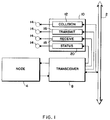
- Figure 1 is a block diagram showing the collision and transmit detectors in the context of a network environment.
- Figure 2A is an isometric diagram of the front of an enclosure with a transceiver and a circuit according to the principles of the invention.
- Figure 2B is an isometric diagram of the rear of the enclosure of Figure 2A.
- Figure 3 is a schematic diagram of a circuit according to the principles of the invention.
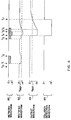
- Figure 4 is a timing diagram of selected waveforms related to the detection and signaling of collisions from the circuit of Figure 3.
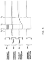
- Figure 5 is a timing diagram of selected waveforms related to the detection and signaling of transmissions from the circuit of Figure 3.
- the disclosed detection circuit detects collisions on a network resulting from overlapping transmissions by multiple nodes on a network, and activates a signaling device to signal the detection of collisions.
- the basic environment within which the invention operates is illustrated in the block diagram of Figure 1.
- Figure 1 shows a network 2 which carries electrically encoded messages, also known as packets, among nodes 4 which are tied to the network 2.
- the network 2 is a local area network, such as ETHERNET, and physically comprises a coaxial wire.
- the center conductor of the coaxial wire, which carries the network signals, is referred to as the medium, and is shown in Figure 3 as element 6.
- the node 4, which is typically a digital computer, may send or receive packets to or from other nodes on the network 2.
- the node 4 instead of being connected directly to the network 2, is coupled to the network 2 through a transceiver 8.
- the transceiver 8 translates the electrical waveforms carried by the medium 6 into signals which are more suitable for interpretation by the node 4.
- the signals carried between the node 4 and the transceiver 8 are square waves which alternate between +1.0 volt and -1.0 volt.
- the transceiver 8 also translates packets being sent from the node 4, which are encoded in a +/- 1.0 volt square wave signal, into the corresponding electrical waveforms carried by the medium 6.
- a detector group 10 works in conjunction with the transceiver 8 to detect and signal the status of the network 2 and the transceiver 8.
- the collision detector 12 monitors the medium 6 and activates a light-emitting diode 14 when two or more packets collide on the network 2.
- the mechanism for detecting and signaling such collisions is described in more detail in conjunction with Figures 3 and 4.
- the collision detector 12 may signal a collision with other visible or audible means, such as with a liquid crystal display or a speaker.
- the collision detector 12 may be coupled to a data storage device (not shown) to record the collision history of the network 2.
- the detector group 10 also includes a transmit detector 16, a receive detector 18, and a status detector 20.
- the transmit detector 16 monitors the transceiver 8 and activates a light-emitting diode 14 when the transceiver 8 transmits a packet.
- the receive detector 18 activates a light-emitting diode 14 when the transceiver 8 detects a packet on the network 2, and the status detector 20 activates a light-emitting diode 14 when power is supplied to the transceiver 8.
- the transmit, receive, and status detectors 14, 18, and 20 may signal their respective detections by other visible, audible, or data storage means, similar to those described for the collision detector 12.
- FIGS 2A and 2B show a transceiver/detector assembly 30 according to the invention.
- the transceiver 8 Housed within the transceiver/detector assembly 30 is the transceiver 8, the detector group 10, and the light-emitting diodes 14 of Figure 1.
- Also part of the transceiver/detector assembly 30 are ports 32 and 34 for connection to the network node 4 and to the network 2 respectively.
- the embodiment shown in Figures 2A and 2B may be plugged directly into a connector (not shown) on the network node 4, without the need for a connecting cable.
- the light emitting diodes 14 extend to the outer portion of the transceiver/detector assembly 30 such that they may be viewed by the user of the network node 4.
- the transceiver 8 and detector block 10 may be housed in separate enclosures (not shown.)
- the detector block 10 may also be housed within the enclosure containing the network node 4.
- the light-emitting diodes 14, or other signaling means may be made visible or otherwise accessible through apertures in the network node enclosure (not shown,) as appropriate.
- FIG. 3 shows a circuit embodying the collision detector 12 and the transmit detector 16.
- the circuit of Figure 3 includes a transceiver 8 which is based on a DP8392 integrated circuit 40 manufactured by National Semiconductor.
- An input port 7 of the transceiver 8 is connected to the medium 6, allowing the transceiver 8 to receive packets transmitted on the medium 6.
- An output port 9 of the transceiver 8 is connected to the medium 6 through a rectifier diode 42, the cathode terminal of the diode 42 being connected to the transceiver 8.
- the transceiver 8 normally holds the voltage potential of the cathode terminal of the diode 42 at ground.
- the diode 42 insulates the medium 6, which carries negative-going signals, from the transceiver 8. During a transmission, however, the transceiver 8 selectively asserts negative voltages at the cathode terminal of the diode 42, thus transmitting a packet on the medium 6.
- the collision detector 12 includes two comparators 44 and 46, each of which are supplied by voltages of ground and -9 volts.
- the positive input port of the first of the two collision comparators 44 is connected, through a resistor 48, to the anode terminal of a rectifier diode 50.
- the cathode terminal of the diode 50 is connected to the medium 6.
- the negative input port of the first collision comparator 44 is connected between voltage divider resistors 52 and 54.
- the voltage potential produced by the voltage divider is labeled as V ref1 .
- the output port of the first collision comparator 44 is connected to the positive input port of the second collision comparator 46.
- the output of the first collision comparator 44 is modified by a pulse stretcher, formed by resistor 56 and capacitor 58.
- the negative input port of the second collision comparator 46 is supplied by a reference voltage, which in Figure 3 is also generated by the voltage divider resistors 52 and 54.
- the output port of the second collision comparator 46 is then connected to the cathode terminal of the collision detection light-emitting diode 14, whose anode terminal is connected to ground through a resistor 59.
- the transmit detector 16 like the collision detector 12, includes two comparators 64 and 66, each of which are supplied by voltages of ground and -9 volts.
- the positive input port of the first of the two transmit comparators 64 is connected, through a resistor 68, to the transceiver output port 9.
- the negative input port of the first transmit comparator 64 is connected between voltage divider resistors 72 and 74.
- the voltage potential generated by the voltage divider is labeled V ref2 .
- the output of the first transmit comparator 64 is connected to the positive input port of the second transmit comparator 66.
- the output of the first transmit comparator 64 is modified by a pulse stretcher, formed by resistor 76 and capacitor 78.
- the negative input of the second comparator 66 is supplied by a reference voltage, V ref1 , which in Figure 3 is also generated by collision detector voltage divider resistors 52 and 54. This reference voltage may be generated independently from the collision voltage divider, but V ref1 is used in the embodiment of Figure 3 to reduce the component count.
- V ref1 a reference voltage
- the output port of the second transmit comparator 66 is then connected to the cathode terminal of the transmit detection light-emitting diode 14, whose anode terminal is connected to ground through resistor 79.
- the comparators 44, 46, 64, and 66 in the circuit of Figure 3 are LM339 integrated circuits.
- the first comparators 44 and 64 for each the collision and transmit detectors 12 and 16 must have input impedances sufficiently high to preserve the signal integrity of the medium 6.
- the input imped-ance must exceed 7.5 K ⁇ at 10 Mhz, and exceed 250 K ⁇ at D.C.
- the LM339 satisfies these criteria.
- the LM339 offers an additional functional advantage by bleeding off charge from the diode 50 at the positive input of the first collision comparator 44. This is discussed further in conjunction with Figure 4.
- Figure 4 shows a timing diagram of four waveforms for the collision detector 12. From top to bottom, the diagram includes the network waveform 80, the peak waveform 82, the output waveform 84, and the collision detection waveform 86.
- the network waveform 80 represents the voltage potential of the medium 6 during the transmission of packets on the network 2.
- the peak waveform 82 represents the voltage potential at the positive input port of the first collision detector comparator 44.
- the output waveform 84 represents the voltage potential at the output port of the first collision detector comparator 44 and at the positive input port of the second collision detector comparator 46.
- the collision detection waveform 86 represents the voltage potential applied to the cathode terminal of the light-emitting diode 14 for the collision detector 12.
- Figure 4 shows the medium 6 to have a voltage potential at ground. This indicates that no packets transmissions are detectable by the transceiver 8. Under this condition, the peak waveform 82 is also at ground.
- the reference voltage V ref1 is shown to be approximately -2.1 volts, as produced by voltage divider resistors 52 and 54 having values of approximately 10 K ⁇ and 3 K ⁇ respectively.
- the output waveform 84 With the peak waveform 82 at a voltage above V ref1 , the output waveform 84 is held at the ground potential. With the output waveform 84 also at a voltage above V ref1 , the collision detection waveform 86 is also held at the ground potential.
- the value of V ref1 is chosen such that normal packets on the medium x maintain a network waveform x voltage above V ref1 , but that colliding packets create a voltage below V ref1 .
- a packet is transmitted on the network 2, resulting in a signal between ground and approximately -2 volts on the medium 6.
- the negative-going signals of the network waveform 80 drive the peak waveform 82 to a voltage of approximately -1.2 volts.
- the diode 50 at the positive input of the first collision comparator 44 acts as a peak detector, holding the negative-going voltage extremes achieved by the network waveform 80.
- the peak waveform 82 decays toward ground as leakage current is drawn from the positive input of the first collision comparator 44.
- a low-cost comparator such as the LM339 integrated circuit used in the circuit of Figure 3, requires that the voltage at its inputs be separated by 1.5 volts or more from the respective voltage rail for proper operation. In the embodiment of Figure 3, this requires that V ref1 be less than -1.5 volts. This insures that the positive input of the first collision comparator 44 is more than 1.5 volts from ground when it crosses the reference voltage V ref1 . During some collisions between packets on the network 2, however, the average voltage does not fall below -1.48 volts. Therefore, an averaging circuit at the input of the first collision comparator 44, without the peak-detecting diode 50, would fail to detect these collisions.
- One alternative is to use a more expensive comparator which allows V ref1 to be closer to ground.
- the use of the peak-detecting diode 50 avoids the problem of undetected collisions while still allowing the use of a low-cost comparator, such as the LM339.
- the beginning of a packet transmission is again shown, and the network waveform 80 reacts as described above.
- a second packet transmission begins, overlapping with the first.
- the resulting network waveform 80 varies between ground and approximately -4 volts, which drives the peak waveform 82 to approximately -3.2 volts, due to the voltage drop across the diode 50.
- the first collision comparator 44 pulls the output waveform 84 to the low supply voltage of approximately -9 volts.
- the collision detection waveform 86 is also pulled to the low supply voltage of approximately -9 volts.
- the voltage potential generated across the collision light-emitting diode 14 by the collision detection waveform 86 causes the collision light-emitting diode 14 to be lit.
- the first packet transmission is completed, reducing the network waveform 80 to a minimum of approximately -2 volts.
- the peak waveform 82 then rises toward its potential prior to the packet overlap, -1.2 volts. This rise in voltage is due to a leakage current drawn from the positive input port of the first collision comparator 44.
- the peak waveform 82 rises past the V ref1 threshold. With its positive input exceeding its negative input, the first collision comparator 44 increases its output voltage toward its high supply voltage, which is at ground.
- the rise time of the output waveform 84 is increased by a pulse stretcher formed from a resistor 56 and a capacitor 58.
- the pulse stretcher is used to lengthen the time during which the collision light-emitting diode 14 is lit in response to a collision, to insure that it is visible to a person who is observing the collision light-emitting diode 14.
- the values of the resistor 56 and capacitor 58 are, respectively, 100 K ⁇ and 0.1 ⁇ f, resulting in a time constant of 10 ms.
- the output waveform 84 exceeds the V ref1 threshold, causing the positive input of the second collision comparator 46 to exceed its negative input.
- the voltage differential applied across the collision light-emitting diode 14 is thereby removed at time t7.
- the collision light-emitting diode 14 is lit from approximately time t4 through time t7. Due to the pulse stretching effect of the resistor 56 and capacitor 58, the collision light-emitting diode 14 may remain lit for more than 1000 times longer than the duration of a collision.
- FIG. 5 shows a timing diagram of four waveforms for the transmit detector 16. From top to bottom, the diagram includes the transmit waveform 90, the averaged waveform 92, the transmit output waveform 94, and the transmit detection waveform 96.
- the transmit waveform 90 represents the voltage potential applied to the cathode of diode 42 of Figure 3 by the transceiver 8 during the transmission of a packet by the transceiver 8.
- the averaged waveform 92 represents approximately the average of the transmit waveform 90, and is measured at the positive input of the first transmit comparator 64.
- the transmit output waveform 94 represents the voltage potential at the output of the first transmit detector comparator 64 and at the positive input of the second transmit detector comparator 66.
- the transmit detection waveform 96 represents the voltage potential applied to the cathode terminal of the light-emitting diode 14 for the transmit detector 16.
- the transceiver 8 maintains a voltage potential of ground at the cathode terminal of the diode 42 during periods when the transceiver 8 is not transmitting packets on the network 2.
- the reference voltage V ref2 is shown to be approximately -1.8 volts, as produced by voltage divider resistors 72 and 74 having values of approximately 10 K ⁇ and 2.49 K ⁇ respectively.
- the transmit output waveform 94 is held at the ground potential.
- the value of V ref2 is chosen such that the voltage of the averaged waveform 92 is less than V ref2 only while the transceiver 8 is transmitting packets on the network 2.
- the collision detection waveform 96 is also held at the ground potential.
- the transceiver 8 begins transmitting a packet and asserts a signal which causes the transmit waveform 90 to vary between approximately -0.8 volts and -3 volts.
- the averaged waveform 92 drops from ground to approximately -1.9 volts, as shown in Figure 5.
- the first transmit comparator 64 pulls the transmit output waveform 94 to the low supply voltage of approximately -9 volts.
- the transmit detection waveform 96 is also pulled to the low supply voltage of approximately -9 volts. The voltage potential generated across the transmit light-emitting diode 14 by the transmit detection waveform 96 causes the transmit light-emitting diode 14 to be lit.
- the transceiver 8 completes its transmission and reasserts a ground potential on the transmit waveform 90.
- the first transmit comparator 64 increases its output voltage toward its high supply voltage, which is at ground.
- the rise time of the transmit output waveform 94 is increased by a pulse stretcher formed from a resistor 76 and a capacitor 78.
- the pulse stretcher is used to lengthen the time during which the transmit light-emitting diode 14 is lit in response to a transmission by the transceiver 8 to insure that it is visible to a person who is observing the transmit light-emitting diode 14.
- the values of the resistor 76 and capacitor 78 are, respectively, 100 K ⁇ and 0.1 ⁇ f, resulting in a time constant of 10 ms.
- the transmit output waveform 94 exceeds the V ref1 threshold, causing the positive input of the second transmit comparator 66 to exceed its negative input.
- the voltage differential applied across the transmit light-emitting diode 14 is thereby removed at time t3.
- the transmit light-emitting diode 14 is lit from approximately time t1 through time t3. Similar to the operation of the collision light-emitting diode 14, the transmit light-emitting diode 14 is lit for a duration to allow it to be easily observed by a person.
Landscapes
- Engineering & Computer Science (AREA)
- Computer Networks & Wireless Communication (AREA)
- Signal Processing (AREA)
- Small-Scale Networks (AREA)
Applications Claiming Priority (2)
| Application Number | Priority Date | Filing Date | Title |
|---|---|---|---|
| US909921 | 1992-07-07 | ||
| US07/909,921 US5267237A (en) | 1992-07-07 | 1992-07-07 | Collison detection and signaling circuit |
Publications (2)
| Publication Number | Publication Date |
|---|---|
| EP0578485A2 true EP0578485A2 (de) | 1994-01-12 |
| EP0578485A3 EP0578485A3 (en) | 1995-12-13 |
Family
ID=25428049
Family Applications (1)
| Application Number | Title | Priority Date | Filing Date |
|---|---|---|---|
| EP93305318A Withdrawn EP0578485A3 (en) | 1992-07-07 | 1993-07-07 | Collision detection and signaling circuit |
Country Status (2)
| Country | Link |
|---|---|
| US (1) | US5267237A (de) |
| EP (1) | EP0578485A3 (de) |
Cited By (1)
| Publication number | Priority date | Publication date | Assignee | Title |
|---|---|---|---|---|
| GB2330740A (en) * | 1997-08-29 | 1999-04-28 | 3Com Technologies Ltd | Network monitoring display |
Families Citing this family (4)
| Publication number | Priority date | Publication date | Assignee | Title |
|---|---|---|---|---|
| EP0489990A1 (de) * | 1990-12-07 | 1992-06-17 | Hewlett-Packard Company | Verfahren and Vorrichtung zur Überwachung eines lokalen Netzes |
| KR970011839B1 (ko) * | 1994-03-15 | 1997-07-16 | 엘지반도체 주식회사 | 근거리통신망의 데이타충돌 검출회로 |
| US5596568A (en) * | 1995-06-02 | 1997-01-21 | Mci Communications Corporation | Apparatus for protecting a telecommunications network from false alarm conditions due to T1 line signal interruption |
| US6741168B2 (en) * | 2001-12-13 | 2004-05-25 | Samsung Electronics Co., Ltd. | Method and apparatus for automated collection and transfer of collision information |
Family Cites Families (11)
| Publication number | Priority date | Publication date | Assignee | Title |
|---|---|---|---|---|
| US4210780A (en) * | 1978-03-27 | 1980-07-01 | The Mitre Corporation | Multiple access digital communications system |
| JPS59115645A (ja) * | 1982-12-22 | 1984-07-04 | Toshiba Corp | 情報伝送方式 |
| JPS59202753A (ja) * | 1983-05-02 | 1984-11-16 | Toshiba Corp | デ−タ通信システム |
| US4561091A (en) * | 1983-09-23 | 1985-12-24 | Codenoll Technology Corporation | Data receiver |
| US4602364A (en) * | 1984-04-23 | 1986-07-22 | Codex Corporation | Local area data communication network |
| AU583316B2 (en) * | 1984-11-13 | 1989-04-27 | Alcatel N.V. | Apparatus for masterless collision detection |
| EP0216214B1 (de) * | 1985-09-25 | 1991-05-08 | Siemens Aktiengesellschaft | Verfahren zum automatischen Pegelabgleich in einem lokalen Netz, insbesondere für eine Mehrrechneranordnung, mit einem Bussystem mit Lichtwellenleitern, zum Zwecke einer Kollisionserkennung |
| US4779088A (en) * | 1985-11-18 | 1988-10-18 | American Telephone And Telegraph Company | Collision detection arrangement for daisy chain configurations |
| US4734596A (en) * | 1986-04-03 | 1988-03-29 | Advanced Micro Devices, Inc. | Detection of direct current in the presence of manchester-encoded signals |
| US4888763A (en) * | 1988-03-11 | 1989-12-19 | Codenoll Technology Corporation | Method and apparatus for detecting the collision of data packets utilizing a preassigned transceiver code in the preamble |
| US5124982A (en) * | 1990-02-27 | 1992-06-23 | Allied Telesis, Incorporated | Multiple port medium attachment unit for a network |
-
1992
- 1992-07-07 US US07/909,921 patent/US5267237A/en not_active Expired - Lifetime
-
1993
- 1993-07-07 EP EP93305318A patent/EP0578485A3/en not_active Withdrawn
Cited By (3)
| Publication number | Priority date | Publication date | Assignee | Title |
|---|---|---|---|---|
| GB2330740A (en) * | 1997-08-29 | 1999-04-28 | 3Com Technologies Ltd | Network monitoring display |
| GB2330740B (en) * | 1997-08-29 | 2000-01-26 | 3Com Technologies Ltd | Network hub activity display |
| US6256318B1 (en) | 1997-08-29 | 2001-07-03 | 3Com Corporation | Network hub activity display |
Also Published As
| Publication number | Publication date |
|---|---|
| EP0578485A3 (en) | 1995-12-13 |
| US5267237A (en) | 1993-11-30 |
Similar Documents
| Publication | Publication Date | Title |
|---|---|---|
| US4890102A (en) | Visual display for communication network monitoring and troubleshooting | |
| US4797901A (en) | Circuit arrangement for testing a passive bus network with the carrier sense multiple access with collisions detection method | |
| CA1299269C (en) | Smoke and fire detection system communication | |
| US5428640A (en) | Switch circuit for setting and signaling a voltage level | |
| US6384723B1 (en) | Digital communication system and method | |
| US5185735A (en) | Lan noise monitor | |
| US5079766A (en) | Access unit to a local network transmission medium | |
| JPH0527289B2 (de) | ||
| US5267237A (en) | Collison detection and signaling circuit | |
| EP1230683A4 (de) | I2c opto-isolator-schaltung | |
| US5329519A (en) | Lan monitoring method and apparatus | |
| JP2988529B2 (ja) | 故障診断装置 | |
| US6163263A (en) | Circuitry for electrical device in multi-device communications system | |
| JPH0741232Y2 (ja) | 非同期2進データ通信回路 | |
| US5043722A (en) | Detector for colliding signals in asynchronous communication | |
| US4779088A (en) | Collision detection arrangement for daisy chain configurations | |
| US6407402B1 (en) | I2C opto-isolator circuit | |
| EP0324012B1 (de) | Koaxialkabelkurzschlussdetektor für lokale netze | |
| HU200881B (en) | System for identifying moving objects | |
| US4463345A (en) | Seed flow monitor | |
| JPS59158148A (ja) | デ−タ伝送装置 | |
| JPS58215837A (ja) | 光受信回路 | |
| EP0381385A2 (de) | Detektor für zusammenstossende Signale in einer asynchronen Kommunikation | |
| US6462325B1 (en) | Circuit for detecting the shutoff of an optical output | |
| JPH07118725B2 (ja) | パルス伝送方式 |
Legal Events
| Date | Code | Title | Description |
|---|---|---|---|
| PUAI | Public reference made under article 153(3) epc to a published international application that has entered the european phase |
Free format text: ORIGINAL CODE: 0009012 |
|
| AK | Designated contracting states |
Kind code of ref document: A2 Designated state(s): DE FR GB IT |
|
| PUAL | Search report despatched |
Free format text: ORIGINAL CODE: 0009013 |
|
| AK | Designated contracting states |
Kind code of ref document: A3 Designated state(s): DE FR GB IT |
|
| 17P | Request for examination filed |
Effective date: 19960108 |
|
| 17Q | First examination report despatched |
Effective date: 19961115 |
|
| STAA | Information on the status of an ep patent application or granted ep patent |
Free format text: STATUS: THE APPLICATION IS DEEMED TO BE WITHDRAWN |
|
| 18D | Application deemed to be withdrawn |
Effective date: 19970726 |