EP0578864B1 - Verfahren und Vorrichtung zur Herstellung von einteiligen Wassermantelkernen - Google Patents
Verfahren und Vorrichtung zur Herstellung von einteiligen Wassermantelkernen Download PDFInfo
- Publication number
- EP0578864B1 EP0578864B1 EP92117944A EP92117944A EP0578864B1 EP 0578864 B1 EP0578864 B1 EP 0578864B1 EP 92117944 A EP92117944 A EP 92117944A EP 92117944 A EP92117944 A EP 92117944A EP 0578864 B1 EP0578864 B1 EP 0578864B1
- Authority
- EP
- European Patent Office
- Prior art keywords
- core
- water jacket
- forming
- core box
- cavity
- Prior art date
- Legal status (The legal status is an assumption and is not a legal conclusion. Google has not performed a legal analysis and makes no representation as to the accuracy of the status listed.)
- Expired - Lifetime
Links
Images
Classifications
-
- B—PERFORMING OPERATIONS; TRANSPORTING
- B22—CASTING; POWDER METALLURGY
- B22C—FOUNDRY MOULDING
- B22C7/00—Patterns; Manufacture thereof so far as not provided for in other classes
- B22C7/06—Core boxes
-
- F—MECHANICAL ENGINEERING; LIGHTING; HEATING; WEAPONS; BLASTING
- F02—COMBUSTION ENGINES; HOT-GAS OR COMBUSTION-PRODUCT ENGINE PLANTS
- F02F—CYLINDERS, PISTONS OR CASINGS, FOR COMBUSTION ENGINES; ARRANGEMENTS OF SEALINGS IN COMBUSTION ENGINES
- F02F1/00—Cylinders; Cylinder heads
- F02F1/24—Cylinder heads
Definitions
- This invention relates to a method and apparatus for manufacturing one-piece water jacket cores for use in casting cylinder heads for internal combustion engines.
- the manufacture of cylinder heads for internal combustion engines poses difficult manufacturing problems.
- the cylinder head of an internal combustion engine is a complex article of manufacture with many requirements.
- the cylinder head generally closes the engine cylinders and contains the many fuel explosions that drive the internal combustion engine, provides separate passageways for the air intake to the cylinders and for the engine exhaust, and provides a separate passageway for coolant to remove heat from the cylinder head. It is desirable that the internal walls of the cylinder head between the coolant passageways and cylinder closures and exhaust manifolds permit a reliable and effective transfer of heat from the cylinder head, and it is also important that the cylinder head include minimal metal to reduce its weight and cost.
- Cylinder heads are most generally manufactured by casting them from metal alloys.
- the casting of the cylinder head portion that encloses the cylinders carries the intake and exhaust valves and fuel injectors and provides cavities or passageways for the air intake exhaust and coolant is formed by a plurality of core elements, including a water jacket core to form the coolant passageway.
- the cavities for coolant, air intake and exhaust must, of course, be formed by core elements within the mold that can be removed when the casting metal solidifies.
- the passageways for the air intake and exhaust are best interlaced with the coolant passageways within the cylinder head.
- the coolant passageway formed within the cylinder heads encompass the engine exhaust with coolant.
- the exhaust ports of the cylinder head be formed with the thinnest possible metal walls that are totally bathed in an unrestricted flow of coolant.
- the casting of such cylinder heads requires that a water jacket core be reliably formed with casting sand extending completely around the hole which will form the outer surface of the exhaust ports of the cylinder head.
- water jacket cores In order to obtain water jacket cores that encompass the exhaust ports, water jacket cores have been made in two portions, with two hot-box cores, an upper hot-box core with a cavity to completely form the upper portion of the water jacket core and the lower hot-box core with a cavity to completely form the lower portion of the water jacket core
- Water jacket cores have been formed by the hot-box process in which the upper core box and lower core box were each filled with a core sand including a heat-curing resin.
- the two core boxes, after being filled, were then placed in an oven for curing generally at temperatures on the order of 260-316 °C (500°-600° F). for several minutes.
- the upper and lower water jacket core portions were removed from their respective core boxes, and the interfacing surfaces of the upper and lower water jacket core portions were rubbed on a leveling plate, with core fins being removed for all locations.
- One, or both, of the interfacing surfaces of the water jacket core box portions were pressed against a plate with adhesive on it.
- the lower water jacket core portion was set in an assembly fixture, with its interfacing surface presented for assembly.
- the interfacing surface of the upper water jacket core portion was then manually positioned on the interfacing surface of the lower water jacket core portion with the adhesive therebetween, and the two portions were manually aligned.
- the assembled water jacket core portions were then carried through an oven at several hundred degrees to cure the adhesive.
- the assembled water jacket core was removed from the assembly fixtures and coated with a refractory wash and again sent through the oven for curing. Upon curing of the refractory wash, the water jacket core was then ready for use in casting the cylinder head assembly, as set forth, for example, in U.S. patent No. 5,119,881 granted June 9, 1992.
- this prior method required the use of a large gas-fired oven to cure the core sand and adhesive, an inventory of fixtures for the assembly of the upper and lower water jacket core portions, the use of a substantial amount of production floor space and four or five men. Furthermore, the time consumed in preparation of the water jacket core portions, the application of adhesive thereto, the assembly thereof, and the adhesive cure presented a bottleneck in the cylinder head manufacturing process.
- the invention provides a means for forming a one-piece water jacket core for an internal combustion engine by providing a first core box portion and a second core box portion adapted for assembly to form the one-piece water jacket core.
- the first core box portion includes a first cavity adapted to form a lower portion of the one-piece water jacket core and the second core box portion includes a second cavity adapted to form an upper portion of the one-piece water jacket core.
- a plurality of movable members are pivotally carried adjacent to, and preferably by, one of the core box portions.
- Each of the pivotal movable members includes a portion adapted to form a water jacket exhaust port and to be pivoted, after assembly of the first and second core box portions, to a position forming one of the water jacket exhaust ports in the one-piece water jacket core.
- each of the movable members are pivotally mounted in a line along one side of one core box portion, and each of the movable members includes a water jacket exhaust port-forming portion adapted for entry into one of a plurality of openings into the core box cavity that are formed at the interface between the assembled first core box portion and second core box portion and thereby form a water jacket exhaust port.
- Each of the plurality of movable members also preferably includes a seal-forming portion adapted to be seated at and close the opening formed at the interface of the first and second core box portions.
- the invention is particularly adapted for the formation of one-piece water jacket cores with a novel cold-cure process described below.
- the upper core box portion includes, in its upper surface, a plurality of gas-receiving bores which open into the core box cavity, and the core-forming means further comprises a gas distributor adapted to be seated on the upper surface of the upper core box portion and to mate a plurality of gas injectors with the plurality of gas-receiving bores in the upper core portion when seated.
- the gas distributor can also have a plurality of locking elements positioned to engage the plurality of movable members when their water jacket exhaust port-forming portions are positioned within the cavity and to thereby lock their seal-forming portions in their seated positions which seal the plurality of openings.
- the basic method of the invention includes the steps of providing a first core-forming portion and a second core-forming portion for a one-piece water jacket core, assembling the first and second core-forming portions to provide a core box enclosure with a cavity to form the one-piece water jacket core and with a plurality of openings into the cavity formed by one or more of the core-forming portions, providing a plurality of pivotable water jacket port-forming members, preferably carried by one of the core-forming portions, with each of the pivotable water jacket port-forming members being adjacent one of the openings, pivoting the plurality of water jacket port-forming members through the plurality of openings to provide portions of the water jacket port-forming members within the cavity of the core box enclosure and to close the plurality of openings, filling the core-forming enclosure with a curable core material, curing the core-forming material, pivoting the plurality of water jacket port-forming members to remove them from within the cavity of the core box, and deassembling the first and second core box portions and removing the one-piece water jacket core.
- the core box enclosure is provided with a plurality of passageways into the cavity and after filling the core-forming enclosure with the curable core-forming materials, a curing gas is injected into the plurality of passageways and into the cavity to cure the core-forming material.
- the upper core box forming portion is provided with a plurality of gas-receiving bores between its upper surface and the core cavity.
- a gas distributor including a plurality of gas injectors and a plurality of member locking elements, is positioned on the upper core box portion after the plurality of water jacket port-forming members have been pivoted through the plurality of openings into the cavity of the core box; the plurality of gas injectors is mated with the plurality of gas-receiving bores; and the plurality of water jacket port-forming members is locked to the plurality of openings with the plurality of member locking elements.
- the curing gas is injected into the cavity to cure the core-forming material.
- the gas distributor is removed, the plurality of port-forming members are pivoted from within the core box, and the core box is deassembled to remove the one-piece water jacket core formed thereby.
- the resulting one-piece water jacket core is thereafter ready for inspection and assembly into core assembly for the casting of an internal combustion engine cylinder head, as for example, by the method disclosed in U.S. patent No. 5,119,881 granted June 9, 1992.
- the invention provides a number of substantial advantages.
- the application of adhesive and manual assembly of the water jacket core from two pieces is eliminated thereby eliminating mismatched assemblies, the possibility of fins that can impede water circulation within the internal combustion engine, and particularly around the exhaust port, and the assembly tooling and labor.
- the preferred cold-cure method of the invention eliminates heat to cure the water jacket core and eliminates core box and core warping, core box maintenance and the environmental dangers associated with prior heat curing methods.
- elimination of the hand assembly and curing operations cuts the labor by 70% to 80%, removes a bottleneck in the manufacture of cylinder heads and reduces foundry floor space requirements by 836-929 m 2 (9,000-10,000 square feet).
- This invention provides a method and apparatus applicable to the manufacture of one-piece water jacket cores for use in the casting of the cylinder heads for many internal combustion engines. Accordingly, core-forming portions of the invention can have many configurations and arrangements of elements, depending upon the design of the internal combustion engine. It is an advantage of the invention that it provides reliable coolant flow within the cylinder head of an internal combustion and provides designers of internal combustion engines with greater flexibility in the design of an internal combustion engine through a more flexible manufacturing process and a more reliable formation of the heat-transferring walls within the internal combustion engine. Thus, while one preferred embodiment of the invention is described below, the principles of the invention may be used by those skilled in the art in ways other than those described to achieve improved manufacturing processes and improved internal combustion engine cylinder heads.
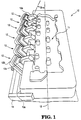
- Fig. 1 is a perspective view of one preferred core box portion for use in the invention to provide a one-piece water jacket core.
- the core box portion 10, shown in Fig. 1 includes a cavity forming portion 11 adapted to form a lower portion of a one-piece water jacket core.
- a plurality of movable members 12 are pivotally carried by the core box portion 10.
- Each of the movable members 12 includes a portion 12a adapted to form a water jacket exhaust port and to be pivoted after assembly of the core box, as shown in the other drawings and described below, to a position within the core box cavity forming one of the water jacket exhaust ports in the one-piece water jacket core.
- the plurality of movable members 12 are preferably pivotally mounted in a line along one side 10a of core box portion 10.
- the water jacket exhaust port-forming portion 12a of each of the plurality of movable members 12 is adapted for entry into one of a plurality of openings 16 (Fig. 2) formed at the interface between the core box portion 10 and a second core box portion 20 that includes a second cavity 21 adapted to form the upper portion of the one-piece water jacket core when the second core box portion is assembled on the first core box portion 10.
- Each of the movable members 12 further includes a seal-forming portion 12b adapted to be seated at and close the opening 16 formed at the interface between the first and second core box portions.
- each seal-forming portion 12b carries an O-ring seal and can be adapted to seal an opening against pressures up to about 0,689 N/mm 2 (100 psi).
- each of the movable members 12 is mounted to the core box portion 10 so that it pivots on an axis that lies at 75° with respect to the centerline of the internal combustion engine, which is indicated in Fig. 1 by dashed line 13.
- each of the plurality of movable members 12 is pivotally mounted at one side 10a of the core box portion 10 and is operated by a common actuator 14, as more fully described below.
- Figs. 2-9 are simplified diagrammatic illustrations of the method and apparatus of this invention.
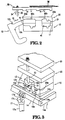
- Fig. 2 is a simplified cross-sectional view of the elements of a preferred system of the invention which, in the preferred method of the invention, operate in a sequence shown in Figs. 4-9. While the movable members 12, shown in Figs. 2 and 4-9, are illustrated as separate and detached from core box portion 10, it should be understood that in preferable systems of the invention the plurality of movable members 12 will be pivotally connected with the first core box portion 10, as shown in Figs. 1 and 3.
- the manner in which the plurality of movable members 12 are pivotally attached to the first core box portion 10, including any angles their pivotal axes may have with respect to the centerline of the one-piece water jacket core or the cylinder head is determined by the cylinder head and internal combustion engine design.
- One advantage of the invention is that ports can be formed in the one-piece water jacket core lying at variable angles with respect to the central axis of the one-piece water jacket core, and the method and apparatus of the invention permits increased flexibility in the design of internal combustion engines.
- the means of this invention providing a one-piece water jacket core for an internal combustion engine includes a first core box portion 10 and a second core box portion 20, which, upon assembly, form a one-piece water jacket core.
- the first core box portion 10 includes a first cavity 11 adapted to form the lower portion of the one-piece water jacket core and the second core box portion 20 includes a second cavity 21 adapted to form an upper portion of the one-piece water jacket core.
- a plurality of movable members 12, one of which is shown in cross-section in Fig. 2, are mounted to pivot as shown by the movement indicating arrow 19. As noted above and shown in Figs.
- the plurality of movable members are preferably pivotally carried by one of the core box portions, preferably by the lower first core box portion 10.
- Each of the movable members 12 includes a portion 12a adapted to form an exhaust port in the one-piece water jacket core when pivoted into the cavity 40 that is formed after assembly of the first and second core box portions, 10 and 20 respectively.
- the plurality of movable members are pivotally mounted in a line along one side 10a of the core box portion 10, and each of the water jacket exhaust port-forming portions 12a of the movable members is adapted for entry into one of a plurality of openings 16 formed at the interface between the first core box portion 10 and the second core box portion 20 when assembled.
- each of the movable members 12 includes a seal-forming portion 12b which is adapted to be seated at and close the opening 16 formed at the interface of the first and second core box portions 10 and 20, respectively.
- the movable members 12 may be formed with a groove in the surface interfacing the first and second core box portions 10 and 20, respectively, and may be provided with an O-ring, or elastomeric gasket, to provide a seal around the opening 16 to prevent the escape of core-forming materials when the cavity 40 formed by the core box portions 10 and 20 is filled.
- each of the plurality of movable members 12 may be carried by a core box portion in any convenient manner dictated by the design of the one-piece water jacket core to be manufactured.
- One such method is indicated in Fig. 3, which for convenience, shows only one of the plurality of movable members 12.
- each of the plurality of movable members 12 is pivotally mounted on one side 10a of the first core box portion 10 by an axle 10b extending between a pair of bosses 10c formed on one side 10a of the core box 10.
- Each of the plurality of movable members 12 is provided with a pair of bosses 12c on the seat forming portion 12b.
- the pair of bosses 12c rotatably carry an axle 15 and a driving rod 16 which is pivotally mounted to the actuator 14 which is common to and drives the plurality of movable members 12.
- the common actuator 14 may be driven by a hydraulic cylinder 17.
- the common actuator 14 may include lever portions 14a at each end, each of which may be rotatably carried by the first core portion 10.
- Preferred systems of the invention are adapted to use a cold-cure process and include means for locking the movable members 12 in their seated positions.
- Figs. 2 and 4-9 illustrate one such preferred method and apparatus.
- the upper second core box portion 20 can include a plurality of gas-receiving bores 20b in its upper surface 20c.
- the gas-receiving bores 20b extend from the upper surface 20c into the second cavity forming portion 21 of the second core-forming portion 20.
- a gas distributor 30 is adapted to be seated on the upper surface 20c of the upper core-forming portion 20.
- the gas distributor 30 includes a plurality of gas injectors 31, which are connected with a gas distributing system 32 to provide a curing gas to the cavity 40 formed by the first and second core members 10 and 20 as part of the cold-cure process.
- the gas distributor 30 also includes a plurality of locking elements 33 positioned to engage the plurality of movable members 12 in their pivoted and seated positions when the gas distributor is seated on the second core-forming portion, as shown in Fig. 3.
- the gas distributor 30 is moved downwardly, as indicated by arrow 34 of Fig. 2, so that the locking elements 33 bear against the back surface of the seat forming portion 12b of the movable members 12 to prevent the seat forming portions 12b from moving away from the sides 10a and 20a as the cavity 40 formed by core-forming portions 10 and 20 is filled with core-forming material.
- the pressures used to inject core-forming material into the internal cavities generally lies in the range of 0,345-0,689 N/mm 2 (50-100 psi), typically about 0,448 N/mm 2 (65 psi), and the locking elements must be able to withstand forces on the order of several hundred kg (pounds), depending upon the design of the water jacket core and the area of the movable members exposed to the filling pressure for the cavity.
- steel rods having a diameter on the order of 9,525 to 12,7 mm (3/8 to 1/2 inch) can provide adequate rigidity to prevent the unseating of the movable elements with core filling pressures on the order of 0,448 N/mm 2 (65 psi).
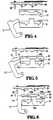
- Figs. 4-9 illustrate a preferred method of the invention.
- a first core-forming portion 10 is provided.
- the first core-forming portion includes a cavity portion 11 for the lower portion of a one-piece water jacket core.
- a second core-forming portion 20 is provided including a second cavity 21 for the upper portion of the one-piece water jacket core.
- the first and second core-forming portions are assembled by seating the second core-forming portion on the first core-forming portion to provide a core box enclosure with a cavity 40 formed by cavity portions 11 and 21 to form a one-piece water jacket core.
- the core box enclosure formed by first and second core box portions 10 and 20, respectively, has a plurality of openings 16 into the cavity 40.
- the plurality of water jacket port-forming members 12 are pivoted as indicated by the arrow 19 of Fig. 5 so that the water jacket port-forming portions 12a are moved through the plurality of openings 16 to within the cavity 40 of the core box enclosure and the seal-forming portions 12b close the opening 16, as shown in Fig. 6.
- the preferred method of the invention includes a cold-cure in which the upper (second) core box portion 20 is provided with a plurality of passageways 20b leading into the cavity 40 and through which a curing gas is provided into the cavity after filling to cure the core-forming material.
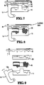
- a gas distributor 30 is provided including a plurality of gas injectors 31 and a plurality of member locking elements 33. As shown in Fig. 6, the gas distributor is moved downwardly, as indicated by the arrow 34, and is positioned on the upper surface 20c of core box portion 20 after the plurality of movable water jacket port-forming members 20 have been pivoted into the position shown in Fig. 6.
- the gas distributor 30 is thus positioned on the upper surface of core-forming portion 20 with its plurality of gas injectors 31 mating the plurality of gas-receiving bores 20b and the plurality of member locking elements 33 engaging and holding the movable members 12 seated against the sides of core-forming portions 10 and 20.
- the cavity 40 is filled with a core-forming material including a curing resin which is adapted to be cured by a curing gas in a cold-cure process.
- a curing gas is applied to the gas distributor and injected into the cavity through the gas injectors 31 of gas distributor 30, as indicated in Fig. 8.
- the gas distributor 30 is moved upwardly and away from the core assembly, the plurality of movable members 12 are pivoted outwardly to remove the water jacket exhaust port-forming portions 12a from the openings 16 formed by core-forming portions 10 and 20, the second core-forming portion 20 is disassembled from the first core-forming portion 10 by moving it upwardly, and the one-piece water jacket core 50 is removed from core-forming portion 10, all as generally indicated in Fig. 9.
- the resulting one-piece water jacket core need only be inspected for core fins and may then be processed in the further manufacture of a cylinder head, as, for example, disclosed by U.S. patent No. 5,119,881 granted June 9, 1992.
- One of the advantages of the invention and its pivotal insertion of port-forming portions into a one-piece water jacket core is that the draft required on the exhaust port-forming portion of the movable members can be substantially reduced over corresponding elements that might otherwise be moved in a straight line.
- a port-forming portion adapted for straight line insertion into a core-forming cavity may have sides with a draft as large as 1°
- the formation of ports by pivoting or rotational insertion of the port-forming portion into the core-forming cavity can reduce the effective draft to as little as about 1/8°.
- the preferred method does not require heat cure of the core-forming material and as a result, the one-piece water jacket cores are not subject to warping and are dimensionally stable and predictable, thereby improving the dimensional integrity of the resulting castings. Since the core box portions are not exposed to large temperature variations, they are less expensive to build and maintain. Elimination of the adhesive pasting operation improves the reliability of the castings that result from the one-piece water jacket core. The mismatches in the assembly of the two-piece water jacket sores that were frequently encountered are eliminated, which increases in the reliability of the resulting castings.
- the invention eliminates the assembly fixtures formally needed in the manufacture of the water jacket core, reduces labor from 4-5 men to substantially one man, and reduces the foundry floor space requirements by 883 m 2 (9,500 square feet), by eliminating a core pasting assembly station and adhesive curing oven. Furthermore, with the invention, the manufacture of the water jacket core is no longer the operation which paces the manufacture of core assemblies for the casting of cylinder heads.
Landscapes
- Engineering & Computer Science (AREA)
- Mechanical Engineering (AREA)
- Molds, Cores, And Manufacturing Methods Thereof (AREA)
- Physical Or Chemical Processes And Apparatus (AREA)
- Cylinder Crankcases Of Internal Combustion Engines (AREA)
- Moulds For Moulding Plastics Or The Like (AREA)
- Heating, Cooling, Or Curing Plastics Or The Like In General (AREA)
Claims (12)
- Vorrichtung zur Herstellung eines einteiligen Wassermantelkerns für einen Verbrennungsmotor, mit:einem ersten Kernkastenabschnitt (10) und einem zweiten Kernkastenabschnitt (20), die für eine Montage ausgelegt sind, um einen einteiligen Wassermantelkern auszubilden;wobei der erste Kernkastenabschnitt (10) einen ersten Hohlraum (11) aufweist, der vorgesehen ist, um einen unteren Abschnitt des einteiligen Wassermantelkerns auszubilden, und wobei der zweite Kernkastenabschnitt (20) einen zweiten Hohlraum (21) aufweist, der vorgesehen ist, um einen oberen Abschnitt des einteiligen Wassermantelkerns auszubilden; undeiner Mehrzahl von bewegbaren Teilen (12), die durch einen der Kernkastenabschnitte drehbar gehalten werden, wobei jedes der bewegbaren Teile (12) vorgesehen ist, um eine Auslaßöffnung im einteiligen Wassermantelkern auszubilden und um nach der Montage des ersten und zweiten Kernkastenabschnitts (10, 20) in eine Lage gedreht zu werden, in der eine der Wassermantel-Auslaßöffnungen im einteiligen Wassermantelkern ausgebildet wird.
- Vorrichtung nach Anspruch 1, wobei die Mehrzahl an bewegbaren Teilen (12) in einer Reihe längs einer Seite eines Kernkastenabschnitts drehbar befestigt sind und wobei jedes Teil der Mehrzahl an bewegbaren Teilen (12) einen Abschnitt (12a) zum Ausbilden einer Wassermantel-Auslaßöffnung enthält, der zum Eintritt in eine Öffnung einer Mehrzahl von Öffnungen (16) vorgesehen ist, die im montierten Zustand an der Schnittstelle zwischen dem ersten Kernkastenabschnitt (10) und dem zweiten Kernkastenabschnitt (20) zum Ausbilden einer Wassermantel-Auslaßöffung ausgebildet sind, und ferner einen Abschnitt (12b) zum Ausbilden einer Abdichtung enthält, der vorgesehen ist, um an der einen Öffnung (16) anzuliegen und diese zu verschließen, die an der Schnittstelle zwischen den ersten und zweiten Kernkastenabschnitten (10, 20) ausgebildet ist.
- Vorrichtung nach Anspruch 2, wobei jedes der bewegbaren Teile (12) befestigt ist, um sich auf einer Achse zu drehen, die 75° bezüglich der Mittellinie des Verbrennungsmotors vorliegt.
- Vorrichtung nach Anspruch 2, wobei die Mehrzahl an bewegbaren Teilen (12) durch den ersten Kernkastenabschnitt (10) gehalten wird.
- Vorrichtung nach Anspruch 1, wobei der zweite Kernkastenabschnitt (20) eine Mehrzahl an Durchgängen aufweist, die vorgesehen sind, um ein Aushärtgas zum ersten Hohlraum zu leiten.
- Vorrichtung nach Anspruch 4, wobei der zweite Kernkastenabschnitt (20) an seiner oberen Fläche (20c) eine Mehrzahl an gasaufnehmenden Bohrungen (20b) enthält, wobei die Bohrungen (20b) in den zweiten Hohlraum (21) münden und wobei die Vorrichtung ferner einen Gasverteiler (30) enthält, der vorgesehen ist, um auf der oberen Fläche (20c) des zweiten Kernkastenabschnitts (20) aufgesetzt zu werden, wobei der Gasverteiler (30) eine Mehrzahl von Gasinjektoren (31) aufweist, die auf die Mehrzahl an gasaufnehmenden Bohrungen (20b) des zweiten Kernabschnitts (20) abgestimmt sind, wenn sie abgesetzt sind, und ferner eine Mehrzahl von Verriegelungselementen (33) aufweist, die positioniert sind, um in die durch den ersten Kernkastenabschnitt (10) gehaltene Mehrzahl an bewegbaren Teilen (12) einzugreifen und dabei die Abschnitte (12b) der Mehrzahl der bewegbaren Teile (12) zum Ausbilden einer Abdichtung in ihren Aufnahmelagen zu verriegeln, in denen die Öffnungen (16) geschlossen sind.
- Vorrichtung nach Anspruch 4, wobei jedes Teil der Mehrzahl der bewegbaren Teile (12) mit einem gemeinsamen Stellglied (14) verbunden ist, wobei das gemeinsame Stellglied (14) mit einer Antriebseinrichtung verbunden ist, um das gemeinsame Stellglied (14) zu bewegen und die Mehrzahl an bewegbaren Teilen (12) in die Mehrzahl der Öffnungen (16) zu drehen.
- Vorrichtung nach Anspruch 7, wobei jedes Teil der Mehrzahl an bewegbaren Teilen (12) drehbar an einer Seite (10a) des ersten Kernkastenabschnitts (10) befestigt und mit einem Paar an Vorsprüngen (12c) auf dem sitzausbildenden Abschnitt (12b) versehen ist, wobei das Paar an Vorsprüngen (12c) zwischen sich eine Achse (15) hält, und wobei das gemeinsame Stellglied (14) eine Stange aufweist, die parallel und benachbart zur einen Seite (10a) des ersten Kernkastenabschnitts (10) liegt, wobei die Stange des gemeinsamen Stellglieds eine Mehrzahl an Bauteilantriebstäben drehbar hält, wobei jeder der Bauteilantriebstäbe mit einer Achse von einem der bewegbaren Teile (12) derart verbunden ist, daß eine Betätigung der Antriebseinrichtung die Stange des gemeinsamen Stellglieds, die Mehrzahl an Antriebstäben und die Mehrzahl an bewegbaren Teilen (12) antreibt.
- Vorrichtung nach Anspruch 8, wobei das gemeinsame Stellglied (14) drehbar durch den ersten Kernkastenabschnitt (10) gehalten wird, und wobei die Antriebseinrichtung ein Hydraulikzylinder (17) ist, dessen Zylinderabschnitt (17a) mit dem ersten Kernkastenabschnitt (10) und dessen Kolben (17b) mit der Stange des gemeinsamen Stellglieds verbunden ist.
- Verfahren zur Herstellung eines einteiligen Wassermantelkerns, mit den Schritten:Vorsehen eines ersten kernausbildenden Abschnitts (10) eines Kernkastens für einen einteiligen Wassermantelkern;Vorsehen eines zweiten kernausbildenden Abschnitts (20) des Kernkastens für den einteiligen Wassermantelkern;Zusammenfügen des ersten und zweiten kernausbildenden Abschnitts (10, 20), um ein Kernkastengehäuse mit einem Hohlraum (11, 21) zu schaffen, um einen einteiligen Wassermantelkern auszubilden, wobei das Kernkastengehäuse eine Mehrzahl an Öffnungen (16) in den Hohlraum (11, 21) aufweist, welcher durch einen oder mehrere der kernausbildenden Abschnitte (10, 20) ausgebildet wird;Vorsehen einer Mehrzahl von drehbaren Teilen (12) zum Ausbilden einer Wassermantelöffnung, die durch einen der kernausbildenden Abschnitte gehalten werden, wobei jedes der drehbaren Teile (12) zum Ausbilden einer Wassermantelöffnung einer der Öffnungen (16) benachbart ist;Drehen der Mehrzahl an Teilen (12) zum Ausbilden der Wassermantelöffnung durch die Mehrzahl an Öffnungen (16), wodurch innerhalb des Hohlraums (11, 21) des Kernkastengehäuses Abschnitte der Teile (12) zum Ausbilden der Wassermantelöffnungen vorliegen und die Mehrzahl an Öffnungen (16) geschlossen werden;Füllen des Kernkastengehäuses mit einem aushärtbaren, kernausbildenden Material;Aushärten des kernausbildenden Materials;Drehen der Mehrzahl an Teilen (12) zum Ausbilden der Wassermantelöffnung, um diese aus dem Hohlraum (11, 21) des Kernkastengehäuses zu entfernen; undDemontieren des ersten und zweiten Kernkastenabschnitts (10, 20) und Entfernen des einteiligen Wassermantelkerns.
- Verfahren nach Anspruch 10, welches ferner einen Kaltkern vorsieht, mit den weiteren Schritten:Ausbilden des Kernkastengehäuses mit einer Mehrzahl an Durchgängen (20b) zum Hohlraum (11, 21); undEinführen eines Aushärtgases in die Mehrzahl an Durchgängen (20b) und in den Hohlraum (11, 21), nachdem das kernausbildende Gehäuse mit dem aushärtbaren, kernausbildenden Material gefüllt ist, um das kernausbildende Material auszuhärten.
- Verfahren nach Anspruch 10, mit den weiteren Schritten:Ausbilden des zweiten kernkastenausbildenden Abschnitts (20) mit einer Mehrzahl von gasaufnehmenden Bohrungen (20b) zwischen einer oberen Fläche (20a) und dem Hohlraum (11, 21);Vorsehen eines Gasverteilers (30), der eine Mehrzahl an Gasinjektoren (31) enthält, die auf die Mehrzahl der gasaufnehmenden Bohrungen (20b) abgestimmt sind, und der ferner eine Mehrzahl von Bauteilverriegelungselementen (33) enthält;Positionieren des Gasverteilers (30) auf dem zweiten kernausbildenden Abschnitt (20) nachdem die Mehrzahl der Teile (12) zum Ausbilden der Wassermantelöffnungen durch die Mehrzahl der Öffnungen (16) gedreht wurde, Abstimmen der Gasinjektoren (31) auf die Mehrzahl an gasaufnehmenden Bohrungen (20b) und Verriegeln der Mehrzahl der Teile (12) zum Ausbilden der Wassermantelöffnungen an der Mehrzahl der Öffnungen (16) mittels der Mehrzahl an Bauteilverriegelungselementen (33); undEinführen eines Aushärtgases in den Hohlraum (11, 21) nachdem das kernausbildende Gehäuses mit dem aushärtbaren, kernausbildenden Material gefüllt ist, um das kernausbildende Material auszuhärten;Entfernen des Gasverteilers (30); undDrehen und Entfernen der Mehrzahl an Teilen (12) zum Ausbilden der Wassermantelöffnungen vom Inneren des Kernkastengehäuses, nachdem das kernausbildende Material ausgehärtet ist, und Demontage des ersten und zweiten Kernkastenabschnitts (10, 20), um den einteiligen Wassermantelkern zu entfernen.
Applications Claiming Priority (2)
| Application Number | Priority Date | Filing Date | Title |
|---|---|---|---|
| US07/913,256 US5230378A (en) | 1992-07-14 | 1992-07-14 | Method and apparatus for manufacturing one-piece water jacket cores |
| US913256 | 1992-07-14 |
Publications (2)
| Publication Number | Publication Date |
|---|---|
| EP0578864A1 EP0578864A1 (de) | 1994-01-19 |
| EP0578864B1 true EP0578864B1 (de) | 1997-01-08 |
Family
ID=25433095
Family Applications (1)
| Application Number | Title | Priority Date | Filing Date |
|---|---|---|---|
| EP92117944A Expired - Lifetime EP0578864B1 (de) | 1992-07-14 | 1992-10-20 | Verfahren und Vorrichtung zur Herstellung von einteiligen Wassermantelkernen |
Country Status (7)
| Country | Link |
|---|---|
| US (1) | US5230378A (de) |
| EP (1) | EP0578864B1 (de) |
| AT (1) | ATE147300T1 (de) |
| CA (1) | CA2080318C (de) |
| DE (1) | DE69216598T2 (de) |
| ES (1) | ES2098412T3 (de) |
| MX (1) | MX9206854A (de) |
Families Citing this family (4)
| Publication number | Priority date | Publication date | Assignee | Title |
|---|---|---|---|---|
| DE102005001023A1 (de) * | 2005-01-07 | 2006-07-20 | Fev Motorentechnik Gmbh | Zylinderkopfkühlmantel |
| RU2347642C1 (ru) * | 2007-06-06 | 2009-02-27 | Открытое акционерное общество "КАМАЗ-Металлургия" | Стержневой ящик для формовки стержней с поднутрениями |
| JP5136203B2 (ja) * | 2008-05-20 | 2013-02-06 | 京セラドキュメントソリューションズ株式会社 | 画像形成システム |
| CN103752768B (zh) * | 2014-01-27 | 2015-07-01 | 苏州明志科技有限公司 | 用于同时制备水套芯和油道芯的垂直与水平复合式芯盒 |
Family Cites Families (7)
| Publication number | Priority date | Publication date | Assignee | Title |
|---|---|---|---|---|
| US2901792A (en) * | 1958-04-28 | 1959-09-01 | Int Harvester Co | Core box with sectional mold construction |
| US3060534A (en) * | 1960-01-06 | 1962-10-30 | Jean A Enzenbacher | Core setting method and apparatus |
| JPS4830210A (de) * | 1971-08-23 | 1973-04-21 | ||
| US4248288A (en) * | 1979-08-20 | 1981-02-03 | Anatol Michelson | Fusion process for forming shell cores |
| JPS58100941A (ja) * | 1981-12-12 | 1983-06-15 | Kubota Ltd | ガス硬化式鋳型造型用金型装置 |
| JPS59118244A (ja) * | 1982-12-24 | 1984-07-07 | Toyota Motor Corp | ガス硬化式鋳型造型法および装置 |
| US4830082A (en) * | 1986-12-03 | 1989-05-16 | Roberts Corporation | Machine and method for making molds using an activating gas |
-
1992
- 1992-07-14 US US07/913,256 patent/US5230378A/en not_active Expired - Lifetime
- 1992-10-09 CA CA002080318A patent/CA2080318C/en not_active Expired - Fee Related
- 1992-10-20 AT AT92117944T patent/ATE147300T1/de not_active IP Right Cessation
- 1992-10-20 ES ES92117944T patent/ES2098412T3/es not_active Expired - Lifetime
- 1992-10-20 EP EP92117944A patent/EP0578864B1/de not_active Expired - Lifetime
- 1992-10-20 DE DE69216598T patent/DE69216598T2/de not_active Expired - Fee Related
- 1992-11-27 MX MX9206854A patent/MX9206854A/es not_active IP Right Cessation
Also Published As
| Publication number | Publication date |
|---|---|
| US5230378A (en) | 1993-07-27 |
| CA2080318C (en) | 2004-08-03 |
| ATE147300T1 (de) | 1997-01-15 |
| DE69216598D1 (de) | 1997-02-20 |
| EP0578864A1 (de) | 1994-01-19 |
| ES2098412T3 (es) | 1997-05-01 |
| MX9206854A (es) | 1994-01-31 |
| DE69216598T2 (de) | 1997-04-30 |
| CA2080318A1 (en) | 1994-01-15 |
Similar Documents
| Publication | Publication Date | Title |
|---|---|---|
| CA2017499C (en) | Cylinder head casting apparatus and method | |
| US6615901B2 (en) | Casting of engine blocks | |
| CN100439008C (zh) | 铸型组装设备和方法 | |
| MXPA05002557A (es) | Procedimiento de fundicion, particularmente para cabeza de cilindros de un motor. | |
| US5251683A (en) | Method of making a cylinder head or other article with cast in-situ ceramic tubes | |
| JPS63149124A (ja) | 射出成形装置 | |
| CN106168181B (zh) | 用于发动机的复合汽缸体 | |
| US6527039B2 (en) | Casting of engine blocks | |
| US3678987A (en) | Elastomeric mold lining for making wax replica of complex part to be cast | |
| CA2382968C (en) | Casting of engine blocks | |
| GB2374567A (en) | Ceramic core having locator elements moulded thereon | |
| CN110014125B (zh) | 柴油机缸体包芯工艺砂芯组合的铸造结构 | |
| KR20090092765A (ko) | 피스톤엔진용 밸브 시트 인서어트 | |
| US20020185242A1 (en) | Casting of engine blocks | |
| US5230378A (en) | Method and apparatus for manufacturing one-piece water jacket cores | |
| US6435259B1 (en) | Core assembly method for cylinder head castings | |
| US5445210A (en) | Casting core for forming cast-in intersecting push rod passages and oil gallery within a cylinder block | |
| MXPA03000559A (es) | Equipo para moldear partes de fundicion con medios mejorados para colocar nucleos de arena y metodo de colocacion relacionado. | |
| US4766944A (en) | Process for casting fiber-reinforced metal body | |
| EP1218126B1 (de) | Verfahren und vorrichtung zum giessen | |
| JPH037465B2 (de) | ||
| KR100349616B1 (ko) | 진공중력주조 | |
| RU2146183C1 (ru) | Отливка блока цилиндров двигателя внутреннего сгорания и способ ее получения | |
| CN111745794A (zh) | 盾构隧道的箱涵模具 | |
| KR102562914B1 (ko) | 다이캐스팅을 이용한 차량용 스로틀바디의 제조방법 및 제조장치 |
Legal Events
| Date | Code | Title | Description |
|---|---|---|---|
| PUAI | Public reference made under article 153(3) epc to a published international application that has entered the european phase |
Free format text: ORIGINAL CODE: 0009012 |
|
| AK | Designated contracting states |
Kind code of ref document: A1 Designated state(s): AT BE DE ES FR GB IT NL SE |
|
| 17P | Request for examination filed |
Effective date: 19940621 |
|
| 17Q | First examination report despatched |
Effective date: 19950808 |
|
| GRAH | Despatch of communication of intention to grant a patent |
Free format text: ORIGINAL CODE: EPIDOS IGRA |
|
| GRAH | Despatch of communication of intention to grant a patent |
Free format text: ORIGINAL CODE: EPIDOS IGRA |
|
| GRAA | (expected) grant |
Free format text: ORIGINAL CODE: 0009210 |
|
| AK | Designated contracting states |
Kind code of ref document: B1 Designated state(s): AT BE DE ES FR GB IT NL SE |
|
| REF | Corresponds to: |
Ref document number: 147300 Country of ref document: AT Date of ref document: 19970115 Kind code of ref document: T |
|
| ITF | It: translation for a ep patent filed | ||
| REF | Corresponds to: |
Ref document number: 69216598 Country of ref document: DE Date of ref document: 19970220 |
|
| ET | Fr: translation filed | ||
| REG | Reference to a national code |
Ref country code: ES Ref legal event code: FG2A Ref document number: 2098412 Country of ref document: ES Kind code of ref document: T3 |
|
| PLBE | No opposition filed within time limit |
Free format text: ORIGINAL CODE: 0009261 |
|
| STAA | Information on the status of an ep patent application or granted ep patent |
Free format text: STATUS: NO OPPOSITION FILED WITHIN TIME LIMIT |
|
| 26N | No opposition filed | ||
| PGFP | Annual fee paid to national office [announced via postgrant information from national office to epo] |
Ref country code: GB Payment date: 20010914 Year of fee payment: 10 |
|
| REG | Reference to a national code |
Ref country code: GB Ref legal event code: IF02 |
|
| REG | Reference to a national code |
Ref country code: GB Ref legal event code: 732E |
|
| REG | Reference to a national code |
Ref country code: FR Ref legal event code: CD Ref country code: FR Ref legal event code: CA |
|
| REG | Reference to a national code |
Ref country code: FR Ref legal event code: TP |
|
| PG25 | Lapsed in a contracting state [announced via postgrant information from national office to epo] |
Ref country code: GB Free format text: LAPSE BECAUSE OF NON-PAYMENT OF DUE FEES Effective date: 20021020 |
|
| GBPC | Gb: european patent ceased through non-payment of renewal fee |
Effective date: 20021020 |
|
| PGFP | Annual fee paid to national office [announced via postgrant information from national office to epo] |
Ref country code: AT Payment date: 20050914 Year of fee payment: 14 |
|
| PGFP | Annual fee paid to national office [announced via postgrant information from national office to epo] |
Ref country code: NL Payment date: 20050916 Year of fee payment: 14 |
|
| PGFP | Annual fee paid to national office [announced via postgrant information from national office to epo] |
Ref country code: SE Payment date: 20051004 Year of fee payment: 14 |
|
| PGFP | Annual fee paid to national office [announced via postgrant information from national office to epo] |
Ref country code: FR Payment date: 20051006 Year of fee payment: 14 |
|
| PGFP | Annual fee paid to national office [announced via postgrant information from national office to epo] |
Ref country code: ES Payment date: 20051014 Year of fee payment: 14 |
|
| PGFP | Annual fee paid to national office [announced via postgrant information from national office to epo] |
Ref country code: DE Payment date: 20051031 Year of fee payment: 14 |
|
| PGFP | Annual fee paid to national office [announced via postgrant information from national office to epo] |
Ref country code: BE Payment date: 20051104 Year of fee payment: 14 |
|
| PG25 | Lapsed in a contracting state [announced via postgrant information from national office to epo] |
Ref country code: AT Free format text: LAPSE BECAUSE OF NON-PAYMENT OF DUE FEES Effective date: 20061020 |
|
| PG25 | Lapsed in a contracting state [announced via postgrant information from national office to epo] |
Ref country code: SE Free format text: LAPSE BECAUSE OF NON-PAYMENT OF DUE FEES Effective date: 20061021 |
|
| PGFP | Annual fee paid to national office [announced via postgrant information from national office to epo] |
Ref country code: IT Payment date: 20061031 Year of fee payment: 15 |
|
| PG25 | Lapsed in a contracting state [announced via postgrant information from national office to epo] |
Ref country code: NL Free format text: LAPSE BECAUSE OF NON-PAYMENT OF DUE FEES Effective date: 20070501 Ref country code: DE Free format text: LAPSE BECAUSE OF NON-PAYMENT OF DUE FEES Effective date: 20070501 |
|
| EUG | Se: european patent has lapsed | ||
| NLV4 | Nl: lapsed or anulled due to non-payment of the annual fee |
Effective date: 20070501 |
|
| REG | Reference to a national code |
Ref country code: FR Ref legal event code: ST Effective date: 20070629 |
|
| BERE | Be: lapsed |
Owner name: *NAVISTAR INTERNATIONAL TRANSPORTATION CORP. Effective date: 20061031 |
|
| REG | Reference to a national code |
Ref country code: ES Ref legal event code: FD2A Effective date: 20061021 |
|
| PG25 | Lapsed in a contracting state [announced via postgrant information from national office to epo] |
Ref country code: FR Free format text: LAPSE BECAUSE OF NON-PAYMENT OF DUE FEES Effective date: 20061031 Ref country code: ES Free format text: LAPSE BECAUSE OF NON-PAYMENT OF DUE FEES Effective date: 20061021 |
|
| PG25 | Lapsed in a contracting state [announced via postgrant information from national office to epo] |
Ref country code: IT Free format text: LAPSE BECAUSE OF NON-PAYMENT OF DUE FEES Effective date: 20071020 Ref country code: BE Free format text: LAPSE BECAUSE OF FAILURE TO SUBMIT A TRANSLATION OF THE DESCRIPTION OR TO PAY THE FEE WITHIN THE PRESCRIBED TIME-LIMIT Effective date: 20061031 |