EP0578908A2 - Appareil de diagnostique médical utilisant la détection de la direction du regard - Google Patents
Appareil de diagnostique médical utilisant la détection de la direction du regard Download PDFInfo
- Publication number
- EP0578908A2 EP0578908A2 EP93100563A EP93100563A EP0578908A2 EP 0578908 A2 EP0578908 A2 EP 0578908A2 EP 93100563 A EP93100563 A EP 93100563A EP 93100563 A EP93100563 A EP 93100563A EP 0578908 A2 EP0578908 A2 EP 0578908A2
- Authority
- EP
- European Patent Office
- Prior art keywords
- movement
- subject
- output
- sight
- head
- Prior art date
- Legal status (The legal status is an assumption and is not a legal conclusion. Google has not performed a legal analysis and makes no representation as to the accuracy of the status listed.)
- Granted
Links
Images


Classifications
-
- A—HUMAN NECESSITIES
- A61—MEDICAL OR VETERINARY SCIENCE; HYGIENE
- A61B—DIAGNOSIS; SURGERY; IDENTIFICATION
- A61B5/00—Measuring for diagnostic purposes; Identification of persons
- A61B5/103—Measuring devices for testing the shape, pattern, colour, size or movement of the body or parts thereof, for diagnostic purposes
- A61B5/11—Measuring movement of the entire body or parts thereof, e.g. head or hand tremor or mobility of a limb
-
- A—HUMAN NECESSITIES
- A61—MEDICAL OR VETERINARY SCIENCE; HYGIENE
- A61B—DIAGNOSIS; SURGERY; IDENTIFICATION
- A61B3/00—Apparatus for testing the eyes; Instruments for examining the eyes
- A61B3/10—Objective types, i.e. instruments for examining the eyes independent of the patients' perceptions or reactions
- A61B3/113—Objective types, i.e. instruments for examining the eyes independent of the patients' perceptions or reactions for determining or recording eye movement
-
- A—HUMAN NECESSITIES
- A61—MEDICAL OR VETERINARY SCIENCE; HYGIENE
- A61B—DIAGNOSIS; SURGERY; IDENTIFICATION
- A61B5/00—Measuring for diagnostic purposes; Identification of persons
- A61B5/40—Detecting, measuring or recording for evaluating the nervous system
- A61B5/4076—Diagnosing or monitoring particular conditions of the nervous system
- A61B5/4088—Diagnosing of monitoring cognitive diseases, e.g. Alzheimer, prion diseases or dementia
-
- G—PHYSICS
- G16—INFORMATION AND COMMUNICATION TECHNOLOGY [ICT] SPECIALLY ADAPTED FOR SPECIFIC APPLICATION FIELDS
- G16H—HEALTHCARE INFORMATICS, i.e. INFORMATION AND COMMUNICATION TECHNOLOGY [ICT] SPECIALLY ADAPTED FOR THE HANDLING OR PROCESSING OF MEDICAL OR HEALTHCARE DATA
- G16H15/00—ICT specially adapted for medical reports, e.g. generation or transmission thereof
-
- A—HUMAN NECESSITIES
- A61—MEDICAL OR VETERINARY SCIENCE; HYGIENE
- A61B—DIAGNOSIS; SURGERY; IDENTIFICATION
- A61B5/00—Measuring for diagnostic purposes; Identification of persons
- A61B5/68—Arrangements of detecting, measuring or recording means, e.g. sensors, in relation to patient
- A61B5/6801—Arrangements of detecting, measuring or recording means, e.g. sensors, in relation to patient specially adapted to be attached to or worn on the body surface
- A61B5/6802—Sensor mounted on worn items
- A61B5/6803—Head-worn items, e.g. helmets, masks, headphones or goggles
-
- G—PHYSICS
- G16—INFORMATION AND COMMUNICATION TECHNOLOGY [ICT] SPECIALLY ADAPTED FOR SPECIFIC APPLICATION FIELDS
- G16H—HEALTHCARE INFORMATICS, i.e. INFORMATION AND COMMUNICATION TECHNOLOGY [ICT] SPECIALLY ADAPTED FOR THE HANDLING OR PROCESSING OF MEDICAL OR HEALTHCARE DATA
- G16H40/00—ICT specially adapted for the management or administration of healthcare resources or facilities; ICT specially adapted for the management or operation of medical equipment or devices
- G16H40/60—ICT specially adapted for the management or administration of healthcare resources or facilities; ICT specially adapted for the management or operation of medical equipment or devices for the operation of medical equipment or devices
- G16H40/63—ICT specially adapted for the management or administration of healthcare resources or facilities; ICT specially adapted for the management or operation of medical equipment or devices for the operation of medical equipment or devices for local operation
Definitions
- the present invention relates to a medical diagnostic apparatus utilizing line-of-sight detection, and more specifically, it relates to a medical diagnostic apparatus which enables diagnoses of diseases related to brain function such as dementia by detecting line-of-sight of a subject.
- the number of patients suffering from Alzheimer's disease is estimated to be four million in the United States and about a million in Japan.
- senile dementia such as cerebrovascular disease popular among Japanese
- the cause of Alzheimer's disease is not known, and much effort has made to find the cause so as to enable early diagnosis and early medical treatment.
- Hachinski's ischemic score has been proposed as a method of discriminating these two diseases. According to this ischemic score, a point is given dependent on whether or not the patient has an anamnesis of apoplexy, cerebral infraction or the like and if the points exceeds a prescribed number, it is determined as the cerebrovascular disease, and otherwise it is determined to be Alzheimer's disease. However, discrimination is still difficult by this method if the patient has no such anamnesis.
- an object of the present invention is to provide a medical diagnostic apparatus which facilitates diagnosis of diseases related to brain function by noting movement of one's line-of-sight implemented by the eye movement of the subject.
- eye movement of a subject is detected while a target is presented to the subject, spatial movement of the line-of-sight of the subject is calculated in accordance with the eye movement while the subject is looking at the target, whether or not the subject is suffering from a disease related to brain function is determined, and the calculated movement of the line-of-sight and information indicating the determination in connection with the disease related to brain function are output.
- whether or not the disease is related to the brain function is determined referring to the spatial movement of the line-of-sight when the subject is gazing the target, so that the movement of the line-of-sight particular in diseases related to brain function such as Alzheimer's disease can be easily recognized, which is useful for medical and clinical diagnosis and rehabilitation.
- head movement of the subject is detected, and referring to the head movement and the movement of the line-of-sight while the subject is gazing at the presented target, whether or not the disease is related to brain function is determined.
- targets are presented from different angles with respect to the subject.
- rotation velocity component and parallel velocity component of the head movement of the subject are calculated and output in response to the detected head movement, and in addition, the eye ball velocity component is calculated and output in response to the eye movement of the subject.
- Fig. 1 is a schematic block diagram of one embodiment of the present invention.
- Fig. 2 shows an example in which the eye movement detecting portion and the head movement detecting portion shown in Fig. 1 are attached to goggles.
- Fig. 3 shows a specific example of the head movement detecting portion.
- Fig. 4 shows a specific example of the eye movement detecting portion.
- Fig. 5 is an illustration of a target presenting apparatus shown in Fig. 1.
- Fig. 6 shows a principle of the head coordinate system with the subject being the center.
- Fig. 7 is a flow chart showing specific operation of one embodiment of the present invention.
- Fig. 8 shows an example of display in accordance with one embodiment of the present invention, which shows an example of a locus of movement of the line-of-sight provided by adding the head movement and the eye movement from 0° to 25° targets.
- Fig. 9 shows an example of display of the peak velocity of the eye movement.
- Fig. 10 shows rotation velocity component and the average velocity component of the head movement.
- Fig. 11 shows an example of an amplitude of the line-of-sight provided by adding the head movement and the eye movement between gazing points.
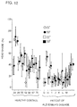
- Fig. 12 shows an example of head share of the head movement with respect to the line-of-sight sight provided by adding the head movement and the eye movement between gazing points.
- Fig. 1 is a schematic block diagram of one embodiment of the present invention.
- an eye movement detecting portion 2 detects eye movement of a subject, and the detection output thereof is applied to a calculating portion 1.
- a head movement detecting portion 3 detects the head movement of the subject, and the detection output thereof is applied to the calculating portion 1.
- the calculating portion 1 calculates the movement of the line-of-sight noting the movement of the line-of-sight of the subject to provide the velocity of the eye movement, the velocity of the head movement, the amplitude of the line-of-sight, characteristics of the movement of the line-of-sight, and the ratio of eye movement and of head movement in the movement of the line-of-sight, that is, head share, and the results are output to an output portion 4.
- a CRT display for example, is used as the output portion 4.
- the calculating portion 1 provides an instruction to the target presenting apparatus 5 to have the target presented to the subject.
- Fig. 2 shows an example in which the eye movement detecting portion 2 and the head movement detecting portion 3 shown in Fig. 1 are attached to goggles
- Fig. 3 shows a specific example of the head movement detecting portion
- Fig. 4 shows a specific example of the eye movement detecting portion 2.
- the goggles 8 shown in Fig. 2 which the subject wares have the eye movement detection portion 2 attached to a lower portion of one side thereof.
- the eye movement detecting portion 2 includes a light emitting diode 21 provided at the center and the photodiodes 22 and 23 provided on both sides thereof as shown in Fig. 4.
- a light emitting diode radiating infrared rays having relatively wide directivity of about ⁇ 21° is used as the light emitting diode 21, while ones having acute directivity of about ⁇ 10° are used as the photodiodes 22 and 23.
- the light beam emitted from the light emitting diode 21 to the eye ball 9 is reflected from the iris of the eye 10 and from the white of the eye 11 with different reflectivity, and the difference in reflectivity is amplified by an operational amplifier 25. If the difference is calculated, a horizontal output (left and right) is obtained as shown in Fig. 4(b), and if the sum is calculated by an operation amplifier 24, a vertical (up and down) output is obtained as shown in Fig. 4(c).
- the head movement detecting portion 3 is formed of a magnetic sensor as shown in Fig. 3. More specifically, the head movement detecting portion 3 includes a orthogonal coil serving as a source 31 and an orthogonal coil serving as a sensor 32. In accordance with an instruction from a control portion 33, a driving circuit 34 drives the orthogonal coil of the source 31 to generate a magnetic field. When the subject wearing the head movement detecting portion 3 moves, a voltage is induced in the sensor 32, which voltage is detected by the detecting circuit 35, the detected output therefrom is calculated by the control portion 33, and thus data corresponding to the movement of the head is output.
- Fig. 5 is an illustration of the target presenting apparatus 5 shown in Fig. 1.
- a target board is provided at a position apart by 1m from the subject, on which board light emitting diodes 51 - 55 are attached shifted by 25° from each other with respect to the subject at the center.
- the light emitting diodes 51 - 55 are lit in the order of 0° ⁇ 25° ⁇ 0° ⁇ 50° ⁇ 0° ⁇ -25° ⁇ 0° ⁇ -50° ⁇ 0° in response to the instructions from the calculating portion 1 shown in Fig. 1.
- Fig. 6 is an illustration showing the principle of the head coordinate system with the subject being the center.
- the head coordinate system detected by the head movement detecting portion 3 will be described.
- the head coordinate system includes two systems, that is, XY coordinate system realized by the translational movement of the subject with respect to the object of monitoring such as shown in Fig. 6(a), and a polar coordinate system based on the rotation movement of the head such as shown in Fig. 6(b).
- the amount of head movement in respective coordinate systems are defined as (Hx, Hy, Hz), (H ⁇ , H ⁇ , H ⁇ ).
- the direction toward the object of monitoring is represented by the Y axis
- the horizontal movement is represented by the X axis
- the vertical movement is represented by the Z axis, as an example.
- H ⁇ represents the rotation of the X axis, that is, the movement of one's neck upward or downward.
- H ⁇ represents the rotation of the Y axis, that is, the movement of inclining ones neck once from the left shoulder to the right shoulder.
- H ⁇ represents rotation in the Z axis, that is, rotation of one's neck in the left or right direction.
- Fig. 7 is a flow chart showing the operation of one embodiment of the present invention
- Figs. 8 - 12 show examples of display in accordance with one embodiment of the present invention.
- the calculating portion 1 in Fig. 1 have the target presenting apparatus 5 as in the same figure which presents the target to the subject. More specifically, the calculating portion 1 has the light emitting diodes 51 - 55 lit in the order of, for example, 0° ⁇ 25° ⁇ 0° ⁇ 50° ⁇ 0° ⁇ -25° ⁇ 0° ⁇ -50° ⁇ 0° as shown in Fig. 5, successively.
- the eye movement detecting portion 2 detects the eye movement of the subject, applies the data of the eye movement to the calculating portion 1.
- the head movement detecting portion 3 detects the head movement, and applies data of the head movement to the calculating portion 1.
- the calculating portion 1 takes the amount of head movement (Hx, Hy, Hz) and (H ⁇ , H ⁇ , H ⁇ ) of the head coordinate system described above with reference to Fig. 6 as the data of head movement, and in step SP3, it takes the eye coordinate system (Xe, Ye) as the data of the eye movement.
- the calculating portion 1 effects calculation of the equations (1) to (8) described above in each of the sampling periods i, i+1, i+2 ....
- H ⁇ i , H ⁇ i , H ⁇ i , Hx i , Hy i , Hz i , X'e i , Y'e i , Vx i and Vy i in each sampling period are obtained.
- the calculating portion 1 calculates the locus of the line-of-sight, the locus of the eye movement, the locus of the angle of head rotation and the locus of translational movement of the head. More specifically, the calculating portion 1 connects the line-of-sight (Vx i , Vy i ) and (Vx i+1 , Vy i+1 ) in the sampling period i, and calculates the locus of the line-of-sight. Further, the calculating portion 1 connects by the locus the eye movements (X'e i , Y'e i ) and (X'e i+1 , Y'e i+1 ) in the sampling period i, so as to calculate the locus of the eye movement.
- the calculating portion 1 calculates the locus of the angles of the head rotation (H ⁇ i , H ⁇ i ), (H ⁇ i+1 , H ⁇ i+1 ) in the sampling period i, so as to calculate the locus of the angle of the head rotation.
- the calculating portion 1 connects by a locus the translational movements of the head (Ex i , Ey i ) and (Ex i+1 , Ey i+1 ) to provide a locus of the translational movement of the head.
- the calculating portion 1 calculates velocities of various components in step SP6.
- the velocity v1 of the line-of-sight is calculated by the following equation (9) where Ts represents the sampling period.
- v1 ⁇ (Vx i+1 - Vx i )2 + (Vy i+1 - Vy i )2 ⁇ /Ts (9)
- the velocity v3 of the angle of head rotation is calculated by the following equation (11):
- v3 ⁇ (H ⁇ i+1 - H ⁇ i )2 + (H ⁇ i+1 - H ⁇ i )2 ⁇ /Ts (11)
- the velocity v4 of the translational movement of the head is calculated by the following equation (12):
- FIG. 8 (a), (d) and (g) show the data of a young healthy person.
- Figs. 8(b), (e) and (h) show the data of an aged healthy person.
- Figs. 8(c), (f) and (i) show data of a patient suffering from Alzheimer's disease.
- Figs. 8(a) - (c) show the locus a of the line-of-sight, the locus b of the eye movement, the locus c of the angle of head rotation and the locus d of the translational movement of the head with the time axis being the abscissa.
- FIG. 8(d), (e) and (f) show the velocity v1 of the line-of-sight and the velocity V2 of the eye movement with the time axis being the abscissa.
- Figs. 8(g), (h) and (i) show the velocity v3 of the angle of head rotation and the velocity v4 of the translational movement of the head with the time axis being the abscissa.
- the waveform (c+d) indicating the head movement of the patient of Alzheimer's disease is smaller than the one of the young healthy person, and as shown in Fig.
- the peak of the velocity v1 of the line-of-sight and the peak of the velocity v2 of the eye movement of the patient of Alzheimer's disease are larger than the young and aged healthy persons. Namely, it is recognized at one sight that the patient cannot reach straight the target but he reaches the target through some steps.
- the calculating portion 1 determines whether the disease comes from advance in age or the disease is Alzheimer's disease, and outputs the result to the output portion 4 in step SP8.
- step SP9 the calculating portion 1 calculates the peak velocity and the average velocity of the movement of the line-of-sight provided by adding samples of the head movement and the eye movement adjacent to each other on time basis, and displays the result at the output portion 4. As a result, the peak velocity is displayed in the manner as shown in Fig. 9 at the output portion 4. Further, in step SP10, the calculating portion 1 compares speed anisotropy of the left and right directions.
- Fig. 9(a) is an example of display of the peak velocities of six young and aged healthy persons, that is, A (24 years old), B (29 years old), C (35 years old), D (58 years old), E (67 years old) and F (75 years old).
- Fig. 9(a) is an example of display of the peak velocities of six young and aged healthy persons, that is, A (24 years old), B (29 years old), C (35 years old), D (58 years old), E (67 years old) and F (75 years old).
- FIG. 9(b) is an example of display of the peak velocities of seven patients suffering from Alzheimer's disease.
- the velocities in the left and right directions of the young and healthy persons are approximately uniform, while the velocity in the right direction is faster by 50°/sec to 100°/sec than the velocity in the left direction in the group of the patients of the Alzheimer's disease. This is used as a reference to discriminate Alzheimer's disease, and the result of discrimination is output to the output portion 4.
- step SP11 the calculating portion 1 calculates the average velocity component of the head movement, and outputs the result to the output portion 4 in the manner shown in Fig. 10.
- Fig. 10 (a) and (c) are examples of the healthy person, and (b) and (d) are examples of a patient suffering from Alzheimer's disease.
- the calculating portion 1 determines whether or not the velocity of the head movement is decreased in step SP12, and discriminates Alzheimer's disease from troubles popular among old persons.
- step SP13 after the gazing point separation, the calculating portion 1 calculates the head movement between gazing points, the eye movement, and the amplitude and head share of the movement of the line-of-sight obtained by adding the head and eye movements, and outputs the result to the output portion 4.
- the results are as shown in Figs. 11 and 12.
- Fig. 11 shows an example of the amplitude of the line-of-sight obtained by adding the head movement and the eye movement between gazing points.
- Fig. 12 shows an example of head share with respect to the line-of-sight obtained by adding the head movement and the eye movement between gazing points.
- step SP14 the calculating portion 1 discriminates a healthy person from a patient of Alzheimer's disease dependent on whether or not the gazing is imperfect.
- the determination of the gazing point is disclosed in, for example, Japanese Patent Laying-Open No. 2-156199 in which the velocity of the line-of-sight is used as a reference.
- the head share is decreased as the age is advanced in case of healthy persons.
- the head share of the patient of the Alzheimer's disease is further decreased and it is as small as 20% or less. Therefore in step SP15, the calculating portion 1 compares the ratio of decrease of the head share, and referring to the ratio of the head share, it determines the advance of the phenomena of aging and the advance of Alzheimer's disease.
- the calculation portion 1 provides the determinations such as shown in the following table 1.
- Table 1 DETERMINATION SHEET Name of Patient (1)Number of Stepwise Eye Movement (2)Anisotropy in velocity in left/right directions (3)Decrease of velocity of Head Movement (4)Imperfect Gazing (5)Decrease of Head Share ABC o o o o o DEF o o x x o XYZ x x o o o
- the doctor can discriminates the advance of the phenomena of aging from the advance of the Alzheimer's disease quickly.
- the output portion 4 shown in Fig. 1 is not limited to a CRT display, and the output may be provided to a telephone circuit through a printer or a modem.
- targets are presented to a subject, the eye movement of the subject at that time is detected, the spatial movement of the line-of-sight of the subject is calculated in response to the detected output and it is determined whether or not the disease is related to the brain function. Therefore, by referring to the movement of the line-of-sight, Alzheimer's disease can be immediately discriminated from the cerebrovascular disease, and this invention is promising in the field of clinical diagnosis and in the field of rehabilitation.
Landscapes
- Health & Medical Sciences (AREA)
- Life Sciences & Earth Sciences (AREA)
- Engineering & Computer Science (AREA)
- Public Health (AREA)
- General Health & Medical Sciences (AREA)
- Medical Informatics (AREA)
- Biomedical Technology (AREA)
- Veterinary Medicine (AREA)
- Animal Behavior & Ethology (AREA)
- Physics & Mathematics (AREA)
- Surgery (AREA)
- Biophysics (AREA)
- Molecular Biology (AREA)
- Heart & Thoracic Surgery (AREA)
- Neurology (AREA)
- Physiology (AREA)
- Pathology (AREA)
- Ophthalmology & Optometry (AREA)
- Human Computer Interaction (AREA)
- Neurosurgery (AREA)
- Developmental Disabilities (AREA)
- Child & Adolescent Psychology (AREA)
- Psychology (AREA)
- Dentistry (AREA)
- Oral & Maxillofacial Surgery (AREA)
- Epidemiology (AREA)
- Primary Health Care (AREA)
- Hospice & Palliative Care (AREA)
- Psychiatry (AREA)
- Eye Examination Apparatus (AREA)
Applications Claiming Priority (2)
| Application Number | Priority Date | Filing Date | Title |
|---|---|---|---|
| JP4182227A JPH0655203B2 (ja) | 1992-07-09 | 1992-07-09 | 視線検出を用いた医療診断装置 |
| JP182227/92 | 1992-07-09 |
Publications (3)
| Publication Number | Publication Date |
|---|---|
| EP0578908A2 true EP0578908A2 (fr) | 1994-01-19 |
| EP0578908A3 EP0578908A3 (fr) | 1995-02-22 |
| EP0578908B1 EP0578908B1 (fr) | 1997-07-09 |
Family
ID=16114571
Family Applications (1)
| Application Number | Title | Priority Date | Filing Date |
|---|---|---|---|
| EP93100563A Expired - Lifetime EP0578908B1 (fr) | 1992-07-09 | 1993-01-15 | Appareil de diagnostique médical utilisant la détection de la direction du regard |
Country Status (6)
| Country | Link |
|---|---|
| US (1) | US5311879A (fr) |
| EP (1) | EP0578908B1 (fr) |
| JP (1) | JPH0655203B2 (fr) |
| KR (1) | KR960006650B1 (fr) |
| CA (1) | CA2086066C (fr) |
| DE (1) | DE69311980T2 (fr) |
Cited By (6)
| Publication number | Priority date | Publication date | Assignee | Title |
|---|---|---|---|---|
| EP1260177A3 (fr) * | 2001-05-25 | 2003-01-08 | Eastman Kodak Company | Analyse de saccades pour la détermination de troubles déficitaires de l'attention avec hyperactivité |
| WO2002065898A3 (fr) * | 2001-02-19 | 2003-12-24 | Fraunhofer Ges Forschung | Dispositif et procede pour determiner la direction du regard relativement a un systeme fixe de coordonnees de reference |
| EP1931240A4 (fr) * | 2005-09-13 | 2009-11-18 | Welch Allyn Inc | Diagnostic de maladies ophtalmiques identifiables par voie optique |
| US7708403B2 (en) | 2003-10-30 | 2010-05-04 | Welch Allyn, Inc. | Apparatus and method for diagnosis of optically identifiable ophthalmic conditions |
| US9060728B2 (en) | 2003-10-30 | 2015-06-23 | Welch Allyn, Inc. | Apparatus for health correlation assessment |
| IT201800003484A1 (it) * | 2018-03-13 | 2019-09-13 | Alessandro Florian | Sistema e metodo per la rieducazione dell’apparato oculo-vestibolare |
Families Citing this family (26)
| Publication number | Priority date | Publication date | Assignee | Title |
|---|---|---|---|---|
| US6778150B1 (en) * | 1993-09-14 | 2004-08-17 | Francis J. Maguire, Jr. | Method and apparatus for eye tracking |
| US6359601B1 (en) | 1993-09-14 | 2002-03-19 | Francis J. Maguire, Jr. | Method and apparatus for eye tracking |
| JP3293308B2 (ja) * | 1994-03-10 | 2002-06-17 | 三菱電機株式会社 | 人物状態検出装置 |
| US7453451B1 (en) | 1999-03-16 | 2008-11-18 | Maguire Francis J Jr | Moveable headrest for viewing images from different directions |
| US6181371B1 (en) * | 1995-05-30 | 2001-01-30 | Francis J Maguire, Jr. | Apparatus for inducing attitudinal head movements for passive virtual reality |
| US5956125A (en) * | 1997-06-19 | 1999-09-21 | Bioprobes, Inc. | System and method for screening for dementia |
| DE19809591A1 (de) * | 1998-03-06 | 1999-09-09 | Neuhof | Vorrichtung und Verfahren zur Darbietung von bewegten oder unbewegten Seheindrücken zur automatischen und umfassenden Erfassung zahlreicher Parameter des Betrachters |
| EP1357831A2 (fr) * | 2001-02-09 | 2003-11-05 | Sensomotoric Instruments GmbH | Systeme de mesure de position de l'oeil et de poursuite oculaire a dimensions multiples pour le diagnostic et le traitement de l'oeil |
| US7959674B2 (en) * | 2002-07-16 | 2011-06-14 | Medtronic, Inc. | Suture locking assembly and method of use |
| JP3598385B2 (ja) * | 2002-10-17 | 2004-12-08 | 独立行政法人情報通信研究機構 | 高次脳機能障害診断装置 |
| EP1749511A4 (fr) | 2004-05-26 | 2009-04-01 | Panasonic Elec Works Co Ltd | Dispositif de formation de fonction cognitive |
| US20080058681A1 (en) * | 2006-08-30 | 2008-03-06 | Casali Henry Eloy S | Portable system for monitoring the position of a patient's head during videonystagmography tests (VNG) or electronystagmography (ENG) |
| ITRM20070526A1 (it) * | 2007-10-05 | 2009-04-06 | Univ Roma | Apparato di acquisizione ed elaborazione delle informazioni relative ad attivita oculari umane |
| KR101032832B1 (ko) * | 2009-04-20 | 2011-05-06 | 김종성 | 액화산소를 열원으로 하는 완전연소식 고효율 열풍기의 연소방법 |
| KR20230044041A (ko) | 2013-03-11 | 2023-03-31 | 매직 립, 인코포레이티드 | 증강 및 가상 현실을 위한 시스템 및 방법 |
| CN109124657B (zh) * | 2013-03-11 | 2021-11-23 | 亚特兰大儿童医疗保健公司 | 用于认知和发育状况的检测的系统和方法 |
| CN105229719B (zh) | 2013-03-15 | 2018-04-27 | 奇跃公司 | 显示系统和方法 |
| KR20150140814A (ko) * | 2013-04-10 | 2015-12-16 | 오클랜드 유니서비시즈 리미티드 | 머리 및 눈 추적 |
| TWI489320B (zh) * | 2013-10-25 | 2015-06-21 | Utechzone Co Ltd | 電子文件標記方法及裝置 |
| JP7123539B2 (ja) * | 2017-09-21 | 2022-08-23 | 日清オイリオグループ株式会社 | 診断支援情報提供装置 |
| KR102698364B1 (ko) | 2017-10-26 | 2024-08-23 | 매직 립, 인코포레이티드 | 증강 현실 디스플레이를 위한 광대역 적응형 렌즈 어셈블리 |
| CA3081199A1 (fr) | 2017-11-14 | 2019-05-23 | Osaka University | Appareil de diagnostic de dysfonctionnement cognitif et programme de diagnostic de dysfonctionnement cognitif |
| JP2021536592A (ja) | 2018-08-31 | 2021-12-27 | マジック リープ, インコーポレイテッドMagic Leap, Inc. | 拡張現実デバイスのための空間的に分解された動的調光 |
| JP7585206B2 (ja) | 2019-01-11 | 2024-11-18 | マジック リープ, インコーポレイテッド | 種々の深度における仮想コンテンツの時間多重化された表示 |
| CN110693459B (zh) * | 2019-10-31 | 2022-04-29 | 北京乐器研究所 | 诊断阿尔茨海默症的应用及诊断阿尔茨海默症的装置 |
| CN115315217B (zh) | 2020-03-27 | 2026-01-02 | 国立大学法人大阪大学 | 认知功能障碍诊断装置以及认知功能障碍诊断程序记录介质 |
Family Cites Families (8)
| Publication number | Priority date | Publication date | Assignee | Title |
|---|---|---|---|---|
| US4158920A (en) * | 1977-02-23 | 1979-06-26 | Walker Norman K | Method and apparatus for testing for brain dysfunction in a human |
| US4582403A (en) * | 1984-03-05 | 1986-04-15 | Weinblatt Lee S | Head movement correction technique for eye-movement monitoring system |
| US4889422A (en) * | 1986-01-28 | 1989-12-26 | George Pavlidis | Method and means for detecting dyslexia |
| US4838681A (en) * | 1986-01-28 | 1989-06-13 | George Pavlidis | Method and means for detecting dyslexia |
| FR2608036B1 (fr) * | 1986-12-11 | 1989-03-03 | Inst Nat Sante Rech Med | Procede de detection de la direction du regard par analyse du signal electrooculographique et dispositif pour la mise en oeuvre dudit procede |
| US4848340A (en) * | 1988-02-10 | 1989-07-18 | Intelligent Surgical Lasers | Eyetracker and method of use |
| JPH02156199A (ja) * | 1988-12-08 | 1990-06-15 | Ishikawajima Harima Heavy Ind Co Ltd | 放射性廃棄物の固定化方法 |
| JPH02164335A (ja) * | 1988-12-16 | 1990-06-25 | Konan Camera Kenkyusho:Kk | 眼球運動解析装置 |
-
1992
- 1992-07-09 JP JP4182227A patent/JPH0655203B2/ja not_active Expired - Fee Related
- 1992-12-18 US US07/995,651 patent/US5311879A/en not_active Expired - Fee Related
- 1992-12-22 CA CA002086066A patent/CA2086066C/fr not_active Expired - Fee Related
-
1993
- 1993-01-15 DE DE69311980T patent/DE69311980T2/de not_active Expired - Fee Related
- 1993-01-15 EP EP93100563A patent/EP0578908B1/fr not_active Expired - Lifetime
- 1993-03-12 KR KR1019930003712A patent/KR960006650B1/ko not_active Expired - Fee Related
Cited By (10)
| Publication number | Priority date | Publication date | Assignee | Title |
|---|---|---|---|---|
| WO2002065898A3 (fr) * | 2001-02-19 | 2003-12-24 | Fraunhofer Ges Forschung | Dispositif et procede pour determiner la direction du regard relativement a un systeme fixe de coordonnees de reference |
| EP1260177A3 (fr) * | 2001-05-25 | 2003-01-08 | Eastman Kodak Company | Analyse de saccades pour la détermination de troubles déficitaires de l'attention avec hyperactivité |
| US7708403B2 (en) | 2003-10-30 | 2010-05-04 | Welch Allyn, Inc. | Apparatus and method for diagnosis of optically identifiable ophthalmic conditions |
| US8075136B2 (en) | 2003-10-30 | 2011-12-13 | Welch Allyn, Inc. | Apparatus and method of diagnosis of optically identifiable ophthalmic conditions |
| US8439501B2 (en) | 2003-10-30 | 2013-05-14 | Welch Allyn, Inc. | Diagnosis of optically identifiable ophthalmic conditions |
| US8702234B2 (en) | 2003-10-30 | 2014-04-22 | Welch Allyn, Inc. | Diagnosis of optically identifiable ophthalmic conditions |
| US9060728B2 (en) | 2003-10-30 | 2015-06-23 | Welch Allyn, Inc. | Apparatus for health correlation assessment |
| US9563742B2 (en) | 2003-10-30 | 2017-02-07 | Welch Allyn, Inc. | Apparatus for diagnosis of optically identifiable ophthalmic conditions |
| EP1931240A4 (fr) * | 2005-09-13 | 2009-11-18 | Welch Allyn Inc | Diagnostic de maladies ophtalmiques identifiables par voie optique |
| IT201800003484A1 (it) * | 2018-03-13 | 2019-09-13 | Alessandro Florian | Sistema e metodo per la rieducazione dell’apparato oculo-vestibolare |
Also Published As
| Publication number | Publication date |
|---|---|
| DE69311980T2 (de) | 1998-01-02 |
| EP0578908B1 (fr) | 1997-07-09 |
| CA2086066A1 (fr) | 1994-01-10 |
| EP0578908A3 (fr) | 1995-02-22 |
| KR960006650B1 (ko) | 1996-05-22 |
| CA2086066C (fr) | 1996-04-30 |
| US5311879A (en) | 1994-05-17 |
| KR940001859A (ko) | 1994-02-16 |
| JPH0655203B2 (ja) | 1994-07-27 |
| JPH0670885A (ja) | 1994-03-15 |
| DE69311980D1 (de) | 1997-08-14 |
Similar Documents
| Publication | Publication Date | Title |
|---|---|---|
| EP0578908A2 (fr) | Appareil de diagnostique médical utilisant la détection de la direction du regard | |
| US5305764A (en) | Medical diagnostic apparatus utilizing line-of-sight detection | |
| US5382989A (en) | Apparatus for examining gaze shift in depth direction | |
| US5365941A (en) | Apparatus for detecting small involuntary movement | |
| EP0582772B1 (fr) | Appareil pour diagnostic médical de maladies cérébrales | |
| EP0590231B1 (fr) | Appareil d'analyse pour perception de la profondeur | |
| US8371693B2 (en) | Autism diagnosis support apparatus | |
| US7680302B2 (en) | Method and apparatus for detection of drowsiness and quantitative control of biological processes | |
| US6381339B1 (en) | Image system evaluation method and apparatus using eye motion tracking | |
| Imai et al. | Rotation vector analysis of eye movement in three dimensions with an infrared CCD camera | |
| KR20010041665A (ko) | 운동 패턴 평가 방법 및 장치 | |
| Kono et al. | Suppression of vestibulo-ocular reflex with increased mental workload while driving | |
| KR20230093990A (ko) | 가상현실 기반 시선추적을 통한 의식장애평가장치 | |
| Komatsu et al. | Behavioral evidence of filling-in at the blind spot of the monkey | |
| HK1007412B (en) | An apparatus for medical diagnosis of brain diseases | |
| RU2442526C1 (ru) | Специализированная видеокамера контроля оператора | |
| Ramdane-Cherif et al. | Performance of a computer system for recording and analysing eye gaze position using an infrared light device | |
| Wu et al. | Computerised infrared imaging system for studying thermal activation on the skull following somatic stimulation in small animals |
Legal Events
| Date | Code | Title | Description |
|---|---|---|---|
| PUAI | Public reference made under article 153(3) epc to a published international application that has entered the european phase |
Free format text: ORIGINAL CODE: 0009012 |
|
| AK | Designated contracting states |
Kind code of ref document: A2 Designated state(s): DE FR GB NL SE |
|
| PUAL | Search report despatched |
Free format text: ORIGINAL CODE: 0009013 |
|
| AK | Designated contracting states |
Kind code of ref document: A3 Designated state(s): DE FR GB NL SE |
|
| 17P | Request for examination filed |
Effective date: 19950320 |
|
| 17Q | First examination report despatched |
Effective date: 19960521 |
|
| GRAG | Despatch of communication of intention to grant |
Free format text: ORIGINAL CODE: EPIDOS AGRA |
|
| GRAH | Despatch of communication of intention to grant a patent |
Free format text: ORIGINAL CODE: EPIDOS IGRA |
|
| GRAH | Despatch of communication of intention to grant a patent |
Free format text: ORIGINAL CODE: EPIDOS IGRA |
|
| GRAA | (expected) grant |
Free format text: ORIGINAL CODE: 0009210 |
|
| AK | Designated contracting states |
Kind code of ref document: B1 Designated state(s): DE FR GB NL SE |
|
| ET | Fr: translation filed | ||
| REF | Corresponds to: |
Ref document number: 69311980 Country of ref document: DE Date of ref document: 19970814 |
|
| PLBE | No opposition filed within time limit |
Free format text: ORIGINAL CODE: 0009261 |
|
| STAA | Information on the status of an ep patent application or granted ep patent |
Free format text: STATUS: NO OPPOSITION FILED WITHIN TIME LIMIT |
|
| 26N | No opposition filed | ||
| PGFP | Annual fee paid to national office [announced via postgrant information from national office to epo] |
Ref country code: NL Payment date: 20011220 Year of fee payment: 10 |
|
| REG | Reference to a national code |
Ref country code: GB Ref legal event code: IF02 |
|
| PGFP | Annual fee paid to national office [announced via postgrant information from national office to epo] |
Ref country code: GB Payment date: 20020102 Year of fee payment: 10 |
|
| PGFP | Annual fee paid to national office [announced via postgrant information from national office to epo] |
Ref country code: SE Payment date: 20020124 Year of fee payment: 10 |
|
| PGFP | Annual fee paid to national office [announced via postgrant information from national office to epo] |
Ref country code: FR Payment date: 20020129 Year of fee payment: 10 |
|
| PGFP | Annual fee paid to national office [announced via postgrant information from national office to epo] |
Ref country code: DE Payment date: 20020201 Year of fee payment: 10 |
|
| PG25 | Lapsed in a contracting state [announced via postgrant information from national office to epo] |
Ref country code: GB Free format text: LAPSE BECAUSE OF NON-PAYMENT OF DUE FEES Effective date: 20030115 |
|
| PG25 | Lapsed in a contracting state [announced via postgrant information from national office to epo] |
Ref country code: SE Free format text: LAPSE BECAUSE OF NON-PAYMENT OF DUE FEES Effective date: 20030116 |
|
| PG25 | Lapsed in a contracting state [announced via postgrant information from national office to epo] |
Ref country code: NL Free format text: LAPSE BECAUSE OF NON-PAYMENT OF DUE FEES Effective date: 20030801 Ref country code: DE Free format text: LAPSE BECAUSE OF NON-PAYMENT OF DUE FEES Effective date: 20030801 |
|
| EUG | Se: european patent has lapsed | ||
| GBPC | Gb: european patent ceased through non-payment of renewal fee | ||
| PG25 | Lapsed in a contracting state [announced via postgrant information from national office to epo] |
Ref country code: FR Free format text: LAPSE BECAUSE OF NON-PAYMENT OF DUE FEES Effective date: 20030930 |
|
| NLV4 | Nl: lapsed or anulled due to non-payment of the annual fee |
Effective date: 20030801 |
|
| REG | Reference to a national code |
Ref country code: FR Ref legal event code: ST |