EP0579003A1 - Einbruchhemmende Vorrichtung für ein Schloss mit drehbarem Riegel - Google Patents
Einbruchhemmende Vorrichtung für ein Schloss mit drehbarem Riegel Download PDFInfo
- Publication number
- EP0579003A1 EP0579003A1 EP93110019A EP93110019A EP0579003A1 EP 0579003 A1 EP0579003 A1 EP 0579003A1 EP 93110019 A EP93110019 A EP 93110019A EP 93110019 A EP93110019 A EP 93110019A EP 0579003 A1 EP0579003 A1 EP 0579003A1
- Authority
- EP
- European Patent Office
- Prior art keywords
- bolt
- plate
- pawl
- lock
- actuated
- Prior art date
- Legal status (The legal status is an assumption and is not a legal conclusion. Google has not performed a legal analysis and makes no representation as to the accuracy of the status listed.)
- Withdrawn
Links
- 230000000903 blocking effect Effects 0.000 claims abstract description 5
- 230000008878 coupling Effects 0.000 description 2
- 238000010168 coupling process Methods 0.000 description 2
- 238000005859 coupling reaction Methods 0.000 description 2
- 230000000670 limiting effect Effects 0.000 description 1
- 230000004048 modification Effects 0.000 description 1
- 238000012986 modification Methods 0.000 description 1
- 230000000284 resting effect Effects 0.000 description 1
Images



Classifications
-
- E—FIXED CONSTRUCTIONS
- E05—LOCKS; KEYS; WINDOW OR DOOR FITTINGS; SAFES
- E05B—LOCKS; ACCESSORIES THEREFOR; HANDCUFFS
- E05B63/00—Locks or fastenings with special structural characteristics
- E05B63/0013—Locks with rotary bolt without provision for latching
Definitions
- the present invention relates to a burglar-proof device for a lock with swivel bolt.
- a technical aim of the present invention is to propose a device which prevents the unauthorized retraction of the swivel bolt into the lock once it has been rotated into the engagement position in the selvage.
- an object of the present invention is to provide a device which is structurally simple and therefore such that it does not negatively affect the cost of the lock and that it ensures the reliability of the lock in operation.
- a burglar-proof device for a lock with a swivel bolt wherein the bolt is articulated in the lock case and is rotatable, by means of a plate actuated by the plug of a cylinder, between a position in which it is inside the case and a position in which it is outside the case and engages the selvage, characterized in that a pawl is articulated in the case and cooperates with said plate so that, when the plate has actuated the bolt into said external position, said pawl is in a bolt blocking position, whereas when said plate is actuated to move said bolt into said internal position, said pawl is first actuated into the bolt release position by said plate.
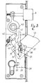
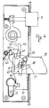
- figures 1 to 5 are views of a lock with a swivel bolt in five operating positions of the burglar-proof device; and figure 6 is a side view of the bolt, illustrating some constructive details.
- the lock comprises a case including a side wall 1 from which rise an upper wall 2, a lower wall 3 and a front wall 4, as well as a series of threaded bushes 5 in which respective screws for fixing a lateral closure cover of the case, not shown in the drawing, are screwed.
- a faceplate 6 is associated with the front wall 4 and is meant to close the seat of the door in which the lock is flush-fitted.
- An opening 7 is formed in the faceplate 6 and in the wall 4 adjacent thereto; the spring-latch 8 of the lock protrudes outwards through said opening.
- the spring-latch 8 is provided with a tang 9 guided in a wing 10 which rises from the wall 1 and is provided with a collar 11 on which a spring 12 acts; said spring rests on a lug 13 obtained by folding the rear edge of the wall 1.
- the end of an arm 14 is interposed between the wing 10 and the collar 11; said arm extends radially from a pivoting ring 15 pivoted on a ferrule 16 which is in turn rotatably supported in seats of the wall 1 and of the cover.
- the ferrule 16 (also provided with an arm, not shown in the drawing, which acts on the collar 11 independently of the arm 14) is crossed by a square hole 16a for the side-fitting coupling of a handle for the manual actuation of the spring-latch 8. Below the opening 7 of the spring-latch 8 there is a second opening 17 through which a bolt 18 acting as a swivel bolt can protrude outside.
- the bolt 18 is articulated inside the case by a pivot 19 inserted in the wall 1, with which it is rigidly associated; said bolt is rotatable between a position in which it is inside the case (see figure 1) and a position in which it is outside said case (see figure 5).
- the bolt 18 is substantially rectangular, with an edge 20 which frontally closes the opening 17 when the bolt is in closure position and is perpendicular to the faceplate 6 when the bolt is in protruding position.
- the recess 21 is triangular, with a side 23 substantially parallel to the edge 20 and a side 24 substantially perpendicular to said edge which form angles 25, 26 and 27.
- the recess 22 intersects the recess 21 at the corner 26 formed between the sides 23 and 24, and is shaped so that it accommodates a spring 28 having a portion 29 which passes through the angle 26 and is foldable within the recess 22.
- a plate 30 is arranged adjacent to the bolt 18 and has, at its lower end, a notch 31 in which the plug 32 of a cylinder 32a is engageable; said cylinder is placed, in a conventional manner, in its seat 33 formed in the wall 1 and in the cover.
- a slot 34 is formed in the plate 30, is elongated parallel to the faceplate 6 and comprises two portions 35 and 36 aligned and mutually connected by a portion 37 shaped like a circular arc.
- a pivot 38 is fixed at the center of curvature of the portion 37 in the plate 30, protrudes from the face opposite to the one shown in the figure and engages the recess 21.
- the slot 34 is crossed by the pivot 19 which, in cooperation with the wall 4 against which the corner 39 of the plate 30 slides, keeps said plate 30 guided parallel to the faceplate 6.
- the plate 30 has, at its upper end, a finger 40 on the side whereof an upwardly open recess 41 is formed. Said recess 41 is engaged by a tooth 42, shown in dashed lines in the drawing since it protrudes from the cover closing the case of the lock.
- the finger 40 is suitable to act against a shoulder 43 formed in the pivoting ring 15 when actuating the spring-latch by acting with the key of the cylinder 32.
- the plate 30 On the side of the recess 41 which is opposite to the finger 40, the plate 30 forms an angle 44 on which a pawl 45 rests; said pawl is articulated by a pivot 46 rigidly coupled to the wall 1.
- the pawl 45 is kept resting on the corner 44 by a spring 47, one end of which abuts on a pin 48 inserted in the wall 1 and the opposite end of which abuts on a step 49 of the pawl 45.
- the pawl 45 furthermore has a depression 50 which, during the actuation of the lock, allows it to pass below the plate 30 to enter a seat 51 formed on the edge of the bolt which is opposite to the edge 20.
- the plug 32 By actuating the cylinder 32a, the plug 32 engages the notch 31 and causes a downward movement of the plate 30, the pivot 38 of which, by acting on the portion 29 of the spring 28 and overcoming its resistance, moves at the corner 26, whereas the pivot 19 reaches the connecting point between the portions 35 and 37.
- the movement of the plate simultaneously causes the disengagement of the tooth 42 from the recess 41 (position of figure 2).
- the further action of the plug 32 on the plate 30, by virtue of the thrust of the pivot 38 against the wall 24 of the recess 21, causes the rotation of the bolt about the pivot 19, during which the pivot 19 moves along the arc-like portion 37 of the slot 34.
- the blocking action of the pawl 45 adds to the locking action performed by the engagement of the pivot 38 in the recess 21, which has often turned out to be insufficient on its own due to the low strength of the coupling of the pivot 38 to the plate 30.
- the pivot 38 might disengage from the recess 21, allowing the forced retraction of the bolt into the lock.
- the pawl 45 does not hinder the normal actuation of the bolt by means of the cylinder 32.
- the plate 30 can perform a first stroke sufficient to raise the pawl 45 out of the seat 51 to allow the subsequent rotation of the bolt in reverse with respect to the above description, i.e. according to the sequence of figures 3, 2 and 1.
- the device according to the invention is susceptible to numerous constructively equivalent modifications and variations.
- the pawl 45 can be operatively connected to the plate 30 with a slot link instead of using a spring 47.
Landscapes
- Engineering & Computer Science (AREA)
- Structural Engineering (AREA)
- Lock And Its Accessories (AREA)
Applications Claiming Priority (2)
| Application Number | Priority Date | Filing Date | Title |
|---|---|---|---|
| IT92BO000140U IT227896Y1 (it) | 1992-06-25 | 1992-06-25 | Dispositivo antiscasso per una serratura con catenaccio a paletto |
| ITBO920140U | 1992-06-25 |
Publications (1)
| Publication Number | Publication Date |
|---|---|
| EP0579003A1 true EP0579003A1 (de) | 1994-01-19 |
Family
ID=11338175
Family Applications (1)
| Application Number | Title | Priority Date | Filing Date |
|---|---|---|---|
| EP93110019A Withdrawn EP0579003A1 (de) | 1992-06-25 | 1993-06-23 | Einbruchhemmende Vorrichtung für ein Schloss mit drehbarem Riegel |
Country Status (2)
| Country | Link |
|---|---|
| EP (1) | EP0579003A1 (de) |
| IT (1) | IT227896Y1 (de) |
Cited By (3)
| Publication number | Priority date | Publication date | Assignee | Title |
|---|---|---|---|---|
| EP0677634A1 (de) * | 1994-04-13 | 1995-10-18 | KARL FLIETHER GmbH & Co. | Insbesondere an Wohnungsabschlusstüren einzusetzendes Schloss, insbesondere Treibstangenschloss |
| CN102137979A (zh) * | 2008-08-05 | 2011-07-27 | 西莎股份公司 | 推拉门的通用锁 |
| US8485569B2 (en) | 2007-01-05 | 2013-07-16 | Adams Rite Europe Limited | Lock assembly |
Citations (6)
| Publication number | Priority date | Publication date | Assignee | Title |
|---|---|---|---|---|
| US3235298A (en) * | 1963-01-16 | 1966-02-15 | Yale & Towne Inc | Deadlatching lock |
| US3390908A (en) * | 1965-03-04 | 1968-07-02 | Schlage Lock Co | Pivoted blade lock device |
| US3695068A (en) * | 1970-07-13 | 1972-10-03 | Adams Rite Mfg | Narrow stile latch-lock structure |
| DE2409824A1 (de) * | 1974-03-01 | 1975-09-11 | Kirchmann Niederdrenk Kg | Sicherheitsschloss |
| EP0010684A1 (de) * | 1978-10-20 | 1980-05-14 | van Parys, Remi Emiel | Schloss |
| US4387918A (en) * | 1979-02-28 | 1983-06-14 | Ogden Industries Pty. Ltd. | Deadlock mechanism |
-
1992
- 1992-06-25 IT IT92BO000140U patent/IT227896Y1/it active IP Right Grant
-
1993
- 1993-06-23 EP EP93110019A patent/EP0579003A1/de not_active Withdrawn
Patent Citations (6)
| Publication number | Priority date | Publication date | Assignee | Title |
|---|---|---|---|---|
| US3235298A (en) * | 1963-01-16 | 1966-02-15 | Yale & Towne Inc | Deadlatching lock |
| US3390908A (en) * | 1965-03-04 | 1968-07-02 | Schlage Lock Co | Pivoted blade lock device |
| US3695068A (en) * | 1970-07-13 | 1972-10-03 | Adams Rite Mfg | Narrow stile latch-lock structure |
| DE2409824A1 (de) * | 1974-03-01 | 1975-09-11 | Kirchmann Niederdrenk Kg | Sicherheitsschloss |
| EP0010684A1 (de) * | 1978-10-20 | 1980-05-14 | van Parys, Remi Emiel | Schloss |
| US4387918A (en) * | 1979-02-28 | 1983-06-14 | Ogden Industries Pty. Ltd. | Deadlock mechanism |
Cited By (3)
| Publication number | Priority date | Publication date | Assignee | Title |
|---|---|---|---|---|
| EP0677634A1 (de) * | 1994-04-13 | 1995-10-18 | KARL FLIETHER GmbH & Co. | Insbesondere an Wohnungsabschlusstüren einzusetzendes Schloss, insbesondere Treibstangenschloss |
| US8485569B2 (en) | 2007-01-05 | 2013-07-16 | Adams Rite Europe Limited | Lock assembly |
| CN102137979A (zh) * | 2008-08-05 | 2011-07-27 | 西莎股份公司 | 推拉门的通用锁 |
Also Published As
| Publication number | Publication date |
|---|---|
| ITBO920140V0 (it) | 1992-06-25 |
| ITBO920140U1 (it) | 1993-12-25 |
| IT227896Y1 (it) | 1998-01-21 |
Similar Documents
| Publication | Publication Date | Title |
|---|---|---|
| US4237711A (en) | Lock mechanism | |
| US4429556A (en) | Lock mechanism | |
| US4583382A (en) | Reversible latch assembly with integrated function | |
| US6578888B1 (en) | Mortise lock with automatic deadbolt | |
| US5784909A (en) | Control mechanism for tubular locks | |
| US5878606A (en) | Door lock for swinging door | |
| US4218903A (en) | Lock mechanism | |
| US4440006A (en) | Antitheft central lock system for a motor vehicle | |
| CA1040233A (en) | Lock knob control mechanism | |
| US8266934B2 (en) | Keyed cylinder assembly for door lock | |
| US20010029760A1 (en) | Lock mechanism | |
| US5819562A (en) | Door lock having multiple locking bolts | |
| US3781045A (en) | Motor-vehicle door latch with lock mechanism only actuatable with door closed | |
| US5771720A (en) | Z-bar security system with key and secured latch | |
| JPH0726496B2 (ja) | 安全装置の内設されたドア・ロック | |
| JPH08135279A (ja) | 左右兼用型扉用ロックハンドル装置 | |
| US20020038561A1 (en) | Panic door lock | |
| US5094486A (en) | Dead bolt assembly | |
| US3031876A (en) | Master key controlled permutation locks | |
| GB2225607A (en) | Improvements in or relating to locks | |
| JP4231595B2 (ja) | 施錠装置 | |
| US3235298A (en) | Deadlatching lock | |
| WO1997033060A1 (en) | A lockset | |
| JPH0613989Y2 (ja) | 金庫扉のロック機構 | |
| GB2306559A (en) | Locks |
Legal Events
| Date | Code | Title | Description |
|---|---|---|---|
| PUAI | Public reference made under article 153(3) epc to a published international application that has entered the european phase |
Free format text: ORIGINAL CODE: 0009012 |
|
| AK | Designated contracting states |
Kind code of ref document: A1 Designated state(s): DE ES |
|
| 17P | Request for examination filed |
Effective date: 19940708 |
|
| 17Q | First examination report despatched |
Effective date: 19941103 |
|
| 18D | Application deemed to be withdrawn |
Effective date: 19950314 |
|
| D18D | Application deemed to be withdrawn (deleted) | ||
| STAA | Information on the status of an ep patent application or granted ep patent |
Free format text: STATUS: THE APPLICATION IS DEEMED TO BE WITHDRAWN |
|
| R18D | Application deemed to be withdrawn (corrected) |
Effective date: 19960103 |