EP0579009A1 - Verfahren und Vorrichtung zum Einlegen von Chargiermaterial in Glasschmelzöfen - Google Patents
Verfahren und Vorrichtung zum Einlegen von Chargiermaterial in Glasschmelzöfen Download PDFInfo
- Publication number
- EP0579009A1 EP0579009A1 EP93110083A EP93110083A EP0579009A1 EP 0579009 A1 EP0579009 A1 EP 0579009A1 EP 93110083 A EP93110083 A EP 93110083A EP 93110083 A EP93110083 A EP 93110083A EP 0579009 A1 EP0579009 A1 EP 0579009A1
- Authority
- EP
- European Patent Office
- Prior art keywords
- slide
- charging
- drive
- movement
- slide carrier
- Prior art date
- Legal status (The legal status is an assumption and is not a legal conclusion. Google has not performed a legal analysis and makes no representation as to the accuracy of the status listed.)
- Withdrawn
Links
- 238000002844 melting Methods 0.000 title claims abstract description 24
- 230000008018 melting Effects 0.000 title claims abstract description 24
- 239000011521 glass Substances 0.000 title claims abstract description 22
- 239000000463 material Substances 0.000 title claims abstract description 16
- 238000000034 method Methods 0.000 title claims abstract description 10
- 238000005816 glass manufacturing process Methods 0.000 title abstract 2
- 210000004907 gland Anatomy 0.000 claims abstract description 9
- 239000000155 melt Substances 0.000 claims abstract description 9
- 238000003780 insertion Methods 0.000 claims description 36
- 230000037431 insertion Effects 0.000 claims description 36
- 239000000969 carrier Substances 0.000 claims description 6
- 239000000919 ceramic Substances 0.000 claims description 2
- 238000007789 sealing Methods 0.000 abstract description 8
- 238000010276 construction Methods 0.000 description 3
- 238000012966 insertion method Methods 0.000 description 3
- 235000004443 Ricinus communis Nutrition 0.000 description 2
- 240000000528 Ricinus communis Species 0.000 description 2
- 238000002485 combustion reaction Methods 0.000 description 2
- 239000000498 cooling water Substances 0.000 description 2
- 210000003746 feather Anatomy 0.000 description 2
- 239000000156 glass melt Substances 0.000 description 2
- 230000000737 periodic effect Effects 0.000 description 2
- 230000000712 assembly Effects 0.000 description 1
- 238000000429 assembly Methods 0.000 description 1
- 230000005540 biological transmission Effects 0.000 description 1
- 239000002826 coolant Substances 0.000 description 1
- 238000001816 cooling Methods 0.000 description 1
- 238000006073 displacement reaction Methods 0.000 description 1
- 230000000694 effects Effects 0.000 description 1
- 238000007654 immersion Methods 0.000 description 1
- 230000001771 impaired effect Effects 0.000 description 1
- 239000002557 mineral fiber Substances 0.000 description 1
- 238000005192 partition Methods 0.000 description 1
- 238000000926 separation method Methods 0.000 description 1
- 230000001360 synchronised effect Effects 0.000 description 1
Images




Classifications
-
- C—CHEMISTRY; METALLURGY
- C03—GLASS; MINERAL OR SLAG WOOL
- C03B—MANUFACTURE, SHAPING, OR SUPPLEMENTARY PROCESSES
- C03B3/00—Charging the melting furnaces
Definitions
- the invention relates to a method for inserting charging material from a batch container through a heat shield and an insertion opening onto the molten bath surface of glass melting furnaces by means of at least one plate-shaped slider which has a lower edge running parallel to the molten bath surface and executes slide movements with horizontal and vertical components while charging material is continuously on the melt pool surface is abandoned.
- the slide In the conventional charging process, the slide is moved so that its lower edge is always shifted parallel to its starting position with vertical and horizontal movement components.
- the sealing of the charging device which is designed as a vibration conveyor trough, with respect to the heat shield.
- the known solution also has the disadvantage that the charging material is always only displaced in the vertical direction to the opposite furnace wall, so that the charging material runs the risk of being conveyed against the opposite furnace wall with a large loading quantity per unit of time.
- the seal between the insertion device and the interior of the furnace, the loading zone of which is generally designed as a so-called "dog house" in the area of the insertion device, is particularly important in the case of fuel-heated glass tub ovens. False air sucked in in an impermissible amount interferes with the combustion process, deteriorates its efficiency and also leads to a cooling of the furnace contents at the point at which the melting is to take place. In addition, the false air increases the amount of exhaust gas, so that the exhaust gas filters have to be designed correspondingly larger and still produce a higher flow resistance.
- the invention is therefore based on the object of specifying an insertion method for charging material, the so-called “batch”, of the type described at the outset, which enables reliable charging of the glass melting furnace with good sealing of the bushings by the heat shield.
- the object is now achieved according to the invention in that by means of the slide attached off-center to a slide carrier with a circular cross-section by superimposing rotary and longitudinal movements of the slide carrier and by controlling the slide drive with its lower edge parallel to the melt surface and partially submerged in a feed movement towards the glass melting furnace and when the lower edge is swung up and exposed, a retraction movement is carried out.
- the insertion method according to the invention it is possible, on the one hand, to carry out a very precise charging of the glass melting furnace, as is also possible with the insertion device according to DE-PS 37 09 178, but on the other hand, to provide a very good seal for the single slide carrier per slide against the heat shield ensure that the slide carrier performs a linear movement at the sealing point, which is overlaid by a rotational movement about the same axis.
- the slide carrier therefore does not need to perform any pivoting, shifting or wobbling movements at the passage and sealing point, so that a very tight seal is possible by means of a stuffing box seal, which can also be carried out in several stages without problems.
- the insertion method according to the invention can be further perfected in that two slides present in a mirror-symmetrical arrangement are controlled independently of one another in such a way that the feed step in the immersed state and / or the feed frequency of the two slide drives is or are different from one another.
- the invention also relates to an insertion device for feeding and distributing charging material through an insertion opening onto the surface of the molten bath of glass melting furnaces with a movable frame, which has a batch container, a charging device, a separate, essentially horizontally oriented slide carrier, on which a plate-shaped slide with a is arranged in the feed direction parallel to the surface of the molten pool, which also has a slide drive for generating a slide movement with horizontal and vertical components and a heat shield essentially covering the insertion opening, in which a recess for the passage of the charging device and at least one sealed bushing for the slide carrier is arranged.
- Such a construction of an insertion device has the advantages that, with a simple design, a good seal is achieved not only between the slide carrier and the heat shield, but also a good seal at the same time between the charging device and the heat shield.
- the core of the sealing system is the specified charging chamber, which is sealed both against the heat shield and against all other entries and bushings. It would have to be added here that, of course, the seal between the batch container and the charging chamber is also ensured, particularly expediently through a flexible connection by means of a bellows made of heat-resistant, in particular mineral fibers.
- a “charging device” can be used, e.g. a vibrating conveyor trough, insertion chute or the like.
- a slide carrier is arranged on both sides of a vertical center plane of the insertion device and if at the ends of the slide carrier - in the view in the direction of the axes of the slide carrier - in a mirror-symmetrical arrangement and With mirror-symmetrical movement possibility, two off-center slides are fastened, the ends of which are remote from the slider supports can be aligned with one another before bringing about a feed movement.
- slide carrier and slide drive are installed as internals in an at least largely closed drive housing, which as a whole can be removed from the movable frame with the internals.
- This housing with its internals represents a drive module for the slide in question, so that such an insertion device can be optionally equipped with one or two slide carriers and slide drives.
- the charging chamber with the charging device and the charging drive can be removed as a whole from the said movable frame.
- the charging chamber also forms a charging module in this case, which can also be combined with other drive systems.
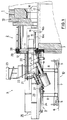
- FIG. 1 shows that part of a glass melting furnace 1 which is followed by the so-called dog house 2.
- dog house 2 These are known construction details of glass melting furnaces with a melting tank 3, so that there is no need to go into this detail further.
- An insertion device 4 abuts the dog house 2 and can be moved on rails 6 in the direction of the longitudinal axis of the oven by means of rollers 5.
- the castors 5 are height-adjustable on a base frame 7, which is connected via support columns 8 to a mounting platform 9, on which the parts and assemblies described in more detail below are attached.
- the base frame and assembly platform form the so-called movable frame 10, with which the insertion device 4 can be moved up to the insertion opening of the glass melting furnace.
- the dog house 2 has an insertion opening 11, which is closed by a heat shield 12 during melting operation of the furnace.
- the charging device 14 is designed as a vibration conveyor trough 13.
- the slider 16 is displaceable from the extended position shown in the position shown in dashed lines by the slider drive to be explained below.
- the slider 16 has a lower edge 16b which is submerged slightly below the molten bath surface 17 during the advance and in this position runs parallel to the molten bath surface.
- a charging chamber 20 is connected to it in a sealed manner, into which the vibrating conveyor trough 13 projects for most of its length.
- a funnel 22 is also passed through a ceiling 21 of the charging chamber 20 and is sealed, and its lower end projects into the vibrating conveyor trough 13.
- the upper end of the hopper 22 is connected to a batch container 23, of which only the lower end is shown.
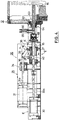
- the mounting platform 9 has longitudinal beams 24, on which both the charging chamber 20 and a housing 25 are arranged directly or indirectly, in which the slide drive 26 is located, which will be explained in more detail below .
- Modules located on the assembly platform 9 can be moved relative to the frame 10 in the longitudinal direction thereof by means of further castors 27. It can also be seen from FIG. 1 that the dog house 2 and the heat shield 12 are connected to one another via sealing packs 28 and 29, respectively.
- the slide drive 26 has two linearly acting drive units 30 and 31, which are arranged one above the other in tiers. Both drive units are pressure medium drives with piston rods 30a and 31a.
- the upper level of the slide drive 26 is omitted, or, the drive housing 25 was removed with its internals above a level EE.
- the drive unit 30 controls the axial movement of the slide carrier 15, and the drive unit 31 controls its rotational movement.
- the drive unit 30 controls the axial movement of the slide carrier 15, and the drive unit 31 controls its rotational movement.
- the slider 16 is off-center, that is attached to the slider carrier 15 via a bracket 33 and that this slider carrier has a circular cross section.
- the lower edge 16b of the slide 16 can now be lifted out of the glass melt and can be brought out of engagement with the molten bath surface 17 into a pivoted-up position.
- Two such possible swiveled-up positions are indicated by dash-dotted lines in FIG. 3, and it can be seen that the slide in the lowest position shown in broken lines can also be pulled out of the dog house 2 through the insertion opening 11 without bumping into any point.
- the vibrating conveyor trough 13 having a trough-shaped cross section is also shown in FIG. 3, as is the lower edge of the funnel 22 which projects into the vibrating conveyor trough 13. It goes without saying that the charging chamber 20 with the vibrating conveyor trough 13 is always withdrawn from the dog house together with the slide.
- the pivoting of the slide 16 illustrated in FIG. 3 is brought about by the linearly acting drive unit 31 shown in FIG. 4, the elongated piston rod 31a of which is initially stabilized by a longitudinal guide 34.
- the piston rod 31a is then connected to compensate for vertical transverse movements via a bracket 35 with a rigid angle lever 36, which is mounted in a fixed position on a bearing block 37 at its apex at a bearing point (not specified).
- the slide carrier 15 is also guided radially, but axially displaceable.
- One end of the angle lever 36 is now connected to an articulated bracket 38, the end of which is remote from the angle lever engages in a fork lever 39, the transmission of force to the slide carrier 15 is shown schematically in FIG. 5.
- the fork lever 39 is fastened to an outer sleeve 40, which first acts via a feather key 41 on an inner sleeve 42, which in turn transmits the applied torque to the slide carrier 15 via a further feather key 43.
- This arrangement creates the necessary degrees of freedom for the longitudinal displacement of the slide carrier 15 relative to the rotary drive.
- the pivot plane of the rigid angle lever 36 runs parallel to the axis of the linear movement or parallel to the drawing plane according to FIG. 4, but perpendicular to the drawing plane according to FIG. 2.
- the angle lever 36 acts on the fork lever 39 via an approximate tangential movement; the degrees of freedom required for a transverse movement are ensured by the presence of the joint plate 38.
- a slide carrier 15 and 45 are arranged on both sides of a vertical center plane MM of a modified insertion device 44, which are provided with slides 46 and 47 at their ends projecting into the dog house. Both sliders are shorter than the single slider 16 shown in FIG. 3, so that the ends 46a and 47a of the sliders 46 and 47 facing away from the slider supports 15 and 45 are not obstructed. When a feed movement is carried out, said ends 46a and 47a are directed towards one another, but only if synchronous feed movements are carried out.
- the two slide drives 26 and 48 are constructed and arranged mirror-symmetrically to the central plane M-M, including the drive housings 25 and 49 surrounding them.
- FIGS. 2 and 6 A comparison of FIGS. 2 and 6 in particular shows that the insertion devices 4 and 44 are of modular construction, ie insertion devices of this type can be converted or retrofitted in a simple manner.
- the insertion device 4 according to FIG. 2 can be expanded by replacing the slide 16 and additional attachment of a drive housing 49 with slide drive 48 and slide carrier 45 with slide 47.
- the charging chamber 20 and its built-in and superstructures as well as with regard to the vibrating conveyor trough 13 no changes are provided here.
- FIG. 7 shows the appearance of the parts of the insertion device 44 that protrude into the dog house 2.
- the slide 46 is designed in an analogous manner to the slide 16 in FIG. 3, but with a significantly shortened lower edge.
- the other slide 47 is mirror-symmetrical and arranged so that there is a distance between the ends 46a and 47a. In this case, too, the two sliders 46 and 47 can be pivoted into swiveled positions, which are shown in dash-dot lines in several possible positions.
- the structural elements of the charging device 14, which is also designed here as a vibrating conveyor trough 13, will be explained in more detail with reference to FIG. 8:
- the charging chamber 20 consists of a metallic outer jacket 50 with a heat-resistant ceramic lining 51.
- the heat shield 12 has a recess 52 in the region of the vibrating conveyor trough 13 for the passage of the vibrating conveyor trough 13, which is attached to the charging chamber 20 via inclined leaf springs 53.
- the charging chamber 20 has a first opening 54 for the passage of the vibration conveyor trough 13, which opening is essentially aligned with the recess 52 in the heat shield 12. At this point the charging chamber 20 is also connected to the heat shield.
- the charging chamber 20 has a second opening 55, which lies behind the cutting plane according to FIG. 8 and which is connected in a sealed manner via the funnel 22 to the batch container 23 (not shown here).
- a drive rod 57 of a charging drive 58 is guided through the bottom of the charging chamber 20 by means of an inclined pipe socket 56, which in the present case is designed as a vibration drive.
- the drive rod 57 is sealed off from the charging chamber 20 by a gland bushing 59, so that neither a gas outlet nor a gas inlet can take place at this point.
- the other end of the drive rod 57 is connected to the vibration conveyor trough 13.
- the vibration conveyor trough 13 is connected to the charging chamber 20 via a linear guide 60 parallel to the charging drive 58.
- This linear guide has a guide rod 61 which is also connected to the charging chamber 20 via a gland bushing 62.
- FIG. 4 shows that the slide carrier 15 is also sealed and passed through a bushing 63 in the heat shield 12. While in the prior art slot-shaped bushings had to be sealed by sliding plates, the bushing 63 in the subject of the invention is also sealed by a multi-stage stuffing box bushing 64, so that no undesired gas passage can occur at this point either. Cooling water flows through the slide carrier and the slide valves.
- the slide supports are double-walled or designed as concentric pipes and connected to a coolant circuit, not shown, via lateral connecting pieces 65 and 66.
- 64 insulating members 67 are arranged between the heat shield 12 and the gland bushing attached to it. Furthermore, a further insulating member 68 is arranged in the section of the slide carrier 15 lying outside the stuffing box bushing 64 and in front of the drive housing 25.
- the isolating members 67 and 68 pose no difficulties for the person skilled in the art; these insulating members serve for the galvanic separation of the parts of the charging device exposed to the melt from the prescribed ground potential.
- the connecting pieces 65 and 66 are also connected to the cooling water circuit via flexible and insulating hoses. These flexible connections also allow the required pivoting movement of the slide, which can be a maximum of about 90 degrees.
Landscapes
- Chemical & Material Sciences (AREA)
- Engineering & Computer Science (AREA)
- Materials Engineering (AREA)
- Organic Chemistry (AREA)
- Furnace Charging Or Discharging (AREA)
- Glass Melting And Manufacturing (AREA)
Applications Claiming Priority (2)
| Application Number | Priority Date | Filing Date | Title |
|---|---|---|---|
| DE4223184 | 1992-07-15 | ||
| DE19924223184 DE4223184C1 (de) | 1992-07-15 | 1992-07-15 | Verfahren und Vorrichtung zum Einlegen von Chargiermaterial in Glasschmelzöfen |
Publications (1)
| Publication Number | Publication Date |
|---|---|
| EP0579009A1 true EP0579009A1 (de) | 1994-01-19 |
Family
ID=6463204
Family Applications (1)
| Application Number | Title | Priority Date | Filing Date |
|---|---|---|---|
| EP93110083A Withdrawn EP0579009A1 (de) | 1992-07-15 | 1993-06-24 | Verfahren und Vorrichtung zum Einlegen von Chargiermaterial in Glasschmelzöfen |
Country Status (5)
| Country | Link |
|---|---|
| EP (1) | EP0579009A1 (cs) |
| JP (1) | JPH0789733A (cs) |
| CZ (1) | CZ130193A3 (cs) |
| DE (1) | DE4223184C1 (cs) |
| SK (1) | SK70793A3 (cs) |
Cited By (2)
| Publication number | Priority date | Publication date | Assignee | Title |
|---|---|---|---|---|
| DE102013217189A1 (de) * | 2013-08-28 | 2015-03-05 | Zippe Gmbh & Co. Kg | Einlegevorrichtung eines Glasschmelzofens |
| EP2894131A1 (de) * | 2014-01-13 | 2015-07-15 | ZIPPE GmbH & Co. KG | Einlegevorrichtung mit geschlossenem Förderelement |
Families Citing this family (1)
| Publication number | Priority date | Publication date | Assignee | Title |
|---|---|---|---|---|
| KR101908115B1 (ko) * | 2016-10-28 | 2018-10-15 | 울산과학기술원 | 전자펌프 |
Citations (3)
| Publication number | Priority date | Publication date | Assignee | Title |
|---|---|---|---|---|
| US2533826A (en) * | 1947-06-10 | 1950-12-12 | Hartford Empire Co | Apparatus for and method of charging batch to glass furnaces |
| US3587881A (en) * | 1968-10-28 | 1971-06-28 | Armstrong Cork Co | Glass furnace charger |
| DE3709178A1 (de) * | 1987-03-20 | 1988-09-29 | Sorg Gmbh & Co Kg | Einlegevorrichtung fuer glasschmelzoefen |
-
1992
- 1992-07-15 DE DE19924223184 patent/DE4223184C1/de not_active Expired - Fee Related
-
1993
- 1993-06-24 EP EP93110083A patent/EP0579009A1/de not_active Withdrawn
- 1993-06-29 CZ CZ931301A patent/CZ130193A3/cs unknown
- 1993-07-06 SK SK70793A patent/SK70793A3/sk unknown
- 1993-07-15 JP JP5175297A patent/JPH0789733A/ja active Pending
Patent Citations (3)
| Publication number | Priority date | Publication date | Assignee | Title |
|---|---|---|---|---|
| US2533826A (en) * | 1947-06-10 | 1950-12-12 | Hartford Empire Co | Apparatus for and method of charging batch to glass furnaces |
| US3587881A (en) * | 1968-10-28 | 1971-06-28 | Armstrong Cork Co | Glass furnace charger |
| DE3709178A1 (de) * | 1987-03-20 | 1988-09-29 | Sorg Gmbh & Co Kg | Einlegevorrichtung fuer glasschmelzoefen |
Cited By (3)
| Publication number | Priority date | Publication date | Assignee | Title |
|---|---|---|---|---|
| DE102013217189A1 (de) * | 2013-08-28 | 2015-03-05 | Zippe Gmbh & Co. Kg | Einlegevorrichtung eines Glasschmelzofens |
| DE102013217189B4 (de) | 2013-08-28 | 2017-03-30 | Zippe Gmbh & Co. Kg | Einlegevorrichtung eines Glasschmelzofens und Glasschmelzanlage |
| EP2894131A1 (de) * | 2014-01-13 | 2015-07-15 | ZIPPE GmbH & Co. KG | Einlegevorrichtung mit geschlossenem Förderelement |
Also Published As
| Publication number | Publication date |
|---|---|
| CZ130193A3 (en) | 1995-07-12 |
| DE4223184C1 (de) | 1993-10-28 |
| JPH0789733A (ja) | 1995-04-04 |
| SK70793A3 (en) | 1994-03-09 |
Similar Documents
| Publication | Publication Date | Title |
|---|---|---|
| DE3737563C2 (cs) | ||
| DE2853160C2 (de) | Vorrichtung zum Aufbringen von hitzebeständigem Material | |
| DE3928466C2 (de) | Beschickungsanlage für einen Schachtofen | |
| DE3101860C2 (cs) | ||
| EP2435375B1 (de) | Verfahren und vorrichtung zum beschicken von glas-schmelzöfen mit schüttfähigen glasgemengen | |
| DE2918762A1 (de) | Vorrichtung zum ueberziehen bzw. kandieren von koernigem gut | |
| DE3709178C2 (cs) | ||
| DE2929204A1 (de) | Beschickungsvorrichtung fuer schachtoefen | |
| DE3342572C2 (cs) | ||
| DE2703170A1 (de) | Vorrichtung zur herstellung von metallpulver | |
| WO1992011398A1 (de) | Lagerausbildung für die achsen oder achsverbindungen von getaucht in schmelzbädern rotierenden führungsrollen für bandförmiges behandlungsgut | |
| DE3530471C2 (cs) | ||
| DE2833615C2 (de) | Vorrichtung zum tiegelfreien Zonenschmelzen | |
| DE4223184C1 (de) | Verfahren und Vorrichtung zum Einlegen von Chargiermaterial in Glasschmelzöfen | |
| DE3115959A1 (de) | Verfahren zum schleifen von zahnraedern und vorrichtung zum durchfuehren des verfahrens | |
| EP0003247A1 (de) | Glasschmelzofen | |
| EP0262235B1 (de) | Vakuumplasmaspritzanlage | |
| DE69201494T2 (de) | Roboter, z.B. zum reinigen. | |
| EP0241740B1 (de) | Vorrichtung zur Entnahme von geschmolzenem Glas aus einer Schmelze | |
| DE3231225A1 (de) | Ofen zur waermebehandlung und durchfuehrung von waermeprozessen fuer werkstuecke aus eisenwerkstoffen und nichteisenmetallen | |
| DE3640144C2 (cs) | ||
| EP0664427B1 (de) | Schubrostkühler | |
| DE3125110C2 (de) | Schüttgutbunker-Austragvorrichtung | |
| DE2453057C2 (de) | Vorrichtung zur Verteilung von Gemenge auf der Oberfläche eines Glasschmelzofens | |
| DE4224127C1 (de) | Vorrichtung zum Einlegen von Chargiermaterial in Glasschmelzöfen |
Legal Events
| Date | Code | Title | Description |
|---|---|---|---|
| PUAI | Public reference made under article 153(3) epc to a published international application that has entered the european phase |
Free format text: ORIGINAL CODE: 0009012 |
|
| AK | Designated contracting states |
Kind code of ref document: A1 Designated state(s): AT BE CH DE DK ES FR GB IE IT LI NL PT SE |
|
| 17P | Request for examination filed |
Effective date: 19940708 |
|
| 17Q | First examination report despatched |
Effective date: 19960917 |
|
| GRAG | Despatch of communication of intention to grant |
Free format text: ORIGINAL CODE: EPIDOS AGRA |
|
| STAA | Information on the status of an ep patent application or granted ep patent |
Free format text: STATUS: THE APPLICATION HAS BEEN WITHDRAWN |
|
| 18W | Application withdrawn |
Withdrawal date: 19970919 |