EP0579104A1 - Dispositif de contrôle d'une eau de mouillage - Google Patents
Dispositif de contrôle d'une eau de mouillage Download PDFInfo
- Publication number
- EP0579104A1 EP0579104A1 EP93110892A EP93110892A EP0579104A1 EP 0579104 A1 EP0579104 A1 EP 0579104A1 EP 93110892 A EP93110892 A EP 93110892A EP 93110892 A EP93110892 A EP 93110892A EP 0579104 A1 EP0579104 A1 EP 0579104A1
- Authority
- EP
- European Patent Office
- Prior art keywords
- dampening water
- concentration
- ions
- etching solution
- information
- Prior art date
- Legal status (The legal status is an assumption and is not a legal conclusion. Google has not performed a legal analysis and makes no representation as to the accuracy of the status listed.)
- Ceased
Links
Images


Classifications
-
- B—PERFORMING OPERATIONS; TRANSPORTING
- B41—PRINTING; LINING MACHINES; TYPEWRITERS; STAMPS
- B41F—PRINTING MACHINES OR PRESSES
- B41F7/00—Rotary lithographic machines
- B41F7/20—Details
- B41F7/24—Damping devices
- B41F7/32—Ducts, containers, or like supply devices for liquids
-
- B—PERFORMING OPERATIONS; TRANSPORTING
- B41—PRINTING; LINING MACHINES; TYPEWRITERS; STAMPS
- B41F—PRINTING MACHINES OR PRESSES
- B41F33/00—Indicating, counting, warning, control or safety devices
- B41F33/0054—Devices for controlling dampening
-
- Y—GENERAL TAGGING OF NEW TECHNOLOGICAL DEVELOPMENTS; GENERAL TAGGING OF CROSS-SECTIONAL TECHNOLOGIES SPANNING OVER SEVERAL SECTIONS OF THE IPC; TECHNICAL SUBJECTS COVERED BY FORMER USPC CROSS-REFERENCE ART COLLECTIONS [XRACs] AND DIGESTS
- Y10—TECHNICAL SUBJECTS COVERED BY FORMER USPC
- Y10T—TECHNICAL SUBJECTS COVERED BY FORMER US CLASSIFICATION
- Y10T436/00—Chemistry: analytical and immunological testing
- Y10T436/11—Automated chemical analysis
- Y10T436/115831—Condition or time responsive
-
- Y—GENERAL TAGGING OF NEW TECHNOLOGICAL DEVELOPMENTS; GENERAL TAGGING OF CROSS-SECTIONAL TECHNOLOGIES SPANNING OVER SEVERAL SECTIONS OF THE IPC; TECHNICAL SUBJECTS COVERED BY FORMER USPC CROSS-REFERENCE ART COLLECTIONS [XRACs] AND DIGESTS
- Y10—TECHNICAL SUBJECTS COVERED BY FORMER USPC
- Y10T—TECHNICAL SUBJECTS COVERED BY FORMER US CLASSIFICATION
- Y10T436/00—Chemistry: analytical and immunological testing
- Y10T436/12—Condition responsive control
Definitions
- This invention relates to an apparatus for controlling dampening water circulatively used in offset printers. More particularly, it is concerned with an improvement in a dampening water controller or controlling apparatus for controlling the concentration of etching solution in dampening water containing an alcohol or surface active agent and an etching solution as well as impurities such as ink and paper dust that can be brought into the dampening water as it is used circulatively.
- dampening water In offset printing, what is called dampening water is usually made to adhere to non-image areas on which no ink must be laid, to cause that areas to repel ink so that the ink can be controlled to adhere or not to adhere according to a pattern on a plate. Accordingly, how the the dampening water is maintained and controlled to function at a high performance is a very important subject for the quality of prints obtained by offset printing.
- the dampening water usually contains water, an etching solution (a solution added to dampening water when used) and an alcohol such as isopropyl alcohol or ethyl alcohol or a surface active agent.
- the alcohol or surface active agent though contained in a trace amount, decreases the surface tension of the dampening water to thereby improve its wettability to a plate and so functions as to uniformly spread the dampening water over the whole plate. That is, the alcohol or surface active agent contained in an appropriate amount greatly contributes a fundamental performance of the offset printing.
- the etching solution also contains gum arabic, which is a colloidal substance comprised of a water-soluble polymer.
- the gum arabic has what is called a desensitizing action. This desensitizing action is greatly affected by pH values, and is considered to exhibit its highest function in a certain specific pH range. For this reason, anions such as nitrate ions, nitrite ions, phosphate ions, fluoride ions, chloride ions, sulfate ions or sulfide ions or cations such as sodium ions, ammonium ions, calcium ions or potassium ions are usually mixed in the etching solution. Using these various kinds of ions and a pH adjuster optionally added, the pH value of the dampening water containing the etching solution is adjusted so as to be set in a specific pH range, usually in a pH range of from 4.0 to 6.5.
- the concentration (%) of etching solution in the dampening water is defined as: 100Y/(X+Y+Z) (%) wherein X represents a quantity of water before the mixing of a stock solution of the etching solution, Y represents a quantity of a stock solution of the etching solution, and Z represents a quantity of an alcohol.
- concentration (%) of alcohol in the dampening water it is defined as follows: 100Z/(X+Y+Z) (%)
- An object thereof is to provide a dampening water controller that can control the concentration of etching solution in dampening water in a high precision and can maintain the concentration of etching solution in dampening water at a proper degree.
- Another object of the present invention is to provide a dampening water controller that can control the concentration of etching solution in dampening water in a high precision and also can perform maintenance of the apparatus with ease.
- the present invention provides a dampening water controller for controlling the concentration of an etching solution in dampening water circulatively used in offset printing, comprising; an ion concentration measuring means capable of measuring the concentration of anions or cations contained in the etching solution in said dampening water; said anions being selected from the group consisting of nitrate ions, nitrite ions, phosphate ions, fluoride ions, sulfate ions and sulfide ions and said cations being selected from the group consisting of sodium ions, ammonium ions and potassium ions; and outputting information on the measured concentration of the ions in the dampening water; a dampening water temperature measuring means capable of measuring the temperature of said dampening water and outputting information on the measured temperature; an ion concentration information correcting means capable of correcting the information on the measured concentration of the ions in the dampening water, in accordance with the information on the measured temperature of the dampening water; and an etching solution concentration adjusting means
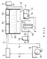
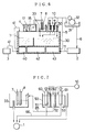
- Fig. 1 schematically illustrates the construction of a dampening water controller according to Example 1 of the present invention.
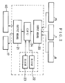
- Fig. 2 is a block diagram to show control means of the dampening water controller according to Example 1.
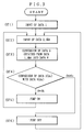
- Fig. 3 is a flow chart to show operating steps of the dampening water controller according to Example 1.
- Fig. 4 schematically illustrates the construction of a dampening water controller according to Example 2 of the present invention.
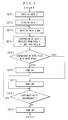
- Fig. 5 is a flow chart to show operating steps of the dampening water controller according to Example 2.
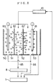
- Fig. 6 schematically illustrates the construction of a dampening water controller according to Example 3 of the present invention.
- Fig. 7 schematically illustrates a part of Fig. 6 in more detail.
- Fig. 8 schematically illustrates an ion separation chamber of the dampening water controller according to Example 3.
- Fig. 9 schematically illustrates the construction of a dampening water controller according to Example 4 of the present invention.
- Fig. 10 schematically illustrates an ion separation chamber of the dampening water controller according to Example 4.
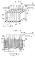
- Fig. 11 schematically illustrates an ion separation chamber of the dampening water controller according to Example 5.
- Fig. 12 schematically illustrates an ion separation chamber of the dampening water controller according to Example 6.
- the dampening water controller of the present invention will first be generically described below.
- the dampening water controller of the present invention basically has an ion concentration measuring means capable of measuring the concentration of specific anions or cations contained in an etching solution in dampening water, and outputting information on the measured concentration of the ions in the dampening water; a dampening water temperature measuring means capable of measuring the temperature of the dampening water and outputting information on the measured temperature; an ion concentration information correcting means capable of correcting the information on the measured concentration of the ions in the dampening water, in accordance with the information on the measured temperature of the dampening water; and an etching solution concentration adjusting means capable of adjusting the concentration of the etching solution in the dampening water, in accordance with the corrected information on the ion concentration.
- the dampening water controller of the present invention which takes note of specific ions (herein also called "object ions") in dampening water, is provided with means for well precisely detecting the concentration of object ions in the dampening water, judging whether or not the concentration of an etching solution is in a proper state, and, if not, making adjustment so that it is brought into a proper state. Also taking account of the fact that measured data are variable depending on changes in temperature of the dampening water serving as a sample for examination, the controller of the present invention is also provided with mean for correcting the measured data in accordance with information on dampening water temperature monitored at the same time during the use of the dampening water, to better precisely determine the concentration of object ions, and for making the above judgement and adjustment.
- object ions specific ions
- the dampening water controller of the present invention may be replaced with the construction in which a means for converting the corrected information on the concentration of object ions into information on the concentration of etching solution in the dampening water is added so that the concentration of etching solution in the dampening water is adjusted in accordance with the information on the concentration of the etching solution.
- a means for displaying the information on the concentration of the etching solution may also be added.
- the object ions are not ions originating from water, impurities, a pH adjuster, etc., but ions contained in only the etching solution.
- ions preferable as the object ions ions contained in the largest quantity and on which ion concentration can be readily determined are exemplified by nitrate ions (NO3 ⁇ ).
- object ions that may be used in place of the nitrate ions or may be used in combination in addition to the nitrate ions may include anions appropriately selected from nitrite ions (NO2 ⁇ ), phosphate ions (PO43 ⁇ ), fluoride ions (F ⁇ ), sulfate ions (SO42 ⁇ ) and sulfide ions (S2 ⁇ ) and cations appropriately selected from sodium ions (Na+), ammonium ions (NH4+) and potassium ions (K+).
- NO2 ⁇ nitrite ions
- PO43 ⁇ phosphate ions
- F ⁇ fluoride ions
- SO42 ⁇ sulfate ions
- S2 ⁇ sulfide ions
- cations appropriately selected from sodium ions (Na+), ammonium ions (NH4+) and potassium ions (K+).
- the indirect means may include what is called the ion-selective electrode method (JIS K0122).
- JIS K0122 the ion-selective electrode method
- a given ion-selective electrode responds to the object ions to be measured, in a measuring system of "reference electrode/solution to be examined/ion-selective electrode", and produces a potential difference corresponding to ionic activities according to the Nernst equation.
- an impurity separation means may be added to the system so that the lifetime of the electrode can be elongated, which is a means for removing impurities brought into the dampening water and feeding the resulting impurities-free water to the zone corresponding to the ion concentration measuring means.
- a cation separation means may also be added to the system so that electrodes can be prevented from deteriorating with occurrence of deposits on the surface of the electrode on the cathode side, which is a means for separating only cations from the dampening water serving as a sample for examination, and feeding the resulting cations-free dampening water to the zone corresponding to the ion concentration measuring means.
- the dampening water controller according to the present invention can also bring about desirable results also when used in combination with a dampening water controller different from the present invention, e.g., a dampening water controller in which the alcohol concentration previously described in relation to the prior art is monitored and its concentration is controlled.
- the concentration of at least one kind of ions selected from the specific anions and cations contained in only the etching solution of the dampening water circulatively used is measured, and the concentration of etching solution in the dampening water is controlled in accordance with the information on this ion concentration.
- this dampening water controller comprises a monitoring tank 33 in which dampening water 30 fed from a dampening water tank 1 is stored, a nitrate ion concentration sensor 8 and a dampening water temperature sensor 7 which are provided in the monitoring tank 33, and a control means 4 into which information from each sensor is inputted to make control of the dampening water. These constitute the main part of the dampening water.
- the dampening water 30 stored in the dampening water tank 1 is sent to a water fountain 31 provided therein with a water fountain roller 32, through a water feed pipe 5 by means of a circulating pump 43, where it is led to rollers of a printer.
- the water fountain 31 is so designed for the dampening water 30 to be kept in a given liquid quantity.
- the dampening water 30 having been not consumed in the printer is circulated into the dampening water tank 1 through a water return pipe 6, a dampening water subtank 2, a subtank discharge pipe 11, the circulation pump 43 and a cooler 42.
- the dampening water 30 is circulated in this way, and hence ink and paper dust or fine fragments of printing paper are brought into it as impurities as previously stated.
- a stock solution of the etching solution is stored in an etching solution reservoir 3.
- the etching solution is fed into the dampening water tank 1 in an appropriate quantity from the etching solution reservoir 3 through an etching solution feed pipe 41 by means of an etching solution feed pump 40.
- the above monitoring tank 33 is so constructed that the dampening water 30 is fed into it through a water feed branch pipe 10 partly branched from the water feed pipe 5 and also its water level can be always kept constant.
- a nitrate ion concentration sensor 8 comprised of a liquid membrane type ion-selective electrode and a reference electrode is immersed as an etching solution concentration measuring means, and also a dampening water temperature sensor 7 is immersed as the dampening water temperature measuring means that measures the temperature of the dampening water 30.
- the nitrate ion concentration sensor 8 measures the concentration of nitrate ions in the dampening water 30 to which the etching solution has been added, utilizing as a basis an electromotive force produced across the electrodes, and outputs information on the etching solution concentration to the control means 4.
- the dampening water temperature sensor 7 measures the temperature of the dampening water 30 and outputs temperature information for correcting the information on the nitrate ion concentration, to the control means 4.
- the above control means 4 is constituted of a microcomputer system as shown in Fig. 2, whose main part is comprised of an input means 20, a CPU 24 that controls the whole system, a RAM 23 into and from which data are written and read from the CPU 24, and ROM 22 having been programmed with instructions as shown in Fig. 3 in the form of a flow chart, and an output means 21.
- correction data based on a characteristic diagram showing the relationship between the concentration of nitrate ions contained in the dampening water 30 and the temperature of the dampening water 30, and the relationship between the nitrate ion concentration and the etching solution concentration are stored in the form of a table. These correction data are obtained from measured data set previously.
- calibration information on the nitrate ion concentration (DATA 1), a value set on an external switch 15 for setting the etching solution concentration (DATA 2), which is a threshold value used as a standard concentration d b on the basis of which the concentration of etching solution in the dampening water 30 is controlled, are inputted through the input means 20.
- Information on the ion concentration in the dampening water 30 (DATA 3) and information on the temperature of the dampening water 30 (DATA 4) are also temporarily stored in it (see ST1 to AT 2 in Fig. 3).
- the calibration information on the nitrate ion concentration is meant to be information obtained in order to previously ascertain the response, etc.
- etching solution concentrations of calibration solutions having a predetermined etching solution concentration e.g., a calibration solution with an etching solution concentration of 3% and a calibration solution with an etching solution concentration of 0% are used
- concentration of nitrate ions contained in the etching solution in the dampening water 30 serving as a sample for examination is measured, as in commonly available measuring apparatus in various fields.
- the operation as shown below is carried out on the bases of the information stored in the RAM 23 and the information stored in the ROM 22.
- the CPU 24 calibrates the information on the actually measured nitrate ion concentration in the dampening water 30 (DATA 3) in accordance with the calibration information on the nitrate ion concentration (DATA 1). It also corrects variations in the nitrate ion concentration on the dampening water 30 in accordance with the information on the temperature of the dampening water 30 (DATA 4). Thus, a corrected nitrate ion concentration of the dampening water 30 (DATA 5) is obtained.
- the CPU 24 converts the corrected nitrate ion concentration of the dampening water 30 (DATA 5) into an etching solution concentration d x and handles it as information on the etching solution concentration (DATA 6) (see ST3 in Fig. 3).
- the CPU 24 compares the etching solution concentration d x with the standard concentration d b having been set and inputted through the etching solution concentration setting switch 15 to judge their relationship of high-low fluctuation (see ST4 in Fig. 3).
- the output means 21 outputs signals for PUMP ON or PUMP OFF to the etching solution feed pump 40 in accordance with the results of the judgment.
- the etching solution feed pump 40 is driven (see ST5 in Fig. 3) and the stock solution of the etching solution is fed into the dampening water tank 1, so that the quantity of the etching solution contained in the dampening water 30 increases.
- the etching solution feed pump 40 is stopped (see ST6 in Fig. 3) and the stock solution of the etching solution is stopped being fed into the dampening water tank 1.
- the etching solution concentration d x in the dampening water 30 becomes higher than the standard concentration d b used for control. If, however, this has occurred, the system is so set up as to make an alarm signal from an alarm system (not shown) to give attention to an operator.
- a consumed etching solution is compensated while continually repeating this control process, so that the etching solution concentration in the dampening water 30 is made close to the standard concentration used for control and the etching solution concentration in the dampening water 30 is substantially kept constant.
- Corrected values of the etching solution concentration in the dampening water 30 and the information on the temperature of the dampening water 30 are digitally displayed on a display device 17.
- the present apparatus automatically repeats the processing described above.
- an operator can stop it at arbitrary timing by, for example, operating a stop switch or giving a stop command.
- the dampening water controller according to this Example is substantially the same as the dampening water controller according to Example 1 except that, as shown in Fig. 4, a filter 34 serving as the impurity separation means is provided in the course of the water feed branch pipe 10.
- the dampening water 30 is fed through the water feed branch pipe 10.
- This apparatus is so designed that impurities such as ink and paper dust are separated from the dampening water 30 by the action of this filter 34 and the resulting impurities-free dampening water 30 is sent to the monitoring tank 33.
- the filter 34 used in this apparatus is WIND CARTRIDGE CS (trade name; available from Nihon Filter Co., Ltd.) having a pore size of about 50 ⁇ m to about 100 ⁇ m.
- the dampening water 30 having been monitored is returned to the dampening water tank 1 through the monitoring tank 33.
- the ROM 22 that constitutes part of the control means 4 (see Fig. 2) of this apparatus has been programmed with instructions as represented by a flow chart (see Fig. 5) more detailed than that in Fig. 3. More specifically, in this apparatus, like the dampening water according to Example 1, a calibration value obtained from a calibration solution (i) (city water) with an etching solution concentration of 0% (DATA 1') is measured by means of the nitrate ion concentration sensor 8 comprised of an ion-selective electrode and a reference electrode and is stored in the memory (see ST1 in Fig.
- the dampening water controller according to this Example is substantially the same as the dampening water controller according to Example 1 except that, as shown in Fig. 6, an ion separation chamber 50 is provided between the water feed pipe 5 and the monitoring tank 33.
- the ion separation chamber 50 comprises, as shown in Figs. 7 to 8, a cation-selective electrode chamber 51 partitioned with two cation-exchange membranes 62 and 62' (trade name: SELEMION; cation-exchange membranes available from Asahi Glass Co., Ltd.), a dampening water anionic solution chamber 52 and an anion-selective electrode chamber 53. These constitute the main part of the ion separation chamber.
- An anode plate 60 is also provided in the cation-selective electrode chamber 51, and an cathode plate 61 in the anion-selective electrode 53.
- the dampening water 30 serving as a sample for examination is fed into each of these cation-selective electrode chamber 51, dampening water anionic solution chamber 52 and anion-selective electrode chamber 53 through the water feed branch pipe 10.
- the dampening water 30 fed into the dampening water anionic solution chamber 52 the cations in the dampening water 30 pass through the cation-exchange membrane 62', attracted to the cathode plate 61 of the anion-selective electrode chamber 53, and removed from the chamber 52.
- the anions in the dampening water 30 are attracted to the cathode plate 60 of the cation-selective electrode chamber 51, but can not pass through the cation-exchange membrane 62, and hence the dampening water 30 from which only cations have been removed remains in the chamber 52.
- the dampening water 30 fed into the cation-selective electrode chamber 51 its anions are attracted to the anode plate 60, but on the other hand the cations in the dampening water 30 are repelled therefrom and some of them pass through the cation-exchange membranes 62 and 62' and are attracted to the cathode plate 61 of the anion-selective electrode chamber 53.
- dampening water 30 in the dampening water anionic solution chamber 52 is fed into the monitoring tank 33 through a dampening water anionic solution feed pipe 65, and the nitrate ion concentration in the dampening water 30 fed thereinto is measured by the nitrate ion concentration sensor 8.
- the dampening water 30 held in the cation-selective electrode chamber 51 and anion-selective electrode chamber 53 is again returned to the dampening water tank 1 through an ionic solution return pipe 66, and the dampening water 30 having been monitored is also returned to the dampening water tank 1 through the monitoring tank 33.
- the dampening water controller according to this Example is substantially the same as the dampening water controller according to Example 3 except that, as shown in Figs. 9 and 10, the dampening water 30 is fed into the ion separation chamber 50 from its bottom side and also the dampening water 30 from which cations have been removed is fed into the monitoring tank 33 from the top side of the chamber.
- the dampening water controller according to this Example is substantially the same as the dampening water controller according to Example 3 except that, as shown in Fig. 11, the ion separation chamber 50 is mainly comprised of a cation-selective electrode chamber 51 partitioned with a plurality of cation-exchange membranes (trade name: NEOSEPTA; cation-exchange membranes available from Tokuyama Soda Co., Ltd.) 62, a plurality of dampening water anionic solution chambers 52 and an anion-selective electrode chamber 53, the dampening water 30 is fed into the ion separation chamber 50 from its bottom side, and also the dampening water 30 from which cations have been removed is fed into the monitoring tank 33 from the top side of the chamber through a dampening water anionic solution feed pipe 65.
- a cation-selective electrode chamber 51 partitioned with a plurality of cation-exchange membranes (trade name: NEOSEPTA; cation-exchange
- dampening water controller according to this Example also, no cations are contained in the dampening water 30 fed into the monitoring tank 33, and hence it becomes possible to elongate the lifetime of the ion-selective electrodes, etc. compared with the dampening water controller according to Example 1, bringing about the advantage that the maintenance of the apparatus can be made easier.
- the ion separation chamber 50 is provided with a plurality of dampening water anionic solution chamber 52, the cations in the dampening water can be separated in a shorter time and in a larger quantity.
- the dampening water controller according to this Example is substantially the same as the dampening water controller according to Example 3 except that, as shown in Fig. 12, the ion separation chamber 50 is comprised of a group of ion separation chambers each comprising a cation-selective electrode chamber 51 partitioned with two cation-exchange membranes 62 and 62, a dampening water anionic solution chamber 52 and an anion-selective electrode chamber 53, the dampening water is fed into the ion separation chamber 50 from its bottom side, and also the dampening water from which cations have been removed is fed into the monitoring tank from the top side of the chamber through a dampening water anionic solution feed pipe 65.
- An anode plate 60 is provided in each cation-selective electrode chamber 51, and a cathode plate 61 in each anion-selective electrode chamber 53.
- the dampening water controller according to this Example also, no cations are contained in the dampening water 30 fed into the monitoring tank 33, and hence it becomes possible to elongate the lifetime of the ion-selective electrodes, etc. compared with the dampening water controller according to Example 1, bringing about the advantage that the maintenance of the apparatus can be made easier.
- the ion separation chamber 50 is comprised of a plurality of ion separation chambers, the cations in the dampening water can be separated in a shorter time and in a larger quantity than in the dampening water controller according to Example 5.
- the dampening water controller of the present invention comprises an ion concentration measuring means capable of measuring the concentration of at least one kind of ions (object ions) selected from specific anions or cations contained only in an etching solution in dampening water, and outputting information on the measured concentration of the ions in the dampening water; a dampening water temperature measuring means capable of measuring the temperature of the dampening water and outputting information on the measured temperature; an ion concentration information correcting means capable of correcting the information on the measured concentration of the ions in the dampening water, in accordance with the information on the measured temperature of the dampening water; and an etching solution concentration adjusting means capable of adjusting the concentration of the etching solution in the dampening water, in accordance with the corrected information on the ion concentration.
- an ion concentration measuring means capable of measuring the concentration of at least one kind of ions (object ions) selected from specific anions or cations contained only in an etching solution in dampening water, and outputting information on the measured
- the present dampening water controller can have less influence from the impurities such as ink and paper dust brought into the dampening water, and can control the concentration of the etching solution in a much higher precision.
- the present invention is effective for producing high-quality offset prints in a large quantity and with ease.
- a dampening water controller for controlling the concentration of an etching solution in dampening water circulatively used in offset printing comprises an ion concentration measuring means capable of measuring the concentration of at least one kind of ions (object ions) selected from specific anions or cations contained only in an etching solution in dampening water, and outputting information on the measured concentration of the ions in the dampening water; a dampening water temperature measuring means capable of measuring the temperature of the dampening water and outputting information on the measured temperature; an ion concentration information correcting means capable of correcting the information on the measured concentration of the ions in the dampening water, in accordance with the information on the measured temperature of the dampening water; and an etching solution concentration adjusting means capable of adjusting the concentration of the etching solution in the dampening water, in accordance with the corrected information on the ion concentration.
- This dampening water controller controls the concentration of the etching solution by measuring the concentration of the object ions contained only in the etching solution in the dampening water.
- the present dampening water controller can have less influence from the impurities such as ink and paper dust brought into the dampening water, and can control the concentration of the etching solution in a much higher precision.
- the present invention is effective for producing high-quality offset prints in a large quantity and with ease.
Landscapes
- Engineering & Computer Science (AREA)
- Mechanical Engineering (AREA)
- Rotary Presses (AREA)
- Inking, Control Or Cleaning Of Printing Machines (AREA)
Applications Claiming Priority (6)
| Application Number | Priority Date | Filing Date | Title |
|---|---|---|---|
| JP180835/92 | 1992-07-08 | ||
| JP18083592 | 1992-07-08 | ||
| JP268451/92 | 1992-10-07 | ||
| JP26845192 | 1992-10-07 | ||
| JP66803/93 | 1993-03-25 | ||
| JP6680393 | 1993-03-25 |
Publications (1)
| Publication Number | Publication Date |
|---|---|
| EP0579104A1 true EP0579104A1 (fr) | 1994-01-19 |
Family
ID=27299250
Family Applications (1)
| Application Number | Title | Priority Date | Filing Date |
|---|---|---|---|
| EP93110892A Ceased EP0579104A1 (fr) | 1992-07-08 | 1993-07-07 | Dispositif de contrôle d'une eau de mouillage |
Country Status (2)
| Country | Link |
|---|---|
| US (1) | US5368817A (fr) |
| EP (1) | EP0579104A1 (fr) |
Cited By (2)
| Publication number | Priority date | Publication date | Assignee | Title |
|---|---|---|---|---|
| DE29705673U1 (de) * | 1997-03-29 | 1997-05-15 | Technotrans GmbH, 48336 Sassenberg | Vorrichtung zur Messung und Einstellung des Alkoholgehalts im Feuchtmittel für den Offsetdruck |
| EP1743769A3 (fr) * | 2005-06-24 | 2009-07-01 | Technotrans AG | Machine d'impression avec un appareil périphérique |
Families Citing this family (6)
| Publication number | Priority date | Publication date | Assignee | Title |
|---|---|---|---|---|
| US5826514A (en) * | 1995-10-19 | 1998-10-27 | Technicas Especiales De Oxigenacion, S.L. | Introduced in wetting systems for offset printing and a mechanism for their application |
| DE19546260C1 (de) * | 1995-12-12 | 1996-11-21 | Weitmann & Konrad Fa | Verfahren zur Überwachung der Sprühmenge einer zur Befeuchtung bewegter Materialbahnen in die Breite versprühten Flüssigkeit über deren Breite, Vorrichtung zur Durchführung des Verfahrens, sowie Verwendung der Vorrichtung |
| DE19607681B4 (de) * | 1996-02-29 | 2009-07-09 | Fogra Forschungsgesellschaft Druck E.V. | Verfahren und Vorrichtung zur kontinuierlichen Messung und Regelung der Zusammensetzung einer Feuchtmittellösung für den Offsetdruck |
| US5826507A (en) * | 1997-05-22 | 1998-10-27 | Union Camp Corporation | Method for measuring the amount of fountain solution in offset lithography printing |
| DE19929844A1 (de) * | 1999-06-29 | 2001-01-04 | Baldwin Grafotec Gmbh | Flüssigkeits-Versorgungsvorrichtung |
| DE10152466B4 (de) * | 2000-11-24 | 2015-12-17 | Heidelberger Druckmaschinen Ag | Feuchteregelung unter Berücksichtigung mehrerer den Druckprozess beeinflussender Größen |
Citations (7)
| Publication number | Priority date | Publication date | Assignee | Title |
|---|---|---|---|---|
| EP0170160A2 (fr) * | 1984-08-01 | 1986-02-05 | WEB ITALIA S.r.l. | Installation d'alimentation en solution de mouillage pour l'impression offset |
| EP0227949A2 (fr) * | 1985-11-26 | 1987-07-08 | Dai Nippon Insatsu Kabushiki Kaisha | Dispositif pour régler la concentration d'une solution aqueuse d'alcool |
| JPS62172244A (ja) * | 1986-01-27 | 1987-07-29 | Hitachi Ltd | 溶剤と弗化水素との混合液の濃度測定方法 |
| JPS631543A (ja) * | 1986-06-23 | 1988-01-06 | Dainippon Printing Co Ltd | 印刷用湿し水の組成管理装置 |
| GB2206413A (en) * | 1987-04-22 | 1989-01-05 | Univ Manchester | Determining a component in an organic solvent containing solution |
| DE3822344A1 (de) * | 1988-07-01 | 1990-01-04 | Captron Elect Gmbh | Vorrichtung zum messen von das dielektrische verhalten beeinflussenden eigenschaften einer fluessigkeit |
| EP0378497A1 (fr) * | 1989-01-13 | 1990-07-18 | Alain Zanon | Dispositif pour le contrôle et la régulation de l'eau de mouillage dans un système d'impression offset |
Family Cites Families (6)
| Publication number | Priority date | Publication date | Assignee | Title |
|---|---|---|---|---|
| US4388864A (en) * | 1978-12-11 | 1983-06-21 | Warner "Autolitho" Corporation | Lithographic dampening system |
| EP0220350A1 (fr) * | 1985-10-22 | 1987-05-06 | British Nuclear Fuels PLC | Analyse de concentration d'ions |
| GB8522126D0 (en) * | 1985-09-06 | 1985-10-09 | Tytronics Inc | Sample monitoring arrangement |
| US4814281A (en) * | 1986-01-07 | 1989-03-21 | Westinghouse Electric Corp. | Differential conductivity sulfate monitor |
| JP2504596Y2 (ja) * | 1990-01-26 | 1996-07-10 | 富士写真フイルム株式会社 | 湿し水自動補充装置 |
| US5102520A (en) * | 1990-10-31 | 1992-04-07 | Behr Omri M | Electrolytic etching process and apparatus |
-
1993
- 1993-07-02 US US08/085,158 patent/US5368817A/en not_active Expired - Fee Related
- 1993-07-07 EP EP93110892A patent/EP0579104A1/fr not_active Ceased
Patent Citations (7)
| Publication number | Priority date | Publication date | Assignee | Title |
|---|---|---|---|---|
| EP0170160A2 (fr) * | 1984-08-01 | 1986-02-05 | WEB ITALIA S.r.l. | Installation d'alimentation en solution de mouillage pour l'impression offset |
| EP0227949A2 (fr) * | 1985-11-26 | 1987-07-08 | Dai Nippon Insatsu Kabushiki Kaisha | Dispositif pour régler la concentration d'une solution aqueuse d'alcool |
| JPS62172244A (ja) * | 1986-01-27 | 1987-07-29 | Hitachi Ltd | 溶剤と弗化水素との混合液の濃度測定方法 |
| JPS631543A (ja) * | 1986-06-23 | 1988-01-06 | Dainippon Printing Co Ltd | 印刷用湿し水の組成管理装置 |
| GB2206413A (en) * | 1987-04-22 | 1989-01-05 | Univ Manchester | Determining a component in an organic solvent containing solution |
| DE3822344A1 (de) * | 1988-07-01 | 1990-01-04 | Captron Elect Gmbh | Vorrichtung zum messen von das dielektrische verhalten beeinflussenden eigenschaften einer fluessigkeit |
| EP0378497A1 (fr) * | 1989-01-13 | 1990-07-18 | Alain Zanon | Dispositif pour le contrôle et la régulation de l'eau de mouillage dans un système d'impression offset |
Non-Patent Citations (2)
| Title |
|---|
| PATENT ABSTRACTS OF JAPAN vol. 012, no. 016 (P - 656) 10 January 1988 (1988-01-10) * |
| PATENT ABSTRACTS OF JAPAN vol. 012, no. 195 (M - 705) 7 June 1988 (1988-06-07) * |
Cited By (2)
| Publication number | Priority date | Publication date | Assignee | Title |
|---|---|---|---|---|
| DE29705673U1 (de) * | 1997-03-29 | 1997-05-15 | Technotrans GmbH, 48336 Sassenberg | Vorrichtung zur Messung und Einstellung des Alkoholgehalts im Feuchtmittel für den Offsetdruck |
| EP1743769A3 (fr) * | 2005-06-24 | 2009-07-01 | Technotrans AG | Machine d'impression avec un appareil périphérique |
Also Published As
| Publication number | Publication date |
|---|---|
| US5368817A (en) | 1994-11-29 |
Similar Documents
| Publication | Publication Date | Title |
|---|---|---|
| DE69227343T2 (de) | Vorrichtung zur Kontrolle einer Entwicklerlösung | |
| DE68916771T2 (de) | Bestimmen und Überwachen von Parametern in Kesselanlagen. | |
| US5368817A (en) | Dampening water controller | |
| DE69302315T2 (de) | Methode und Vorrichtung zur Aufrechterhaltung einer Lösung zur stromlosen Metallisierung | |
| WO1997018503A1 (fr) | Dispositif et procede d'ajustement de concentrations ioniques | |
| DE2837219C2 (fr) | ||
| US3839162A (en) | Method and apparatus for the determination of the concentration of relevant ions in aqueous solutions | |
| DE3736230C1 (de) | Verfahren und Einrichtung zur selektiven Bestimmung des Gehaltes eines in einem Loesungsmittel geloesten Stoffes | |
| DE3689168T2 (de) | Vorrichtung zur Regulierung der Konzentration einer wässrigen Alkohollösung. | |
| EP2169392B1 (fr) | Procédé et dispositif destinés à la mesure de la dureté de l'eau | |
| DE69910315T2 (de) | Elektrolytische Rückgewinnung von Metall aus einer Lösung | |
| US20060260954A1 (en) | Acidic electrolyzed water production system and generation control method | |
| DE69214455T2 (de) | Verwendung einer pH-empfindlichen Referenz-Elektrode für die elektrolytische Entsilberung | |
| DE1243898B (de) | Verfahren und Vorrichtung zur automatischen analytischen Pruefung von Fluessigkeiten | |
| DE2606892C2 (fr) | ||
| DE69117723T2 (de) | Verfahren und vorrichtung zur steuerung der konzentration für fällungsreaktionen | |
| DE69322850T2 (de) | Sauerstoffanalysegerät | |
| EP2335941B1 (fr) | Réglage de dureté par agent d'humification | |
| DE3546409A1 (de) | Verfahren und vorrichtung zur selbsttaetigen kalibrierung von chemischen sensoren | |
| JP3248303B2 (ja) | 湿し水管理装置 | |
| JP3381379B2 (ja) | エッチ液濃度測定装置 | |
| DE3433618C2 (de) | Verfahren und Vorrichtung zur Regelung der Fällungsmittelzufuhr bei der Schwermetallfällung | |
| DE3743428A1 (de) | Verfahren zum konditionieren und entwaessern von schlaemmen | |
| EP0625592A1 (fr) | Procédé et dispositif pour la récupération électrolytique d'argent dans deux machines de traitement de films | |
| DE69121023T2 (de) | Verfahren und System zur kontinuierlichen Überwachung und Regelung von Entchlorisierungsrückständen in einem Prozesstrom |
Legal Events
| Date | Code | Title | Description |
|---|---|---|---|
| PUAI | Public reference made under article 153(3) epc to a published international application that has entered the european phase |
Free format text: ORIGINAL CODE: 0009012 |
|
| AK | Designated contracting states |
Kind code of ref document: A1 Designated state(s): DE FR GB NL |
|
| 17P | Request for examination filed |
Effective date: 19940704 |
|
| GRAG | Despatch of communication of intention to grant |
Free format text: ORIGINAL CODE: EPIDOS AGRA |
|
| 17Q | First examination report despatched |
Effective date: 19960219 |
|
| STAA | Information on the status of an ep patent application or granted ep patent |
Free format text: STATUS: THE APPLICATION HAS BEEN REFUSED |
|
| 18R | Application refused |
Effective date: 19960816 |