EP0579181A1 - Unité de commande centrale pour des supports de positionnement contrôlables d'un véhicule de lutte contre l'incendie équipé d'une échelle tournante ou analogue - Google Patents
Unité de commande centrale pour des supports de positionnement contrôlables d'un véhicule de lutte contre l'incendie équipé d'une échelle tournante ou analogue Download PDFInfo
- Publication number
- EP0579181A1 EP0579181A1 EP93111222A EP93111222A EP0579181A1 EP 0579181 A1 EP0579181 A1 EP 0579181A1 EP 93111222 A EP93111222 A EP 93111222A EP 93111222 A EP93111222 A EP 93111222A EP 0579181 A1 EP0579181 A1 EP 0579181A1
- Authority
- EP
- European Patent Office
- Prior art keywords
- control unit
- driver
- vehicle
- hydraulic
- cab
- Prior art date
- Legal status (The legal status is an assumption and is not a legal conclusion. Google has not performed a legal analysis and makes no representation as to the accuracy of the status listed.)
- Granted
Links
- 241000282414 Homo sapiens Species 0.000 claims description 4
- 238000011144 upstream manufacturing Methods 0.000 description 2
- 238000010276 construction Methods 0.000 description 1
- 230000007797 corrosion Effects 0.000 description 1
- 238000005260 corrosion Methods 0.000 description 1
- 238000010586 diagram Methods 0.000 description 1
Images


Classifications
-
- B—PERFORMING OPERATIONS; TRANSPORTING
- B60—VEHICLES IN GENERAL
- B60S—SERVICING, CLEANING, REPAIRING, SUPPORTING, LIFTING, OR MANOEUVRING OF VEHICLES, NOT OTHERWISE PROVIDED FOR
- B60S9/00—Ground-engaging vehicle fittings for supporting, lifting, or manoeuvring the vehicle, wholly or in part, e.g. built-in jacks
- B60S9/02—Ground-engaging vehicle fittings for supporting, lifting, or manoeuvring the vehicle, wholly or in part, e.g. built-in jacks for only lifting or supporting
- B60S9/10—Ground-engaging vehicle fittings for supporting, lifting, or manoeuvring the vehicle, wholly or in part, e.g. built-in jacks for only lifting or supporting by fluid pressure
-
- B—PERFORMING OPERATIONS; TRANSPORTING
- B60—VEHICLES IN GENERAL
- B60R—VEHICLES, VEHICLE FITTINGS, OR VEHICLE PARTS, NOT OTHERWISE PROVIDED FOR
- B60R1/00—Optical viewing arrangements; Real-time viewing arrangements for drivers or passengers using optical image capturing systems, e.g. cameras or video systems specially adapted for use in or on vehicles
- B60R1/02—Rear-view mirror arrangements
- B60R1/025—Rear-view mirror arrangements comprising special mechanical means for correcting the field of view in relation to particular driving conditions, e.g. change of lane; scanning mirrors
-
- B—PERFORMING OPERATIONS; TRANSPORTING
- B66—HOISTING; LIFTING; HAULING
- B66C—CRANES; LOAD-ENGAGING ELEMENTS OR DEVICES FOR CRANES, CAPSTANS, WINCHES, OR TACKLES
- B66C23/00—Cranes comprising essentially a beam, boom, or triangular structure acting as a cantilever and mounted for translatory of swinging movements in vertical or horizontal planes or a combination of such movements, e.g. jib-cranes, derricks, tower cranes
- B66C23/62—Constructional features or details
- B66C23/72—Counterweights or supports for balancing lifting couples
- B66C23/78—Supports, e.g. outriggers, for mobile cranes
- B66C23/80—Supports, e.g. outriggers, for mobile cranes hydraulically actuated
-
- E—FIXED CONSTRUCTIONS
- E06—DOORS, WINDOWS, SHUTTERS, OR ROLLER BLINDS IN GENERAL; LADDERS
- E06C—LADDERS
- E06C5/00—Ladders characterised by being mounted on undercarriages or vehicles Securing ladders on vehicles
- E06C5/32—Accessories, e.g. brakes on ladders
- E06C5/38—Devices for blocking the springs of the vehicle; Devices for supporting the undercarriage directly from the ground
Definitions
- Central control units of the aforementioned type provide the possibility of operation at the rear of a fire-fighting vehicle or the like.
- the driver In order to operate the unit, the driver has to leave the driver's cab of the vehicle and actuate the operating elements on the left and right at the rear of the vehicle.
- the operator who is generally the driver in the cab or an accompanying person in the cab, has to spend valuable time travelling to the rear of the vehicle, which is time lost in the event of an emergency.
- the object of the invention to create a central control unit of the type cited above which is of simple construction and which can be operated both rapidly and, in particular, reliably, with the aid of simple means.
- the side exterior rear-view mirrors of the driver's cab are disposed on the driver's cab so that they are adjustable, i.e. they can be extended laterally - particularly by means of control cylinders acted upon hydraulically or pneumatically (depending upon the control system used) by being coupled to the control system, and are optionally also disposed so that they are pivotable. Therefore, when the control system is put into operation for the purpose of lowering the placement supports to the ground beneath the vehicle, the exterior rear-view mirrors are also automatically adjusted so that the lateral front and rear placement supports can be observed from the driver's seat.
- a particularly advantageous embodiment is characterised in that the relay valves are disposed in the driver's cab or in the region of the driver's cab and the main control valve is disposed in the region of the rear axle of the vehicle.
- the relay valves which are constructed as single- or double-axis units, are preferably fitted with an integral dead man's handle, and in particular all the bracing cylinders can be individually extended or retracted in the horizontal direction, whilst the diagonal, downwardly-directed support cylinders can be operated jointly, in order rapidly to bring a fire-fighting vehicle or the like into its position of use.
- the invention enables the vehicle to be supported immediately - and in particular, reliably - after reaching the location in which it is to be used, without the operator having to get out of or back into the vehicle.
- the operator need never leave his operating position inside the driver's cab, since the extension and lowering operation on the support cylinders can be observed by means of the automatically adjustable exterior rear-view mirrors. A rapid change of position is therefore made possible, due to the short distances involved and the central location of the control elements within operating range of the driver's seat.
- a fire-fighting vehicle (7) with a driver's cab (6) and a turntable ladder (11) comprises a central control unit (20) for the hydraulic operation of four placement supports which are provided on the left and right on both sides of the vehicle (placement support 25 front right, placement support 26 front left, placement support 27 rear right, placement support 28 rear left).
- Each placement support comprises a diagonal support cylinder (8), which can be extended or retracted in the horizontal direction by means of a horizontal bracing cylinder (9).
- the central control unit (20) comprises a main control valve (10) hydraulically connected upstream of it, which is disposed in the region of the rear axle (16) of the vehicle.
- a relay valve (24) which is disposed in the driver's cab and is constructed in three parts, is hydraulically connected upstream of the main control valve (10). This can be seen in particular from the upper right-hand portion of the hydraulic circuit shown in Figure 3.
- the three-part hydraulic relay valve (24) has integral dead man's handles with three associated switching levers (21, 22 and 23).
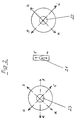
- the left-hand horizontal pair of bracing cylinders can be extended and retracted from the driver's (15) seat in the driver's cab (6) by means of the switching lever (23). This can be seen in particular from the left-hand portion of Figure 2.
- the central switching lever (21) is associated with all the support cylinders (8) and permits simultaneous retraction of the support cylinders when in switch position m, or simultaneous extension of the diagonal support cylinders when in switch position 1, as shown in the central portion of Figure 2.
- Two hydraulically adjustable, side exterior rear-view mirrors (4) are coupled to the hydraulic central control unit (20) (omitted from the illustration of the hydraulic circuit shown in Figure 3).
- the central control unit When the central control unit is operated for the purpose of lowering the placement supports, the hydraulic control cylinders of these exterior rear-view mirrors are automatically laterally extended, so that the lateral placement support region towards the base of the vehicle can be observed on the left and right simultaneously from the driver's (15) seat in the driver's cab (6).
- Both side exterior rear-view mirrors (4) return to their normal position when the placement supports (25 to 28) are completely raised and laterally retracted, i.e. when the fire-fighting vehicle (7) is in its travelling position.
- the fire-fighting vehicle (7) arrives at a place of deployment where, for example, the turntable ladder (11) including the front operator cage (14) is to be swung up and extended
- the switching levers (21 to 23) are operated by the driver (15) in the desired manner as shown in Figure 2, so that the placement supports (25 to 28) make contact with the ground at the sides.
- the switch of an auxiliary power take-off (3) is actuated beforehand, in order to switch on the hydraulic pump (2).
- the hydraulic pump (2) shown in Figure 3 henceforth supplies hydraulic medium, e.g oil, from the oil reservoir (1) shown in Figure 3 to the hydraulic circuit of the central control unit (20).
- Each horizontal bracing cylinder (9) can be individually extended as far as required.
- the operator can immediately climb into the operator cage (14) or into the turntable ladder seat (12) of the main control platform.
- the three-part hydraulic relay valve (24) is designed in particular for a lower pressure of the order of 30 bar.
- the hydraulic system may be replaced by a pneumatic system, which in particular is coupled to the pneumatic system of the vehicle, in order advantageously to make use of a ready-installed medium and to form a control unit which is even easier and simpler.
- the invention is suitable for fire-fighting vehicles, platforms for lifting operations, mobile cranes, etc.
Landscapes
- Engineering & Computer Science (AREA)
- Mechanical Engineering (AREA)
- Physics & Mathematics (AREA)
- Fluid Mechanics (AREA)
- Multimedia (AREA)
- Ladders (AREA)
- Fire-Extinguishing By Fire Departments, And Fire-Extinguishing Equipment And Control Thereof (AREA)
- Rear-View Mirror Devices That Are Mounted On The Exterior Of The Vehicle (AREA)
- Forklifts And Lifting Vehicles (AREA)
Applications Claiming Priority (2)
| Application Number | Priority Date | Filing Date | Title |
|---|---|---|---|
| DE4223041 | 1992-07-14 | ||
| DE4223041A DE4223041A1 (de) | 1992-07-14 | 1992-07-14 | Zentrale Steuereinrichtung für betätigbare Aufstellstützen eines Brandschutzfahrzeuges mit Drehleiter oder dergleichen |
Publications (2)
| Publication Number | Publication Date |
|---|---|
| EP0579181A1 true EP0579181A1 (fr) | 1994-01-19 |
| EP0579181B1 EP0579181B1 (fr) | 1996-05-22 |
Family
ID=6463119
Family Applications (1)
| Application Number | Title | Priority Date | Filing Date |
|---|---|---|---|
| EP93111222A Expired - Lifetime EP0579181B1 (fr) | 1992-07-14 | 1993-07-13 | Unité de commande centrale pour des supports de positionnement contrÔlables d'un véhicule de lutte contre l'incendie équipé d'une échelle tournante ou analogue |
Country Status (3)
| Country | Link |
|---|---|
| EP (1) | EP0579181B1 (fr) |
| AT (1) | ATE138331T1 (fr) |
| DE (2) | DE4223041A1 (fr) |
Cited By (3)
| Publication number | Priority date | Publication date | Assignee | Title |
|---|---|---|---|---|
| CN102991477A (zh) * | 2012-12-05 | 2013-03-27 | 中联重科股份有限公司 | 工程机械及其支腿装置 |
| EP2789786A1 (fr) * | 2013-04-10 | 2014-10-15 | Iveco Magirus Ag | Dispositif élévateur aérien, en particulier un système d'échelle de plateau tournant |
| CN106422126A (zh) * | 2016-10-12 | 2017-02-22 | 山东创能机械科技有限公司 | 一种小型城市消防越野车 |
Families Citing this family (1)
| Publication number | Priority date | Publication date | Assignee | Title |
|---|---|---|---|---|
| CN114307015B (zh) | 2022-02-22 | 2022-06-07 | 徐工消防安全装备有限公司 | 消防车及其控制方法 |
Citations (5)
| Publication number | Priority date | Publication date | Assignee | Title |
|---|---|---|---|---|
| FR1257774A (fr) * | 1960-02-24 | 1961-04-07 | Grue automobile ou engin analogue | |
| DE1634769A1 (de) * | 1965-10-14 | 1970-09-17 | Demag Baumaschinen Gmbh | Steuereinrichtung fuer Bagger oder Kraene mit mehreren hydraulisch bewegbaren Stuetzfuessen |
| US3937563A (en) * | 1974-03-21 | 1976-02-10 | Frabe Donald A | Remote controlled mirror assembly for vehicle |
| US4124226A (en) * | 1977-10-06 | 1978-11-07 | Harnischfeger Corporation | Electrohydraulic outrigger control system |
| EP0163544A2 (fr) * | 1984-05-31 | 1985-12-04 | Salop Tool & Fixtures Limited | Système de stabilisation et nivellage pour caravane ou remorque |
-
1992
- 1992-07-14 DE DE4223041A patent/DE4223041A1/de not_active Withdrawn
-
1993
- 1993-07-13 AT AT93111222T patent/ATE138331T1/de not_active IP Right Cessation
- 1993-07-13 DE DE69302766T patent/DE69302766T2/de not_active Expired - Fee Related
- 1993-07-13 EP EP93111222A patent/EP0579181B1/fr not_active Expired - Lifetime
Patent Citations (5)
| Publication number | Priority date | Publication date | Assignee | Title |
|---|---|---|---|---|
| FR1257774A (fr) * | 1960-02-24 | 1961-04-07 | Grue automobile ou engin analogue | |
| DE1634769A1 (de) * | 1965-10-14 | 1970-09-17 | Demag Baumaschinen Gmbh | Steuereinrichtung fuer Bagger oder Kraene mit mehreren hydraulisch bewegbaren Stuetzfuessen |
| US3937563A (en) * | 1974-03-21 | 1976-02-10 | Frabe Donald A | Remote controlled mirror assembly for vehicle |
| US4124226A (en) * | 1977-10-06 | 1978-11-07 | Harnischfeger Corporation | Electrohydraulic outrigger control system |
| EP0163544A2 (fr) * | 1984-05-31 | 1985-12-04 | Salop Tool & Fixtures Limited | Système de stabilisation et nivellage pour caravane ou remorque |
Cited By (7)
| Publication number | Priority date | Publication date | Assignee | Title |
|---|---|---|---|---|
| CN102991477A (zh) * | 2012-12-05 | 2013-03-27 | 中联重科股份有限公司 | 工程机械及其支腿装置 |
| CN102991477B (zh) * | 2012-12-05 | 2015-08-12 | 中联重科股份有限公司 | 工程机械及其支腿装置 |
| EP2789786A1 (fr) * | 2013-04-10 | 2014-10-15 | Iveco Magirus Ag | Dispositif élévateur aérien, en particulier un système d'échelle de plateau tournant |
| JP2014204979A (ja) * | 2013-04-10 | 2014-10-30 | イフェコ マギルス アーゲー | 架空システム、とりわけ回転はしごシステム |
| US9523237B2 (en) | 2013-04-10 | 2016-12-20 | Iveco Magirus Ag | Aerial system, in particular turntable ladder system |
| RU2645052C2 (ru) * | 2013-04-10 | 2018-02-15 | Ивеко Магирус Аг | Выдвижная многосекционная система, в частности поворотная лесничная система |
| CN106422126A (zh) * | 2016-10-12 | 2017-02-22 | 山东创能机械科技有限公司 | 一种小型城市消防越野车 |
Also Published As
| Publication number | Publication date |
|---|---|
| DE69302766T2 (de) | 1996-10-31 |
| DE4223041A1 (de) | 1994-01-20 |
| DE69302766D1 (de) | 1996-06-27 |
| EP0579181B1 (fr) | 1996-05-22 |
| ATE138331T1 (de) | 1996-06-15 |
Similar Documents
| Publication | Publication Date | Title |
|---|---|---|
| US3858688A (en) | Self-contained mobile extendable tower | |
| US4666183A (en) | Roll-over protection device | |
| CA1098454A (fr) | Appareil de levage a fleche telescopique avec limitation automatique d'extension | |
| US5525019A (en) | Rear platform lift | |
| US5573080A (en) | Work car | |
| US4053061A (en) | Mobile crane | |
| AU743652B2 (en) | System for frame leveling and stabilizing a forklift | |
| EP0579181A1 (fr) | Unité de commande centrale pour des supports de positionnement contrôlables d'un véhicule de lutte contre l'incendie équipé d'une échelle tournante ou analogue | |
| AU4808100A (en) | Hydraulic circuit for isolating a lifting cylinder from a rollstop cylinder in a wheelchair lift | |
| US4381899A (en) | Wheelchair lift device | |
| US5822960A (en) | Reel mower | |
| EP0290892B1 (fr) | Passerelle de commande ajustable pour un véhicule de chargement pour avions | |
| SK279723B6 (sk) | Vozidlo na odvoz odpadkov | |
| JPH0416755Y2 (fr) | ||
| JPH0988126A (ja) | 掘削作業機 | |
| JP3613315B2 (ja) | ブーム制御装置及びブーム式作業車 | |
| EP2308794B1 (fr) | Chariot de manutention commandé par timon, en particulier chariot élévateur | |
| JP2007002430A (ja) | 作業機械における運転室 | |
| JPS5953239A (ja) | 荷役装置の制御装置 | |
| EP0486488B1 (fr) | Elevateur | |
| JP4854218B2 (ja) | 高所作業車 | |
| JP3235819B2 (ja) | 昇降式運転室を有する作業機 | |
| JPH0533517Y2 (fr) | ||
| JP3450532B2 (ja) | 油圧走行農作業機の機体バランス保持構造 | |
| JPS649483B2 (fr) |
Legal Events
| Date | Code | Title | Description |
|---|---|---|---|
| PUAI | Public reference made under article 153(3) epc to a published international application that has entered the european phase |
Free format text: ORIGINAL CODE: 0009012 |
|
| AK | Designated contracting states |
Kind code of ref document: A1 Designated state(s): AT BE CH DE FR GB IT LI NL |
|
| 17P | Request for examination filed |
Effective date: 19940708 |
|
| 17Q | First examination report despatched |
Effective date: 19950505 |
|
| GRAH | Despatch of communication of intention to grant a patent |
Free format text: ORIGINAL CODE: EPIDOS IGRA |
|
| GRAA | (expected) grant |
Free format text: ORIGINAL CODE: 0009210 |
|
| AK | Designated contracting states |
Kind code of ref document: B1 Designated state(s): AT BE CH DE FR GB IT LI NL |
|
| REF | Corresponds to: |
Ref document number: 138331 Country of ref document: AT Date of ref document: 19960615 Kind code of ref document: T |
|
| ITF | It: translation for a ep patent filed | ||
| REF | Corresponds to: |
Ref document number: 69302766 Country of ref document: DE Date of ref document: 19960627 |
|
| ET | Fr: translation filed | ||
| PLBE | No opposition filed within time limit |
Free format text: ORIGINAL CODE: 0009261 |
|
| STAA | Information on the status of an ep patent application or granted ep patent |
Free format text: STATUS: NO OPPOSITION FILED WITHIN TIME LIMIT |
|
| 26N | No opposition filed | ||
| PGFP | Annual fee paid to national office [announced via postgrant information from national office to epo] |
Ref country code: CH Payment date: 19990608 Year of fee payment: 7 |
|
| PGFP | Annual fee paid to national office [announced via postgrant information from national office to epo] |
Ref country code: GB Payment date: 19990609 Year of fee payment: 7 |
|
| PGFP | Annual fee paid to national office [announced via postgrant information from national office to epo] |
Ref country code: AT Payment date: 19990615 Year of fee payment: 7 |
|
| PGFP | Annual fee paid to national office [announced via postgrant information from national office to epo] |
Ref country code: BE Payment date: 19990623 Year of fee payment: 7 |
|
| PGFP | Annual fee paid to national office [announced via postgrant information from national office to epo] |
Ref country code: DE Payment date: 19990728 Year of fee payment: 7 |
|
| PGFP | Annual fee paid to national office [announced via postgrant information from national office to epo] |
Ref country code: NL Payment date: 19990730 Year of fee payment: 7 Ref country code: FR Payment date: 19990730 Year of fee payment: 7 |
|
| PG25 | Lapsed in a contracting state [announced via postgrant information from national office to epo] |
Ref country code: GB Free format text: LAPSE BECAUSE OF NON-PAYMENT OF DUE FEES Effective date: 20000713 Ref country code: AT Free format text: LAPSE BECAUSE OF NON-PAYMENT OF DUE FEES Effective date: 20000713 |
|
| PG25 | Lapsed in a contracting state [announced via postgrant information from national office to epo] |
Ref country code: LI Free format text: LAPSE BECAUSE OF NON-PAYMENT OF DUE FEES Effective date: 20000731 Ref country code: CH Free format text: LAPSE BECAUSE OF NON-PAYMENT OF DUE FEES Effective date: 20000731 Ref country code: BE Free format text: LAPSE BECAUSE OF NON-PAYMENT OF DUE FEES Effective date: 20000731 |
|
| BERE | Be: lapsed |
Owner name: IVECO MAGIRUS A.G. Effective date: 20000731 |
|
| PG25 | Lapsed in a contracting state [announced via postgrant information from national office to epo] |
Ref country code: NL Free format text: LAPSE BECAUSE OF NON-PAYMENT OF DUE FEES Effective date: 20010201 |
|
| GBPC | Gb: european patent ceased through non-payment of renewal fee |
Effective date: 20000713 |
|
| REG | Reference to a national code |
Ref country code: CH Ref legal event code: PL |
|
| PG25 | Lapsed in a contracting state [announced via postgrant information from national office to epo] |
Ref country code: FR Free format text: LAPSE BECAUSE OF NON-PAYMENT OF DUE FEES Effective date: 20010330 |
|
| NLV4 | Nl: lapsed or anulled due to non-payment of the annual fee |
Effective date: 20010201 |
|
| REG | Reference to a national code |
Ref country code: FR Ref legal event code: ST |
|
| PG25 | Lapsed in a contracting state [announced via postgrant information from national office to epo] |
Ref country code: DE Free format text: LAPSE BECAUSE OF NON-PAYMENT OF DUE FEES Effective date: 20010501 |
|
| PG25 | Lapsed in a contracting state [announced via postgrant information from national office to epo] |
Ref country code: IT Free format text: LAPSE BECAUSE OF NON-PAYMENT OF DUE FEES;WARNING: LAPSES OF ITALIAN PATENTS WITH EFFECTIVE DATE BEFORE 2007 MAY HAVE OCCURRED AT ANY TIME BEFORE 2007. THE CORRECT EFFECTIVE DATE MAY BE DIFFERENT FROM THE ONE RECORDED. Effective date: 20050713 |