EP0579251B1 - Gas-Flüssigkeits-Mischer für veränderliche Flüssigkeitshöhen - Google Patents
Gas-Flüssigkeits-Mischer für veränderliche Flüssigkeitshöhen Download PDFInfo
- Publication number
- EP0579251B1 EP0579251B1 EP93111464A EP93111464A EP0579251B1 EP 0579251 B1 EP0579251 B1 EP 0579251B1 EP 93111464 A EP93111464 A EP 93111464A EP 93111464 A EP93111464 A EP 93111464A EP 0579251 B1 EP0579251 B1 EP 0579251B1
- Authority
- EP
- European Patent Office
- Prior art keywords
- draft tube
- hollow
- liquid
- gas
- eductor
- Prior art date
- Legal status (The legal status is an assumption and is not a legal conclusion. Google has not performed a legal analysis and makes no representation as to the accuracy of the status listed.)
- Expired - Lifetime
Links
- 239000007788 liquid Substances 0.000 title claims description 96
- 230000037406 food intake Effects 0.000 claims description 9
- 238000005086 pumping Methods 0.000 claims description 8
- 238000004891 communication Methods 0.000 claims description 6
- 239000012530 fluid Substances 0.000 claims description 5
- 238000011161 development Methods 0.000 claims description 4
- 239000000203 mixture Substances 0.000 claims description 4
- XLYOFNOQVPJJNP-UHFFFAOYSA-N water Substances O XLYOFNOQVPJJNP-UHFFFAOYSA-N 0.000 claims description 2
- 239000007789 gas Substances 0.000 description 40
- 238000006243 chemical reaction Methods 0.000 description 27
- 239000000463 material Substances 0.000 description 4
- 239000007787 solid Substances 0.000 description 4
- 238000005984 hydrogenation reaction Methods 0.000 description 3
- 238000012545 processing Methods 0.000 description 3
- IJGRMHOSHXDMSA-UHFFFAOYSA-N Atomic nitrogen Chemical compound N#N IJGRMHOSHXDMSA-UHFFFAOYSA-N 0.000 description 2
- 230000015572 biosynthetic process Effects 0.000 description 2
- 238000005516 engineering process Methods 0.000 description 2
- 238000000034 method Methods 0.000 description 2
- LQNUZADURLCDLV-UHFFFAOYSA-N nitrobenzene Chemical compound [O-][N+](=O)C1=CC=CC=C1 LQNUZADURLCDLV-UHFFFAOYSA-N 0.000 description 2
- 238000006213 oxygenation reaction Methods 0.000 description 2
- 230000008569 process Effects 0.000 description 2
- 230000003134 recirculating effect Effects 0.000 description 2
- ZAMOUSCENKQFHK-UHFFFAOYSA-N Chlorine atom Chemical compound [Cl] ZAMOUSCENKQFHK-UHFFFAOYSA-N 0.000 description 1
- 229910000831 Steel Inorganic materials 0.000 description 1
- RTAQQCXQSZGOHL-UHFFFAOYSA-N Titanium Chemical compound [Ti] RTAQQCXQSZGOHL-UHFFFAOYSA-N 0.000 description 1
- 230000009471 action Effects 0.000 description 1
- QVGXLLKOCUKJST-UHFFFAOYSA-N atomic oxygen Chemical compound [O] QVGXLLKOCUKJST-UHFFFAOYSA-N 0.000 description 1
- 230000008901 benefit Effects 0.000 description 1
- 239000006227 byproduct Substances 0.000 description 1
- 238000005660 chlorination reaction Methods 0.000 description 1
- 239000000460 chlorine Substances 0.000 description 1
- 229910052801 chlorine Inorganic materials 0.000 description 1
- -1 e.g. Substances 0.000 description 1
- 238000005188 flotation Methods 0.000 description 1
- 239000011521 glass Substances 0.000 description 1
- 239000001257 hydrogen Substances 0.000 description 1
- 229910052739 hydrogen Inorganic materials 0.000 description 1
- 125000004435 hydrogen atom Chemical class [H]* 0.000 description 1
- 230000001771 impaired effect Effects 0.000 description 1
- 238000010348 incorporation Methods 0.000 description 1
- 229910001092 metal group alloy Inorganic materials 0.000 description 1
- 238000012986 modification Methods 0.000 description 1
- 230000004048 modification Effects 0.000 description 1
- 229910052757 nitrogen Inorganic materials 0.000 description 1
- 239000001301 oxygen Substances 0.000 description 1
- 229910052760 oxygen Inorganic materials 0.000 description 1
- 239000004033 plastic Substances 0.000 description 1
- 229920003023 plastic Polymers 0.000 description 1
- 239000000376 reactant Substances 0.000 description 1
- 239000010935 stainless steel Substances 0.000 description 1
- 229910001220 stainless steel Inorganic materials 0.000 description 1
- 239000010959 steel Substances 0.000 description 1
- 239000000126 substance Substances 0.000 description 1
- 239000010936 titanium Substances 0.000 description 1
- 229910052719 titanium Inorganic materials 0.000 description 1
Images
Classifications
-
- B—PERFORMING OPERATIONS; TRANSPORTING
- B01—PHYSICAL OR CHEMICAL PROCESSES OR APPARATUS IN GENERAL
- B01J—CHEMICAL OR PHYSICAL PROCESSES, e.g. CATALYSIS OR COLLOID CHEMISTRY; THEIR RELEVANT APPARATUS
- B01J19/00—Chemical, physical or physico-chemical processes in general; Their relevant apparatus
- B01J19/18—Stationary reactors having moving elements inside
- B01J19/1868—Stationary reactors having moving elements inside resulting in a loop-type movement
- B01J19/1875—Stationary reactors having moving elements inside resulting in a loop-type movement internally, i.e. the mixture circulating inside the vessel such that the upwards stream is separated physically from the downwards stream(s)
-
- B—PERFORMING OPERATIONS; TRANSPORTING
- B01—PHYSICAL OR CHEMICAL PROCESSES OR APPARATUS IN GENERAL
- B01F—MIXING, e.g. DISSOLVING, EMULSIFYING OR DISPERSING
- B01F23/00—Mixing according to the phases to be mixed, e.g. dispersing or emulsifying
- B01F23/20—Mixing gases with liquids
- B01F23/23—Mixing gases with liquids by introducing gases into liquid media, e.g. for producing aerated liquids
- B01F23/233—Mixing gases with liquids by introducing gases into liquid media, e.g. for producing aerated liquids using driven stirrers with completely immersed stirring elements
- B01F23/2331—Mixing gases with liquids by introducing gases into liquid media, e.g. for producing aerated liquids using driven stirrers with completely immersed stirring elements characterised by the introduction of the gas along the axis of the stirrer or along the stirrer elements
- B01F23/23314—Mixing gases with liquids by introducing gases into liquid media, e.g. for producing aerated liquids using driven stirrers with completely immersed stirring elements characterised by the introduction of the gas along the axis of the stirrer or along the stirrer elements through a hollow stirrer element
-
- B—PERFORMING OPERATIONS; TRANSPORTING
- B01—PHYSICAL OR CHEMICAL PROCESSES OR APPARATUS IN GENERAL
- B01F—MIXING, e.g. DISSOLVING, EMULSIFYING OR DISPERSING
- B01F23/00—Mixing according to the phases to be mixed, e.g. dispersing or emulsifying
- B01F23/20—Mixing gases with liquids
- B01F23/23—Mixing gases with liquids by introducing gases into liquid media, e.g. for producing aerated liquids
- B01F23/233—Mixing gases with liquids by introducing gases into liquid media, e.g. for producing aerated liquids using driven stirrers with completely immersed stirring elements
- B01F23/2334—Mixing gases with liquids by introducing gases into liquid media, e.g. for producing aerated liquids using driven stirrers with completely immersed stirring elements provided with stationary guiding means surrounding at least partially the stirrer
- B01F23/23341—Mixing gases with liquids by introducing gases into liquid media, e.g. for producing aerated liquids using driven stirrers with completely immersed stirring elements provided with stationary guiding means surrounding at least partially the stirrer with tubes surrounding the stirrer
-
- B—PERFORMING OPERATIONS; TRANSPORTING
- B01—PHYSICAL OR CHEMICAL PROCESSES OR APPARATUS IN GENERAL
- B01F—MIXING, e.g. DISSOLVING, EMULSIFYING OR DISPERSING
- B01F23/00—Mixing according to the phases to be mixed, e.g. dispersing or emulsifying
- B01F23/20—Mixing gases with liquids
- B01F23/23—Mixing gases with liquids by introducing gases into liquid media, e.g. for producing aerated liquids
- B01F23/233—Mixing gases with liquids by introducing gases into liquid media, e.g. for producing aerated liquids using driven stirrers with completely immersed stirring elements
- B01F23/2335—Mixing gases with liquids by introducing gases into liquid media, e.g. for producing aerated liquids using driven stirrers with completely immersed stirring elements characterised by the direction of introduction of the gas relative to the stirrer
- B01F23/23353—Mixing gases with liquids by introducing gases into liquid media, e.g. for producing aerated liquids using driven stirrers with completely immersed stirring elements characterised by the direction of introduction of the gas relative to the stirrer the gas being sucked towards the rotating stirrer
-
- B—PERFORMING OPERATIONS; TRANSPORTING
- B01—PHYSICAL OR CHEMICAL PROCESSES OR APPARATUS IN GENERAL
- B01F—MIXING, e.g. DISSOLVING, EMULSIFYING OR DISPERSING
- B01F23/00—Mixing according to the phases to be mixed, e.g. dispersing or emulsifying
- B01F23/20—Mixing gases with liquids
- B01F23/23—Mixing gases with liquids by introducing gases into liquid media, e.g. for producing aerated liquids
- B01F23/2366—Parts; Accessories
- B01F23/2368—Mixing receptacles, e.g. tanks, vessels or reactors, being completely closed, e.g. hermetically closed
-
- B—PERFORMING OPERATIONS; TRANSPORTING
- B01—PHYSICAL OR CHEMICAL PROCESSES OR APPARATUS IN GENERAL
- B01J—CHEMICAL OR PHYSICAL PROCESSES, e.g. CATALYSIS OR COLLOID CHEMISTRY; THEIR RELEVANT APPARATUS
- B01J19/00—Chemical, physical or physico-chemical processes in general; Their relevant apparatus
- B01J19/18—Stationary reactors having moving elements inside
- B01J19/20—Stationary reactors having moving elements inside in the form of helices, e.g. screw reactors
-
- B—PERFORMING OPERATIONS; TRANSPORTING
- B01—PHYSICAL OR CHEMICAL PROCESSES OR APPARATUS IN GENERAL
- B01F—MIXING, e.g. DISSOLVING, EMULSIFYING OR DISPERSING
- B01F2215/00—Auxiliary or complementary information in relation with mixing
- B01F2215/04—Technical information in relation with mixing
- B01F2215/0413—Numerical information
- B01F2215/0418—Geometrical information
- B01F2215/0422—Numerical values of angles
-
- B—PERFORMING OPERATIONS; TRANSPORTING
- B01—PHYSICAL OR CHEMICAL PROCESSES OR APPARATUS IN GENERAL
- B01F—MIXING, e.g. DISSOLVING, EMULSIFYING OR DISPERSING
- B01F2215/00—Auxiliary or complementary information in relation with mixing
- B01F2215/04—Technical information in relation with mixing
- B01F2215/0413—Numerical information
- B01F2215/0436—Operational information
- B01F2215/0481—Numerical speed values
-
- B—PERFORMING OPERATIONS; TRANSPORTING
- B01—PHYSICAL OR CHEMICAL PROCESSES OR APPARATUS IN GENERAL
- B01F—MIXING, e.g. DISSOLVING, EMULSIFYING OR DISPERSING
- B01F23/00—Mixing according to the phases to be mixed, e.g. dispersing or emulsifying
- B01F23/20—Mixing gases with liquids
- B01F23/23—Mixing gases with liquids by introducing gases into liquid media, e.g. for producing aerated liquids
- B01F23/233—Mixing gases with liquids by introducing gases into liquid media, e.g. for producing aerated liquids using driven stirrers with completely immersed stirring elements
- B01F23/2331—Mixing gases with liquids by introducing gases into liquid media, e.g. for producing aerated liquids using driven stirrers with completely immersed stirring elements characterised by the introduction of the gas along the axis of the stirrer or along the stirrer elements
- B01F23/23311—Mixing gases with liquids by introducing gases into liquid media, e.g. for producing aerated liquids using driven stirrers with completely immersed stirring elements characterised by the introduction of the gas along the axis of the stirrer or along the stirrer elements through a hollow stirrer axis
-
- B—PERFORMING OPERATIONS; TRANSPORTING
- B01—PHYSICAL OR CHEMICAL PROCESSES OR APPARATUS IN GENERAL
- B01F—MIXING, e.g. DISSOLVING, EMULSIFYING OR DISPERSING
- B01F23/00—Mixing according to the phases to be mixed, e.g. dispersing or emulsifying
- B01F23/20—Mixing gases with liquids
- B01F23/23—Mixing gases with liquids by introducing gases into liquid media, e.g. for producing aerated liquids
- B01F23/233—Mixing gases with liquids by introducing gases into liquid media, e.g. for producing aerated liquids using driven stirrers with completely immersed stirring elements
- B01F23/2336—Mixing gases with liquids by introducing gases into liquid media, e.g. for producing aerated liquids using driven stirrers with completely immersed stirring elements characterised by the location of the place of introduction of the gas relative to the stirrer
- B01F23/23363—Mixing gases with liquids by introducing gases into liquid media, e.g. for producing aerated liquids using driven stirrers with completely immersed stirring elements characterised by the location of the place of introduction of the gas relative to the stirrer the gas being introduced above the stirrer
-
- B—PERFORMING OPERATIONS; TRANSPORTING
- B01—PHYSICAL OR CHEMICAL PROCESSES OR APPARATUS IN GENERAL
- B01F—MIXING, e.g. DISSOLVING, EMULSIFYING OR DISPERSING
- B01F27/00—Mixers with rotary stirring devices in fixed receptacles; Kneaders
- B01F27/05—Stirrers
- B01F27/11—Stirrers characterised by the configuration of the stirrers
- B01F27/112—Stirrers characterised by the configuration of the stirrers with arms, paddles, vanes or blades
- B01F27/1121—Stirrers characterised by the configuration of the stirrers with arms, paddles, vanes or blades pin-shaped
-
- B—PERFORMING OPERATIONS; TRANSPORTING
- B01—PHYSICAL OR CHEMICAL PROCESSES OR APPARATUS IN GENERAL
- B01F—MIXING, e.g. DISSOLVING, EMULSIFYING OR DISPERSING
- B01F27/00—Mixers with rotary stirring devices in fixed receptacles; Kneaders
- B01F27/05—Stirrers
- B01F27/11—Stirrers characterised by the configuration of the stirrers
- B01F27/114—Helically shaped stirrers, i.e. stirrers comprising a helically shaped band or helically shaped band sections
- B01F27/1144—Helically shaped stirrers, i.e. stirrers comprising a helically shaped band or helically shaped band sections with a plurality of blades following a helical path on a shaft or a blade support
-
- B—PERFORMING OPERATIONS; TRANSPORTING
- B01—PHYSICAL OR CHEMICAL PROCESSES OR APPARATUS IN GENERAL
- B01F—MIXING, e.g. DISSOLVING, EMULSIFYING OR DISPERSING
- B01F27/00—Mixers with rotary stirring devices in fixed receptacles; Kneaders
- B01F27/05—Stirrers
- B01F27/11—Stirrers characterised by the configuration of the stirrers
- B01F27/19—Stirrers with two or more mixing elements mounted in sequence on the same axis
- B01F27/192—Stirrers with two or more mixing elements mounted in sequence on the same axis with dissimilar elements
Definitions
- the invention relates to gas-liquid mixing operations. More particularly, it relates to enhanced gas-liquid mixing under particular variable liquid level operating conditions.
- the Advanced Gas Reactor (AGR) system employs a down-pumping impeller positioned within a hollow draft tube in a mixing vessel to create a recirculating flow pattern in a body of liquid contained in the vessel. Because of such recirculation of the liquid downward in the hollow draft tube and upward in the vessel outside said draft tube, vortices are formed in the upper inlet area of the draft tube so as to draw feed gas from an overhead gas space within the vessel into the recirculating liquid passing downward into the draft tube, as disclosed in the Litz patent, U.S. Re. 32,562.
- the apparatus of the subject invention is defined in claim 1.
- this apparatus the location and geometry of hollow gas ingestion tubes are matched with the gas requirements of the helical impeller of an AGR system to maximize gas-liquid mixing and reaction rates.
- all of the gas is desirably ingested into the draft tube where the reaction rate is highest.
- the objects of the invention are accomplished by employing hollow gas ingestion tubes, i.e., eductors, desirably positioned and with a geometry such as to enable an impeller/draft tube system to efficiently provide desired gas/liquid mixing in a reactor vessel subject to large variations in liquid level during the mixing operation. Liquid level variations of as much as 2.4 m (8 feet) or more can be tolerated in the practice of the invention.
- hollow gas ingestion tubes i.e., eductors
- a downward pumping helical impeller is positioned in a hollow draft tube having open ends at the top and bottom thereof as in conventional AGR systems.
- the draft tube is positioned in the lower half, preferably in the lower third of the reaction vessel.
- the bottom of the draft tube is located no closer than three quarters (3/4) of a draft tube diameter in length above the bottom of the reaction vessel, and preferably one diameter in length above the bottom of the reactor vessel.
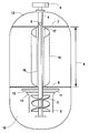
- reaction vessel 1 has draft tube 2 thus positioned in the lower portion thereof. Impeller means 3 is positioned in such draft tube 2 and is driven by drive shaft 4 extending upward through reaction vessel 1 to drive motor 5 positioned above said reaction vessel.
- drive shaft 4 is a hollow shaft having gas inlet means 6 in the upper portion thereof above the maximum liquid level 7 to be encountered in the course of gas-liquid operations in the reaction vessel.
- the lower liquid level within said reaction vessel 1 is indicated by the numeral 8, with the difference between lower liquid level 8 and maximum liquid level 7 representing the liquid level variation 9 encountered in the course of gas-liquid operations using the mixing system of the invention.
- two eductor tubes 10 and 11 are affixed to hollow drive shaft 4 and are in fluid communication with the inner portion thereof.
- said eductor tubes are hollow tubes that extend radially outward from hollow drive shaft 4 into the body of liquid 12 in reaction vessel 1, gas communication is established from overhead gas space 13 in reaction vessel 1, through said hollow drive shaft 4 and eductor tubes 10 and 11, to said body of liquid 12.
- gas is drawn from the overhead gas to the eductor tubes and is discharged therefrom into the body of liquid in the region above draft tube 2.
- Eductor tubes 10 and 11 are spaced 180° apart and are located at a distance of 1/4 to 1 1/2 times the diameter of the draft tube above the top of the draft tube. Preferably, the eductors are located from 1/2 to 1 diameter above the top of the draft tube. It will be noted from Fig. 1 that the impeller-draft-tube assembly located in the bottom portion of reaction vessel 1, as indicated above, is totally submerged below lower liquid level 8. Likewise, eductor tubes 10 and 11 are so positioned below said lower liquid level 8.
- the eductor tubes extend outwardly to a end-to-end length, i.e., from the outer end of eductor tube 10 on one side of hollow drive shaft 4 to the outer end of eductor tube 11 on the outer side of said drive shaft, of from 1/2 to 1 1/2 times the diameter of draft tube 2, preferably 1 to 1 1/4 times said diameter of the draft tube.
- draft tube 2 is illustrated in the drawing as having an outwardly extending conical section 14 at the top thereof to facilitate the flow of gas bubbles and liquid into the draft tube.
- the diameter of the draft tube as referred to above, generally refers to the diameter of the main body of draft tube 2 rather than to the outer diameter of the optional conical section.
- the total end-to-end eductor length is generally desirable for the total end-to-end eductor length to be equal to the large outer diameter of the conical section.
- the eductor tubes are typically fabricated from standard sizes of extra heavy wall pipe, with the outside diameter of said eductors being generally between about 1/17 and 1/19 the diameter of the draft tube although other sizes can also be employed in the practice of the invention.
- split draft tube 15 has two axial, upwardly extending openings or splits 16 and 17 on opposite sides of the draft tube. It is within the scope of the invention to provide any convenient number of such axial, upwardly extending splits, or to provide other forms of openings so as to enable upwardly flowing liquid to pass into the interior of said split draft tube for recirculation downwardly therein, facilitating the circulation of liquid throughout the reaction vessel.
- reaction vessel 1 liquid flowing upward in reaction vessel 1 outside draft tube 2 and past eductor tubes 10 and 11 will tend, in the course of its further upward movement, to pass through splits 16 and 17 of split draft tube 15 for recirculation downward to the vicinity of draft tube 2, from which it is drawn through said draft tube 2 under the influence of impeller means 3.
- the height of reaction vessel 1 is not particularly large as compared to the diameter thereof, those skilled in the art will appreciate that there is little or no advantage to incorporating an optional split draft tube in the system of the invention.
- the eductor tubes In the practice of the invention, it is generally desirable to rotate the eductor tubes so as to achieve a tip speed at the ends thereof of between 457 and 914 m/min (1,500 and 3,000 FPM).
- said top speed is preferably from about 610 to about 732 m/min (2,000 to about 2,400 FPM).
- eductor tubes can be applied to hollow drive shaft 4 at the predetermined location above the draft tube.
- Such eductor tubes are generally spaced at equal angles around the draft tube, so that three such inductor tubes would generally be spaced 120° apart, while four such eductor tubes would generally be spaced 90° apart.
- the invention enables essentially all of the gas to be ingested into the draft tube, where the highest reaction rate occurs.
- a sparger ring will typically be provided below the draft tube for gas introduction purposes.
- the sparger ring will typically have a diameter the same as that of the draft tube, with appropriate holes pointing downward for said gas introduction purposes.
- Such angle of art which serves to facilitate the flow of gas from the eductor tubes into the body of liquid in the reaction vessel, is generally from 30° to 90°, preferably about 45°.
- the invention has been described particularly with reference to conventional gas-liquid mixing operations, e.g., hydrogenation of organic liquids or the oxygenation or chlorination thereof, in which variable liquid levels may cause non-optimum operation of an AGR system.
- gas-liquid mixing operations e.g., hydrogenation of organic liquids or the oxygenation or chlorination thereof, in which variable liquid levels may cause non-optimum operation of an AGR system.
- the hydrogenation of nitrobenzene to form analine, with by-product water is a typical example of such circumstance.
- an inert or expensive gas e.g., nitrogen
- it is advantageous to be able to recirculate gas from the head space, as provided herein, for mixing with a body of solids-containing liquid, when coupled with an efficient liquid pumping system.
- any suitable axial flow down-pumping impeller means can be employed to create the desired downward flow of liquid in the draft tube with resulting vortex formation to draw a gas bubble-liquid mixture into the draft tube for enhanced mixing therein. While helical impellers, typically with a single or double helix configuration, are generally preferred, marine impellers or other commercially available axial flow impellers can also be employed.
- Various baffle means can also be included in the reaction vessel to facilitate the desired circulation of liquid upward in the annular space between the impeller-containing draft tube and the walls of the reaction vessel and into the upper split draft tube if such is employed in particular embodiments of the invention.
- the components of the system can be made of any conventional, conveniently available materials compatible with the contemplated gas-liquid mixing operation to be carried out therein.
- various metal alloys, plastics and glass materials may be employed in particular applications.
- suitable materials include stainless steel, rubber coated steel, titanium and the like.
- the invention will be seen from the description above to enable AGR processing operations to be desirably carried out in applications in which non-optimum, variable liquid levels in the reaction vessel inhibit proper vortex development and desired gas ingestion from the overhead gas space into the liquid in the reaction vessel.
- the invention which is particularly desirable where it is desirable to recirculate valuable head space gas back into the liquid, extends the range of application to which the highly desirable AGR technology is applicable.
- the invention thus enhances the use of AGR technology to desirable processing operations in which hydrogen, oxygen, chlorine or other industrial gases are to be mixed with liquids over a broad range of liquid level conditions within the reaction vessel.
Landscapes
- Chemical & Material Sciences (AREA)
- Chemical Kinetics & Catalysis (AREA)
- Organic Chemistry (AREA)
- Mixers Of The Rotary Stirring Type (AREA)
- Physical Or Chemical Processes And Apparatus (AREA)
- Aeration Devices For Treatment Of Activated Polluted Sludge (AREA)
Claims (22)
- Vorrichtung zum Mischen eines Gases und einer Flüssigkeit in einem Mischgefäß, wobei sich die Tiefe eines Körpers der Flüssigkeit im Verlauf des Mischvorgangs ändert, mit:(a) einem Mischgefäß (1) zum Mischen eines Gases und einer Flüssigkeit;(b) einer innerhalb des Mischgefäßes (1) in dessen unterer Hälfte angeordneten Laufrad/Leitrohr-Anordnung, wobei der untere Rand des Leitrohrs nicht näher als ³/₄ des Durchmessers des Leitrohrs über dem Boden des Mischgefäßes liegt und wobei die Laufrad/Leitrohr-Anordnung ein hohles Leitrohr (2) mit einer abwärts pumpenden Axialstrom-Laufradanordnung (3) aufweist, welche in diesem angeordnet ist, um eine Wirbelströmung auszubilden und ein Gasblasen/Flüssigkeits-Gemisch aufzunehmen, so daß dieses nach unten durch das Leitrohr strömt, wobei die besagte Anordnung unterhalb des niedrigsten, während des Gas/Flüssigkeits-Mischvorgangs auftretenden Flüssigkeitspegels (8) angeordnet ist;(c) einer nach oben durch das Mischgefäß (1) verlaufenden Antriebswellenanordnung (4) zum Drehen der Laufradanordnung (3) der besagten Laufrad/Leitrohr-Anordnung, um eine Zirkulation des Gasblasen/Flüssigkeits-Gemisches nach unten durch das hohle Leitrohr (2) zu bewirken, wobei das Gasblasen/Flüssigkeits-Gemisch von dem unteren Ende des Leitrohrs austritt, um nach oben in den ringförmigen Raum zwischen dem Leitrohr und der Wand des Mischgefäßes zu strömen;(d) mindestens zwei hohlen Eduktorrohren (10, 11), die oberhalb der Laufrad/Leitrohr-Anordnung von der Antriebswellenanordnung (4) radial nach außen in den Flüssigkeitskörper (12) in dem Mischgefäß (1) verlaufen, wobei die hohlen Eduktorrohre in Abstand zueinander angeordnet sind und in einem Abstand des ¹/₄- bis 1¹/₂-fachen Durchmessers des Leitrohrs (2) oberhalb des oberen Randes des Leitrohrs verlaufen, wobei die hohlen Eduktorrohre eine von einem Ende zum anderen Ende gemessene Gesamtlänge von dem äußeren Ende des einen hohlen Eduktorrohrs bis zum äußeren Ende des anderen haben, die zwischen dem ¹/₂- bis 1¹/₂-fachen Durchmesser des Leitrohrs liegt; und(e) einer oberhalb des höchsten, während des Gas/Flüssigkeits-Mischvorgangs auftretenden Flüssigkeitspegels (7) angeordneten Leitungsanordnung (4) zur Ausbildung einer Fluidverbindung zwischen den hohlen Eduktorrohren und dem Überkopf-Gasraum (13) über der Oberfläche des Flüssigkeitskörpers (12) in dem Mischgefäß (1),wodurch ein effizientes Gas/Flüssigkeits-Mischen bei Vorgängen mit variablem Flüssigkeits-Arbeitspegel aufrechterhalten wird, wobei eine wünschenswerte Umwälzung voll Gas von dem Überkopf-Gasraum in den Flüssigkeitskörper stattfindet.
- Vorrichtung nach Anspruch 1, bei welcher die Laufrad/Leitrohr-Anordnung im unteren Drittel des Mischgefäßes angeordnet ist.
- Vorrichtung nach Anspruch 1, bei welcher die hohlen Eduktorrohre (10, 11) in einem Abstand des 1¹/₂- bis 1-fachen Durchmessers des Leitrohrs (2) oberhalb des oberen Rands des Leitrohrs angeordnet sind.
- Vorrichtung nach Anspruch 1, bei welcher die hohlen Eduktorrohre (10, 11) eine von einem Ende zum anderen Ende gemessene Gesamtlänge von dem äußeren Ende des einen hohlen Eduktorrohrs bis zum äußeren Ende des anderen haben, die zwischen dem 1- bis 1¹/₄-fachen Durchmesser des Leitrohrs (2) liegt.
- Vorrichtung nach Anspruch 1, bei welcher die Antriebswellenanordnung eine Antriebswelle (4) aufweist, die einen hohlen Abschnitt beinhaltet, der sich von über dem höchsten, während des Gas/Flüssigkeits-Mischvorgangs auftretenden Flüssigkeitspegels (7) bis zu der Position der hohlen Eduktorrohre (10, 11) erstreckt, wobei der hohle Abschnitt die Leitungsanordnung zum Ausbilden der Fluidverbindung zwischen den hohlen Eduktorrohren und dem Überkopf-Gasraum (13) der Oberfläche des Flüssigkeitskörpers (12) in dem Mischgefäß (1) darstellt und eine Gaseinlaßanordnung (6) in der Antriebswelle aufweist, um Gas von dem Überkopf-Gasraum zu dem hohlen Abschnitt der Antriebswelle strömen zu lassen.
- Vorrichtung nach Anspruch 1, bei welcher die Leitungsanordnung Leitungen aufweist, die an der Antriebswellenanordnung (4) befestigt sind und sich von oberhalb des höchsten, während des Gas/Flüssigkeits-Mischvorgangs auftretenden Flüssigkeitspegels (7) bis zu der Position der hohlen Eduktorrohre (10, 11) erstrecken.
- Vorrichtung nach Anspruch 1, bei welcher zwei hohle Eduktorrohre (10, 11) von der Antriebswellenanordnung (4) radial nach außen verlaufen.
- Vorrichtung nach Anspruch 7, bei welcher die hohlen Eduktorrohre (10, 11) uni 180° versetzt sind.
- Vorrichtung nach Anspruch 1, bei welcher drei hohle Eduktorrohre von der Antriebswellenanordnung radial nach außen verlaufen.
- Vorrichtung nach Anspruch 9, bei welcher die besagten hohlen Eduktorrohre um 120° versetzt sind.
- Vorrichtung nach Anspruch 1, bei welcher vier hohle Eduktorrohre von der Antriebswellenanordnung radial nach außen verlaufen.
- Vorrichtung nach Anspruch 11, bei welcher die besagten hohlen Eduktorrohre um 90° versetzt sind.
- Vorrichtung nach Anspruch 1, bei welcher die Antriebswellenanordnung (4) die hohlen Eduktorrohre (10, 11) mit einer an deren Spitze gemessenen Geschwindigkeit von zwischen 457 bis 914 m/min (1500 bis 3000 FPM) drehen kann.
- Vorrichtung nach Anspruch 13, bei welcher die Antriebswellenanordnung (4) die hohlen Eduktorrohre (10, 11) mit einer an deren Spitze gemessenen Geschwindigkeit von zwischen 610 bis 732 m/min (2000 bis 2400 FPM) drehen kann.
- Vorrichtung nach Anspruch 1, bei welcher die äußeren Enden der hohlen Eduktorrohre unter einem Winkel zu der Richtung des durch diese stattfindenden Gasstromes angeschrägt ist.
- Vorrichtung nach Anspruch 15, bei welcher der Anschrägewinkel zwischen 30° und 90° liegt.
- Vorrichtung nach Anspruch 16, bei welcher der Anschrägewinkel etwa 45° beträgt.
- Vorrichtung nach Anspruch 1 mit einem gespaltenen Leitrohr (15), das oberhalb der Laufrad/Leitrohr-Anordnung in dem Bereich des Flüssigkeitskörpers (12) in dem Mischgefäß (1) angeordnet ist, der zwischen dem niedrigsten und dem höchsten, während des Gas/Flüssigkeits-Mischvorgangs auftretenden Flüssigkeitspegel (8, 7) liegt, wobei das gespaltene Leitrohr mit Öffnungen (16, 17) versehen ist, so daß in dem Mischgefäß nach oben strömende Flüssigkeit in das Innere des gespaltenen Leitrohrs gelangen kann, um in diesem nach unten in die Nähe der Laufrad/Leitrohr-Anordnung umgewälzt zu werden.
- Vorrichtung nach Anspruch 18, bei welcher das gespaltene Leitrohr (15) nach oben verlaufende Axialschlitze (16, 17) aufweist, welche die besagten Öffnungen für den Durchtritt von Flüssigkeit durch diese darstellen.
- Vorrichtung nach Anspruch 19, bei welcher das gespaltene Leitrohr (15) zwei nach oben verlaufende Axialschlitze (16, 17) aufweist, die auf gegenüberliegenden Seiten desselben angeordnet sind.
- Vorrichtung nach Anspruch 18, bei welcher die hohlen Eduktorrohre (10, 11) in einem Abstand des ¹/₂- bis 1-fachen Durchmessers des Leitrohrs (2) über dem oberen Rand des Leitrohrs angeordnet sind, und wobei die Laufrad/Leitrohr-Anordnung im unteren Drittel des Mischgefäßes (1) angeordnet ist.
- Vorrichtung nach Anspruch 1, bei welcher der untere Rand des Leitrohrs (2) etwa einen Durchmesser des Leitrohrs über dem Boden des Mischgefäßes (1) angeordnet ist.
Applications Claiming Priority (2)
| Application Number | Priority Date | Filing Date | Title |
|---|---|---|---|
| US914333 | 1992-07-17 | ||
| US07/914,333 US5244603A (en) | 1992-07-17 | 1992-07-17 | Enhanced gas-liquid mixing under variable liquid operating level conditions |
Publications (2)
| Publication Number | Publication Date |
|---|---|
| EP0579251A1 EP0579251A1 (de) | 1994-01-19 |
| EP0579251B1 true EP0579251B1 (de) | 1996-01-31 |
Family
ID=25434207
Family Applications (1)
| Application Number | Title | Priority Date | Filing Date |
|---|---|---|---|
| EP93111464A Expired - Lifetime EP0579251B1 (de) | 1992-07-17 | 1993-07-16 | Gas-Flüssigkeits-Mischer für veränderliche Flüssigkeitshöhen |
Country Status (7)
| Country | Link |
|---|---|
| US (1) | US5244603A (de) |
| EP (1) | EP0579251B1 (de) |
| JP (1) | JPH06182171A (de) |
| BR (1) | BR9302893A (de) |
| CA (1) | CA2100740C (de) |
| ES (1) | ES2083228T3 (de) |
| MX (1) | MX9304305A (de) |
Families Citing this family (35)
| Publication number | Priority date | Publication date | Assignee | Title |
|---|---|---|---|---|
| US5451348A (en) * | 1994-04-18 | 1995-09-19 | Praxair Technology, Inc. | Variable liquid level eductor/impeller gas-liquid mixing apparatus and process |
| DE69522365T2 (de) * | 1994-05-11 | 2002-05-23 | Praxair Technology Inc | Verbesserungen bei der Oxidation organischer Chemikalien |
| US5558842A (en) * | 1995-06-07 | 1996-09-24 | Twenty-First Century Research Corporation | Devices for making reaction products by controlling pre-coalescing temperature and transient temperature difference in an atomized liquid |
| US5883292A (en) * | 1996-01-17 | 1999-03-16 | Twenty-First Century Research Corporation | Reaction control by regulating internal condensation inside a reactor |
| US5502245A (en) * | 1995-06-07 | 1996-03-26 | Twenty-First Century Research Corporation | Methods of making intermediate oxidation products by controlling transient conversion in an atomized liquid |
| US5654475A (en) * | 1996-03-25 | 1997-08-05 | Twenty-First Century Research Corporation | Methods of making intermediate oxidation products by controlling oxidation rates in an atomized liquid |
| US5580531A (en) * | 1995-06-07 | 1996-12-03 | Twenty-First Century Research Corporation | Devices for making reaction products by controlling transient conversion in an atomized liquid |
| US5801282A (en) * | 1995-06-07 | 1998-09-01 | Twenty-First Century Research Corporation | Methods of making intermediate oxidation products by controlling pre-coalescing temperature and transient temperature difference in an atomized liquid |
| US5922908A (en) * | 1996-06-24 | 1999-07-13 | Twenty-First Century Research Corporation | Methods for preparing dibasic acids |
| US6288270B1 (en) | 1996-06-24 | 2001-09-11 | Rpc Inc. | Methods for controlling the reaction rate of a hydrocarbon to an acid by making phase-related adjustments |
| US6039902A (en) * | 1996-06-24 | 2000-03-21 | Rpc Inc. | Methods of recycling catalyst in oxidations of hydrocarbons |
| US6337051B1 (en) | 1996-06-24 | 2002-01-08 | Rpc Inc. | Device for detecting formation of a second liquid phase |
| US6143927A (en) | 1996-06-24 | 2000-11-07 | Rpc Inc. | Methods for removing catalyst after oxidation of hydrocarbons |
| CA2263605A1 (en) | 1996-08-21 | 1998-02-26 | Eustathios Vassiliou | Methods and devices for controlling the reaction by adjusting the oxidant consumption rate |
| US20010053864A1 (en) * | 1996-08-21 | 2001-12-20 | Decoster David C. | Devices for controlling the reaction rate and/or reactivity of hydrocarbon to an intermediate oxidation product by adjusting the oxidant consumption rate |
| US5801273A (en) | 1996-08-21 | 1998-09-01 | Twenty-First Century Research Corporation | Methods and devices for controlling the reaction rate of a hydrocarbon to an intermediate oxidation product by pressure drop adjustments |
| US6103933A (en) * | 1996-11-07 | 2000-08-15 | Rpc Inc. | Methods for controlling the oxidation rate of a hydrocarbon by adjusting the ratio of the hydrocarbon to a rate-modulator |
| US5817868A (en) * | 1996-11-12 | 1998-10-06 | Twenty-First Century Research Corporation | Method and devices for controlling the oxidation of a hydrocarbon to an acid by regulating temperature/conversion relationship in multi-stage arrangements |
| US5824819A (en) * | 1996-12-18 | 1998-10-20 | Twenty-First Century Research Corporation | Methods of preparing an intermediate oxidation product from a hydrocarbon by utilizing an activated initiator |
| US5916491A (en) * | 1997-01-16 | 1999-06-29 | Rhone-Poulenc, Inc. | Gas-liquid vortex mixer and method |
| US6037491A (en) * | 1997-07-25 | 2000-03-14 | Rpc Inc. | Methods and devices for controlling hydrocarbon oxidations to respective acids by adjusting the solvent to hydrocarbon ratio |
| US5929277A (en) * | 1997-09-19 | 1999-07-27 | Twenty-First Century Research Corporation | Methods of removing acetic acid from cyclohexane in the production of adipic acid |
| US5908589A (en) * | 1997-12-08 | 1999-06-01 | Twenty-First Century Research Corporation | Methods for separating catalyst from oxidation mixtures containing dibasic acids |
| CA2318741A1 (en) | 1998-02-09 | 1999-08-12 | Ader M. Rostami | Process for treating cobalt catalyst in oxidation mixtures of hydrocarbons to dibasic acids |
| KR20010041050A (ko) * | 1998-02-19 | 2001-05-15 | 알피시 인코포레이티드 | 산화 혼합물로부터 촉매를 분리하기 위한 방법 및 장치 |
| US6433220B1 (en) | 1998-07-02 | 2002-08-13 | Rpc Inc. | Methods of extracting catalyst from a reaction mixture in the oxidation of cyclohexane to adipic acid |
| US6340420B1 (en) | 1998-07-06 | 2002-01-22 | Rpc Inc. | Methods of treating the oxidation mixture of hydrocarbons to respective dibasic acids |
| US5972661A (en) * | 1998-09-28 | 1999-10-26 | Penn State Research Foundation | Mixing systems |
| AU4470100A (en) | 1999-04-20 | 2000-11-02 | Rpc, Inc. | Methods of replacing water and cyclohexanone with acetic acid in aqueous solutions of catalyst |
| FI109456B (fi) * | 1999-08-12 | 2002-08-15 | Outokumpu Oy | Laitteisto lietteen sisältämän kiintoaineen liuottamiseksi |
| JP4560826B2 (ja) * | 2001-07-18 | 2010-10-13 | 日本電気硝子株式会社 | 溶融ガラス用スターラー |
| FI124934B (fi) * | 2013-01-30 | 2015-03-31 | Outotec Oyj | Sekoitussäiliöreaktori |
| CN105645510B (zh) * | 2015-12-30 | 2018-03-06 | 陕西师范大学 | 一种带有导向体构件的环流反应器 |
| US11213857B2 (en) | 2017-06-06 | 2022-01-04 | Derrick Corporation | Method and apparatus for screening |
| US20230294022A1 (en) * | 2017-06-06 | 2023-09-21 | Derrick Corporation | Method and apparatuses for screening |
Family Cites Families (13)
| Publication number | Priority date | Publication date | Assignee | Title |
|---|---|---|---|---|
| US2041184A (en) * | 1932-04-30 | 1936-05-19 | Quaker Oats Co | Method for the production of furoic acid |
| US2628827A (en) * | 1947-07-05 | 1953-02-17 | Mining Process & Patent Co | Apparatus for aerating flotation pulps and the like |
| GB688308A (en) * | 1950-09-23 | 1953-03-04 | Scottish Aluminium Ware Ltd | Improvements in means for agitation and/or aeration of liquids |
| BE525439A (de) * | 1953-03-13 | |||
| US2800315A (en) * | 1954-10-04 | 1957-07-23 | Edwin C Griesbach | Device for the dispersion of gas in a liquid |
| AT247823B (de) * | 1964-05-08 | 1966-06-27 | Vogelbusch Gmbh | Vorrichtung zur Begasung von Flüssigkeiten in einem Behälter |
| CH564368A5 (de) * | 1973-07-13 | 1975-07-31 | Mueller Hans Maennedorf | |
| DE2514196A1 (de) * | 1975-04-01 | 1976-10-14 | Linde Ag | Vorrichtung zur begasung einer fluessigkeit |
| DE2745538A1 (de) * | 1977-10-10 | 1979-04-12 | Wilhelm Grotz | Ruehrgeraet, insbesondere zum landwirtschaftlichen einsatz fuer die aufbereitung von jauche |
| US4290885A (en) * | 1977-12-22 | 1981-09-22 | Dochan Kwak | Aeration device |
| USRE32562E (en) * | 1982-07-08 | 1987-12-15 | Union Carbide Corporation | Process and apparatus for mixing a gas and a liquid |
| US4919849A (en) * | 1988-12-23 | 1990-04-24 | Union Carbide Industrial Gases Technology Corporation | Gas-liquid mixing process and apparatus |
| US5009816A (en) * | 1990-04-26 | 1991-04-23 | Union Carbide Industrial Gases Technology Corporation | Broad liquid level gas-liquid mixing operations |
-
1992
- 1992-07-17 US US07/914,333 patent/US5244603A/en not_active Expired - Fee Related
-
1993
- 1993-07-16 ES ES93111464T patent/ES2083228T3/es not_active Expired - Lifetime
- 1993-07-16 CA CA002100740A patent/CA2100740C/en not_active Expired - Fee Related
- 1993-07-16 BR BR9302893A patent/BR9302893A/pt not_active IP Right Cessation
- 1993-07-16 MX MX9304305A patent/MX9304305A/es unknown
- 1993-07-16 EP EP93111464A patent/EP0579251B1/de not_active Expired - Lifetime
- 1993-07-16 JP JP5197621A patent/JPH06182171A/ja active Pending
Also Published As
| Publication number | Publication date |
|---|---|
| CA2100740A1 (en) | 1994-01-18 |
| CA2100740C (en) | 1999-09-28 |
| EP0579251A1 (de) | 1994-01-19 |
| US5244603A (en) | 1993-09-14 |
| BR9302893A (pt) | 1994-03-01 |
| JPH06182171A (ja) | 1994-07-05 |
| ES2083228T3 (es) | 1996-04-01 |
| MX9304305A (es) | 1995-01-31 |
Similar Documents
| Publication | Publication Date | Title |
|---|---|---|
| EP0579251B1 (de) | Gas-Flüssigkeits-Mischer für veränderliche Flüssigkeitshöhen | |
| US4919849A (en) | Gas-liquid mixing process and apparatus | |
| CA1208623A (en) | Process and apparatus for mixing a gas and a liquid | |
| EP0952886B1 (de) | Gas-flüssigkeits-wirbelmischer | |
| EP1001840B1 (de) | Gas-flüssigkeit-venturi-mischer | |
| CN1044334C (zh) | 搅拌釜 | |
| US4844843A (en) | Waste water aerator having rotating compression blades | |
| US4680119A (en) | Apparatus for introducing a gas into a liquid | |
| US7398963B2 (en) | Apparatus and method for diffused aeration | |
| US6627174B1 (en) | Axial conveyor and loop reactor containing said axial conveyor | |
| JPH0788345A (ja) | 広範囲の液体水準での気液混合操作 | |
| AU694493B2 (en) | Method and apparatus for forming controlled vortexes and for recirculating gas | |
| CN111565854A (zh) | 用于气液传质的反应器 | |
| US5160459A (en) | Fluid mixer | |
| EP1225970B1 (de) | Vorrichtung zum auslaugen von feststoffen aus schlamm | |
| EP0027911B1 (de) | Vorrichtung zum Begasen einer Flüssigkeit | |
| JP7341389B2 (ja) | 反応装置及び反応装置を用いた化学処理方法 | |
| HUP0001883A2 (hu) | Készülék folyadékgázzal vagy/és más folyadékkal vagy/és szemcsés, előnyösen porszerű anyaggal történő keverésére és a keverék továbbítására |
Legal Events
| Date | Code | Title | Description |
|---|---|---|---|
| PUAI | Public reference made under article 153(3) epc to a published international application that has entered the european phase |
Free format text: ORIGINAL CODE: 0009012 |
|
| AK | Designated contracting states |
Kind code of ref document: A1 Designated state(s): ES IT |
|
| 17P | Request for examination filed |
Effective date: 19940217 |
|
| 17Q | First examination report despatched |
Effective date: 19950310 |
|
| ITF | It: translation for a ep patent filed | ||
| GRAA | (expected) grant |
Free format text: ORIGINAL CODE: 0009210 |
|
| AK | Designated contracting states |
Kind code of ref document: B1 Designated state(s): ES IT |
|
| REG | Reference to a national code |
Ref country code: ES Ref legal event code: FG2A Ref document number: 2083228 Country of ref document: ES Kind code of ref document: T3 |
|
| PLBE | No opposition filed within time limit |
Free format text: ORIGINAL CODE: 0009261 |
|
| STAA | Information on the status of an ep patent application or granted ep patent |
Free format text: STATUS: NO OPPOSITION FILED WITHIN TIME LIMIT |
|
| 26N | No opposition filed | ||
| PGFP | Annual fee paid to national office [announced via postgrant information from national office to epo] |
Ref country code: ES Payment date: 20020807 Year of fee payment: 10 |
|
| PG25 | Lapsed in a contracting state [announced via postgrant information from national office to epo] |
Ref country code: ES Free format text: LAPSE BECAUSE OF NON-PAYMENT OF DUE FEES Effective date: 20030717 |
|
| REG | Reference to a national code |
Ref country code: ES Ref legal event code: FD2A Effective date: 20030717 |
|
| PG25 | Lapsed in a contracting state [announced via postgrant information from national office to epo] |
Ref country code: IT Free format text: LAPSE BECAUSE OF NON-PAYMENT OF DUE FEES Effective date: 20050716 |