EP0579492A1 - Récipient présentant des moyens empêchant le réemplissage - Google Patents
Récipient présentant des moyens empêchant le réemplissage Download PDFInfo
- Publication number
- EP0579492A1 EP0579492A1 EP93305531A EP93305531A EP0579492A1 EP 0579492 A1 EP0579492 A1 EP 0579492A1 EP 93305531 A EP93305531 A EP 93305531A EP 93305531 A EP93305531 A EP 93305531A EP 0579492 A1 EP0579492 A1 EP 0579492A1
- Authority
- EP
- European Patent Office
- Prior art keywords
- cap
- container
- piston member
- piston
- main body
- Prior art date
- Legal status (The legal status is an assumption and is not a legal conclusion. Google has not performed a legal analysis and makes no representation as to the accuracy of the status listed.)
- Granted
Links
Images


Classifications
-
- B—PERFORMING OPERATIONS; TRANSPORTING
- B41—PRINTING; LINING MACHINES; TYPEWRITERS; STAMPS
- B41J—TYPEWRITERS; SELECTIVE PRINTING MECHANISMS, i.e. MECHANISMS PRINTING OTHERWISE THAN FROM A FORME; CORRECTION OF TYPOGRAPHICAL ERRORS
- B41J2/00—Typewriters or selective printing mechanisms characterised by the printing or marking process for which they are designed
- B41J2/005—Typewriters or selective printing mechanisms characterised by the printing or marking process for which they are designed characterised by bringing liquid or particles selectively into contact with a printing material
- B41J2/01—Ink jet
- B41J2/17—Ink jet characterised by ink handling
- B41J2/175—Ink supply systems ; Circuit parts therefor
- B41J2/17503—Ink cartridges
- B41J2/17506—Refilling of the cartridge
-
- B—PERFORMING OPERATIONS; TRANSPORTING
- B65—CONVEYING; PACKING; STORING; HANDLING THIN OR FILAMENTARY MATERIAL
- B65D—CONTAINERS FOR STORAGE OR TRANSPORT OF ARTICLES OR MATERIALS, e.g. BAGS, BARRELS, BOTTLES, BOXES, CANS, CARTONS, CRATES, DRUMS, JARS, TANKS, HOPPERS, FORWARDING CONTAINERS; ACCESSORIES, CLOSURES, OR FITTINGS THEREFOR; PACKAGING ELEMENTS; PACKAGES
- B65D49/00—Arrangements or devices for preventing refilling of containers
Definitions
- the present invention relates to a container having means for preventing refilling, and in particular to a structure for preventing refilling in a cylinder/piston type container.
- the container In some applications of containers such as ink cartridges for printers, it is desirable to incorporate the container with means for preventing contents other than the originally intended content to be refilled in the container once the original content is filled into the container, and is subsequently used up, for security reasons, and for ensuring the proper operation of the machinery to which the container supplies its content.
- a primary object of the present invention is to provided a container having means for preventing refilling which can be used as cylinder/piston type containers without requiring any complex structure, and is simple enough to be used as a disposable container.
- a second object of the present invention is to provide a container having means for preventing refilling which in no way detract from the normal handling of the container.
- a third object of the present invention is to provide a container having means for preventing refilling which creates no problem during the process of initially filling it with a content.
- a fourth object of the present invention is to provide a container having means for preventing refilling which is suitable for use as an ink cartridge of a stencil printer.
- a container having means for preventing refilling comprising: a tubular container main body having one end closed by an end wall provided with a content taking out opening; a piston member slidably received in the container main body so as to define a containing chamber between the piston member and the end wall; a cap member detachably mounted on the piston member and closing an opening provided in the piston member, the opening communicating the containing chamber with an external part; and cap engaging means provided in the container main body for engaging the cap member when the piston member has approached the end wall by more than a prescribed distance.
- the cap engaging member when the piston member has approached the end wall of the container main body by more than a prescribed distance, the cap engaging member irreversibly engages the cap member. If an attempt is made to refill a content into the containing chamber of the container main body in this condition, as the piston member moves away from the end wall as a result of such a refilling action, the cap member is disengaged from the piston member, and opens up the opening in the piston member thereby causing the content to escape from this opening and rendering the refilling of the content impossible.
- the cap member may comprise a breakable part for preventing intact disengagement of the cap member from the cap engaging means.
- the cap member comprises a tubular side wall, and a bottom portion closing one end of the tubular side wall, the bottom portion including a breakable thin-walled portion so that an attempt to disengage the cap member by inserting a rod or the like from the content taking out opening, and pushing the cap member may be foiled by resulting in the destruction of the cap member.
- the cap member comprises a tubular side wall, and a bottom portion closing one end of the tubular side wall, the side wall including a substantially annular breakable thin-walled portion.
- the side wall may include a substantially annular breakable thin-walled portion.
- the cap engaging means is initially placed at a first position which prevents the cap engaging means from engaging the cap member, and a means is provided for moving the cap engaging means to a second position which is suitable for the cap engaging means to engage the cap member.
- a container having means for preventing refilling comprising: a tubular container main body having one end closed by an end wall provided with a content taking out opening; a piston member slidably received in the container main body so as to define a containing chamber between the piston member and the end wall; piston engaging means provided in the container main body and the piston member for engaging the piston member when the piston member has approached the end wall by more than a prescribed distance.
- the piston engaging member when the piston member has approached the end wall of the container main body by more than a prescribed distance, the piston engaging member irreversibly engages the piston member so that the piston member is fixedly secured at this position, and refilling of the content into the containing chamber from the content taking out opening is made impossible.
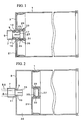
- Figures 1 through 4 show an embodiment of the container having means for preventing refilling employing a cap engaging member.
- numeral 1 denotes a container main body.
- the container main body 1 consists of a tubular body having a left end thereof as seen in the drawings closed by an end wall 3, and the end wall is centrally provided with a tubular opening 7 which defines a content taking out opening 5.
- a cap engaging tubular member 9 is internally received in the tubular opening 7.
- the cap engaging tubular member 9 comprises a flange portion 11 at its one end, a land portion 13 in its intermediate part, and a fluke-shaped engagement claw 15 around its other end or, in other words, around its forward end, the engagement claw 15 being elastically deformable in radial direction by being circumferentially separated from each other by slits 17 at its forward end.
- the cap engaging tubular member 9 can move between an initially filling position in which the land portion 13 abuts a bottom portion 19 of the tubular opening 7 as illustrated in Figure 1, and a normal position in which the flange portion 11 abuts the bottom portion 19 of the tubular opening 7 as illustrated in Figures 2 through 4, the projecting length of the engagement claw 15 from the end wall 3 being greater in the normal position than in the initial filling position.
- a piston member 21 is axially slidably received in the container main body 1, and a containing chamber 23 is defined between the piston member 21 and the end wall 3.
- the piston member 21 is centrally provided with a recess 25, and an opening 27 is provided in a bottom portion of the recess 25.
- a cap member 29 is fixedly fitted in the recess 25.
- the cap member 29 closes the opening 27 by being fitted into the recess 25 with a prescribed retaining force produced by a resistance imparting portion 31 so that the cap member 29 can be removed from the recess 25 and open up the opening 27 only when an axial force exceeding a prescribed value is applied thereto.
- a tubular engagement claw member 33 is fixedly fitted into the cap member 29.
- the engagement claw member 33 may be integrally formed with the cap member 29, but in the illustrated embodiment, is formed as a member separate from the cap member 29 for the convenience of the molding process.
- An engagement claw 35 is provided in the inner circumferential surface of an end of the engagement claw member 33 to be irreversibly engaged by the engagement claw 15 provided in the cap engaging tubular member 9.
- a content taking out tube 50 provided in an external device is fitted into the tubular opening 7 as shown by the imaginary lines in Figure 2, and the cap engaging member 9 is pushed to the right as seen in the drawings or at its normal position in which the flange portion 11 abuts the bottom portion 19 of the tubular opening 7 as illustrated in Figures 2 through 4.
- the content filled in the containing chamber 23 is taken out from the content taking out opening 5 provided in the tubular opening 7, and the piston member 21 moves to the right as seen in the drawings or toward the end wall 3 as the content is taken out.
- the piston member 21 When the content is all taken out from the containing chamber 23, the piston member 21 reaches its stroke end, and abuts the end wall 3 as illustrated in Figure 3. At this time, the engagement claw 15 of the cap engaging tubular member 9 fits into the engagement claw member 33, and irreversibly engages the engagement claw 35 of the engagement claw member 33. By this irreversible engagement between these two claws 15 and 35, the cap member 29 is held at this stroke end position.
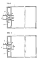
- Figures 5 and 6 show a second embodiment of the container having means for preventing refilling employing a cap engaging member and a breakable cap member according to the present invention.
- the parts corresponding to those in Figures 1 through 4 are denoted with like numerals.
- the cap member 29 substantially aligns with the content taking out opening 5 of the container main body 1, and substantially the entire bottom portion 30 of the cap member 29 is formed as a thin walled portion.
- the thin walled portion is denoted with numeral 30a in Figures 5 and 6.
- a thin walled substantially annular region may be provided around the side wall portion of the cap member 29.
- Figures 7 and 8 show a third embodiment of the container having means for preventing refilling employing a piston engaging member according to the present invention.
- Figures 5 and 6 the parts corresponding to those in Figures 1 through 6 are denoted with like numerals.
- a piston engaging tubular member 41 is internally received in the tubular opening 7.
- the piston engaging tubular member 41 is similar to the cap engaging tubular members 9 of the previous embodiments, and is provided with an engagement claw 43 around its forward end, and is capable of elastic deformation in radial direction by being circumferentially separated by slits 45 at its forward end.
- An annular engagement claw member 47 is fixedly fitted on the piston member 21.
- the engagement claw member 47 is formed with an engagement claw 49 which irreversibly engages with the engagement claw 43 of the piston engaging tubular member 43.
- the cap engaging member irreversibly engages the cap member, and retains the cap member at this position.
- the piston member moves away from the end wall as this refilling process progresses, and this causes the cap member to be removed from the piston member, and opens up the opening of the piston member. As a result, the content starts escaping from this opening.
- the piston engaging member irreversibly engages the piston member, and retains the piston member at this position.
- refilling of the content into the containing chamber from the content taking out opening is made possible.
Landscapes
- Engineering & Computer Science (AREA)
- Mechanical Engineering (AREA)
- Closures For Containers (AREA)
Applications Claiming Priority (2)
| Application Number | Priority Date | Filing Date | Title |
|---|---|---|---|
| JP189058/92 | 1992-07-16 | ||
| JP18905892 | 1992-07-16 |
Publications (2)
| Publication Number | Publication Date |
|---|---|
| EP0579492A1 true EP0579492A1 (fr) | 1994-01-19 |
| EP0579492B1 EP0579492B1 (fr) | 1996-10-09 |
Family
ID=16234590
Family Applications (1)
| Application Number | Title | Priority Date | Filing Date |
|---|---|---|---|
| EP93305531A Expired - Lifetime EP0579492B1 (fr) | 1992-07-16 | 1993-07-14 | Récipient présentant des moyens empêchant le réemplissage |
Country Status (3)
| Country | Link |
|---|---|
| US (1) | US5373969A (fr) |
| EP (1) | EP0579492B1 (fr) |
| DE (1) | DE69305268T2 (fr) |
Cited By (5)
| Publication number | Priority date | Publication date | Assignee | Title |
|---|---|---|---|---|
| EP0778147A3 (fr) * | 1995-12-04 | 1997-07-09 | Hewlett-Packard Company | Appareil et méthode de remplissage de cartouches d'encre |
| EP0685339A3 (fr) * | 1994-05-23 | 1997-07-23 | Canon Kk | Cartouche de réservoir d'encre et appareil de remplissage pour celle-ci. |
| WO2000006389A1 (fr) * | 1998-07-30 | 2000-02-10 | Casio Computer Co., Ltd. | Cartouche d'encre pour imprimante a jet d'encre et procede de production d'une pluralite de cartouches d'encre |
| EP1439075A3 (fr) * | 2003-01-14 | 2008-07-30 | Riso Kagaku Corporation | Réservoir d'encre pour sérigraphie, cartouche d'encre pour sérigraphie, procédé pour la fabrication d'une cartouche d'encre, et bouchon pour le réservoir d'encre |
| CN106739532A (zh) * | 2017-02-14 | 2017-05-31 | 厦门文仪电脑材料有限公司 | 一种油墨筒的活塞及具有该活塞的油墨筒 |
Families Citing this family (9)
| Publication number | Priority date | Publication date | Assignee | Title |
|---|---|---|---|---|
| US5560521A (en) * | 1995-03-06 | 1996-10-01 | Sonoco Products Company | Recyclable caulk cartridge with breakaway nozzle |
| US5681358A (en) * | 1995-09-29 | 1997-10-28 | Bloom & Kreten | Method of using an emergency fuel in an internal combustion engine |
| US6113660A (en) * | 1995-09-29 | 2000-09-05 | Leonard Bloom | Emergency fuel for use in an internal combustion engine and a method of packaging the fuel |
| DE19604626A1 (de) * | 1996-02-08 | 1997-08-14 | Uhu Gmbh | Klebstift mit kolbenförmiger Haltevorrichtung für die Stiftmasse |
| US5590590A (en) * | 1996-02-23 | 1997-01-07 | Edward Zammit | Implement for separating the liquid medium from the solid contents of canned foodstuffs |
| US6312072B1 (en) | 1997-05-01 | 2001-11-06 | Pitney Bowes Inc. | Disabling a printing mechanism in response to an out of ink condition |
| JPH1191784A (ja) * | 1997-09-22 | 1999-04-06 | Riso Kagaku Corp | 減容化容器 |
| NL2000634C2 (nl) * | 2007-05-07 | 2008-11-10 | Bema Kunststoffen B V | Houder en systeem voor het bewaren van een vloeistof. |
| WO2020152675A1 (fr) * | 2019-01-21 | 2020-07-30 | Twine Solutions Ltd. | Système de remplissage d'encre et de matériau de traitement ayant un seul réceptacle compatible avec de multiples cartouches d'encre |
Family Cites Families (8)
| Publication number | Priority date | Publication date | Assignee | Title |
|---|---|---|---|---|
| US996055A (en) * | 1910-10-18 | 1911-06-27 | New York & New Jersey Lubricant Company | Ejecting-container. |
| US1599660A (en) * | 1919-05-29 | 1926-09-14 | U S Sanitary Specialties Corp | Soap dispenser |
| JPS59153874U (ja) * | 1983-03-30 | 1984-10-16 | 株式会社吉野工業所 | クリ−ム状物収納容器 |
| US4949875A (en) * | 1986-02-18 | 1990-08-21 | Youti Kuo | Dispenser with integrated cover for paste-like material |
| DE3615659A1 (de) * | 1986-05-09 | 1987-11-12 | Hilti Ag | Auspresskolben mit speicherkammer |
| EP0351441A1 (fr) * | 1988-07-21 | 1990-01-24 | Alfred Fischbach Kunststoffspritzgusswerk | Cartouche pour masses plastiques |
| CA2027786C (fr) * | 1989-10-31 | 1997-01-28 | Koichi Sugita | Contenant muni d'une pompe |
| DE59103399D1 (de) * | 1990-06-21 | 1994-12-08 | Wilhelm A Keller | Austragkartusche mit Vorratszylinder und Förderkolben. |
-
1993
- 1993-07-14 US US08/091,204 patent/US5373969A/en not_active Expired - Lifetime
- 1993-07-14 EP EP93305531A patent/EP0579492B1/fr not_active Expired - Lifetime
- 1993-07-14 DE DE69305268T patent/DE69305268T2/de not_active Expired - Fee Related
Non-Patent Citations (1)
| Title |
|---|
| PATENT ABSTRACTS OF JAPAN vol. 010, no. 055 (M-458)5 March 1986 & JP-A-60 204 355 ( CANON ) * |
Cited By (8)
| Publication number | Priority date | Publication date | Assignee | Title |
|---|---|---|---|---|
| EP0685339A3 (fr) * | 1994-05-23 | 1997-07-23 | Canon Kk | Cartouche de réservoir d'encre et appareil de remplissage pour celle-ci. |
| US5946014A (en) * | 1994-05-23 | 1999-08-31 | Canon Kabushiki Kaisha | Ink tank cartridge and ink-filling device therefor |
| EP0778147A3 (fr) * | 1995-12-04 | 1997-07-09 | Hewlett-Packard Company | Appareil et méthode de remplissage de cartouches d'encre |
| WO2000006389A1 (fr) * | 1998-07-30 | 2000-02-10 | Casio Computer Co., Ltd. | Cartouche d'encre pour imprimante a jet d'encre et procede de production d'une pluralite de cartouches d'encre |
| US6345889B1 (en) | 1998-07-30 | 2002-02-12 | Casio Computer Co., Ltd. | Ink cartridge for ink jet printer and method of making the ink cartridge |
| EP1439075A3 (fr) * | 2003-01-14 | 2008-07-30 | Riso Kagaku Corporation | Réservoir d'encre pour sérigraphie, cartouche d'encre pour sérigraphie, procédé pour la fabrication d'une cartouche d'encre, et bouchon pour le réservoir d'encre |
| CN106739532A (zh) * | 2017-02-14 | 2017-05-31 | 厦门文仪电脑材料有限公司 | 一种油墨筒的活塞及具有该活塞的油墨筒 |
| CN106739532B (zh) * | 2017-02-14 | 2018-06-29 | 厦门文仪电脑材料有限公司 | 一种油墨筒的活塞及具有该活塞的油墨筒 |
Also Published As
| Publication number | Publication date |
|---|---|
| US5373969A (en) | 1994-12-20 |
| DE69305268T2 (de) | 1997-05-22 |
| EP0579492B1 (fr) | 1996-10-09 |
| DE69305268D1 (de) | 1996-11-14 |
Similar Documents
| Publication | Publication Date | Title |
|---|---|---|
| US5373969A (en) | Container having means for preventing refilling | |
| US5511698A (en) | Device for spraying a predetermined dose of a fluid, and a method of filling the device | |
| US5226882A (en) | Single-use syringe with non-retractable piston | |
| RU1828402C (ru) | Устройство дл инъекции лекарственных препаратов | |
| EP0378866A1 (fr) | Réceptacle | |
| US6056164A (en) | Container for stencil inks | |
| US3268123A (en) | Dispensers for fluent masses | |
| CA1303576C (fr) | Systeme d'alimentation/de remplissage, pour liquides | |
| US4392491A (en) | Injector | |
| US5078686A (en) | Single-use syringe | |
| US2866458A (en) | Hypodermic assembly | |
| SE467521B (sv) | Foerfylld spruta | |
| EP1646580B1 (fr) | Ensemble de bec retractable destine a des bouteilles | |
| JPH04239476A (ja) | 貯蔵シリンダと調合ピストンを備えた調合カートリッジ | |
| US6953449B2 (en) | Hypodermic syringe having plunger pull-out stopping structure | |
| US2687730A (en) | Ampoule | |
| US3437245A (en) | Powder dispenser | |
| EP0892915B1 (fr) | Seringue industrielle | |
| EP0208454A2 (fr) | Capsule pour vernis à ongles | |
| US3800979A (en) | Lpg valve assembly | |
| US4180173A (en) | Tamper-proof closure system | |
| US6976608B2 (en) | Cartridge charged with fluid materials and device for loading such cartridge to fluid dispensing apparatuses | |
| US5527286A (en) | Single-use syringe | |
| JP3387963B2 (ja) | 再充填防止容器 | |
| US5398847A (en) | Cylinder/piston type fluid container |
Legal Events
| Date | Code | Title | Description |
|---|---|---|---|
| PUAI | Public reference made under article 153(3) epc to a published international application that has entered the european phase |
Free format text: ORIGINAL CODE: 0009012 |
|
| 17P | Request for examination filed |
Effective date: 19930721 |
|
| AK | Designated contracting states |
Kind code of ref document: A1 Designated state(s): DE FR GB |
|
| 17Q | First examination report despatched |
Effective date: 19950926 |
|
| GRAG | Despatch of communication of intention to grant |
Free format text: ORIGINAL CODE: EPIDOS AGRA |
|
| GRAH | Despatch of communication of intention to grant a patent |
Free format text: ORIGINAL CODE: EPIDOS IGRA |
|
| GRAH | Despatch of communication of intention to grant a patent |
Free format text: ORIGINAL CODE: EPIDOS IGRA |
|
| GRAA | (expected) grant |
Free format text: ORIGINAL CODE: 0009210 |
|
| AK | Designated contracting states |
Kind code of ref document: B1 Designated state(s): DE FR GB |
|
| REF | Corresponds to: |
Ref document number: 69305268 Country of ref document: DE Date of ref document: 19961114 |
|
| ET | Fr: translation filed | ||
| PLBE | No opposition filed within time limit |
Free format text: ORIGINAL CODE: 0009261 |
|
| STAA | Information on the status of an ep patent application or granted ep patent |
Free format text: STATUS: NO OPPOSITION FILED WITHIN TIME LIMIT |
|
| 26N | No opposition filed | ||
| REG | Reference to a national code |
Ref country code: GB Ref legal event code: IF02 |
|
| PGFP | Annual fee paid to national office [announced via postgrant information from national office to epo] |
Ref country code: FR Payment date: 20090710 Year of fee payment: 17 |
|
| PGFP | Annual fee paid to national office [announced via postgrant information from national office to epo] |
Ref country code: GB Payment date: 20090708 Year of fee payment: 17 Ref country code: DE Payment date: 20090709 Year of fee payment: 17 |
|
| GBPC | Gb: european patent ceased through non-payment of renewal fee |
Effective date: 20100714 |
|
| REG | Reference to a national code |
Ref country code: FR Ref legal event code: ST Effective date: 20110331 |
|
| PG25 | Lapsed in a contracting state [announced via postgrant information from national office to epo] |
Ref country code: DE Free format text: LAPSE BECAUSE OF NON-PAYMENT OF DUE FEES Effective date: 20110201 |
|
| REG | Reference to a national code |
Ref country code: DE Ref legal event code: R119 Ref document number: 69305268 Country of ref document: DE Effective date: 20110201 |
|
| PG25 | Lapsed in a contracting state [announced via postgrant information from national office to epo] |
Ref country code: FR Free format text: LAPSE BECAUSE OF NON-PAYMENT OF DUE FEES Effective date: 20100802 |
|
| PG25 | Lapsed in a contracting state [announced via postgrant information from national office to epo] |
Ref country code: GB Free format text: LAPSE BECAUSE OF NON-PAYMENT OF DUE FEES Effective date: 20100714 |