EP0579544A1 - Verbundprofilanordnung wie Rinne oder dergleichen - Google Patents
Verbundprofilanordnung wie Rinne oder dergleichen Download PDFInfo
- Publication number
- EP0579544A1 EP0579544A1 EP93401821A EP93401821A EP0579544A1 EP 0579544 A1 EP0579544 A1 EP 0579544A1 EP 93401821 A EP93401821 A EP 93401821A EP 93401821 A EP93401821 A EP 93401821A EP 0579544 A1 EP0579544 A1 EP 0579544A1
- Authority
- EP
- European Patent Office
- Prior art keywords
- cover
- wings
- assembly according
- over
- profile assembly
- Prior art date
- Legal status (The legal status is an assumption and is not a legal conclusion. Google has not performed a legal analysis and makes no representation as to the accuracy of the status listed.)
- Granted
Links
- 239000002131 composite material Substances 0.000 title 1
- 229920002994 synthetic fiber Polymers 0.000 claims description 7
- 239000000463 material Substances 0.000 claims description 6
- 239000002023 wood Substances 0.000 claims description 5
- 230000005670 electromagnetic radiation Effects 0.000 abstract 1
- 230000000712 assembly Effects 0.000 description 5
- 238000000429 assembly Methods 0.000 description 5
- 239000011324 bead Substances 0.000 description 5
- 230000008901 benefit Effects 0.000 description 5
- 210000004027 cell Anatomy 0.000 description 4
- 239000011248 coating agent Substances 0.000 description 4
- 238000000576 coating method Methods 0.000 description 4
- 239000004020 conductor Substances 0.000 description 2
- 230000014759 maintenance of location Effects 0.000 description 2
- 238000004519 manufacturing process Methods 0.000 description 2
- 238000000465 moulding Methods 0.000 description 2
- 238000005192 partition Methods 0.000 description 2
- 238000007747 plating Methods 0.000 description 2
- 241000124892 Barbus Species 0.000 description 1
- 230000006978 adaptation Effects 0.000 description 1
- 239000000654 additive Substances 0.000 description 1
- 230000032683 aging Effects 0.000 description 1
- 210000000084 barbel Anatomy 0.000 description 1
- 238000005452 bending Methods 0.000 description 1
- 238000005524 ceramic coating Methods 0.000 description 1
- 238000010276 construction Methods 0.000 description 1
- 238000011109 contamination Methods 0.000 description 1
- 238000005034 decoration Methods 0.000 description 1
- 238000010292 electrical insulation Methods 0.000 description 1
- 238000009434 installation Methods 0.000 description 1
- 238000012423 maintenance Methods 0.000 description 1
- 239000004579 marble Substances 0.000 description 1
- 238000000034 method Methods 0.000 description 1
- 230000001681 protective effect Effects 0.000 description 1
- 125000006850 spacer group Chemical group 0.000 description 1
- 230000009897 systematic effect Effects 0.000 description 1
Images

Classifications
-
- H—ELECTRICITY
- H02—GENERATION; CONVERSION OR DISTRIBUTION OF ELECTRIC POWER
- H02G—INSTALLATION OF ELECTRIC CABLES OR LINES, OR OF COMBINED OPTICAL AND ELECTRIC CABLES OR LINES
- H02G3/00—Installations of electric cables or lines or protective tubing therefor in or on buildings, equivalent structures or vehicles
- H02G3/02—Details
- H02G3/04—Protective tubing or conduits, e.g. cable ladders or cable troughs
- H02G3/0406—Details thereof
- H02G3/0418—Covers or lids; Their fastenings
Definitions
- the present invention relates generally to profiled assemblies of the kind comprising a base and a cover snapped on by two wings on the base.
- Forming chutes, baseboards, moldings or the like, these profiled assemblies are usually used for housing electrical conductors, or even for housing electrical equipment, such as sockets or the like, served by such electrical conductors.
- Plating is a relatively expensive special technique.
- the present invention generally relates to a provision for overcoming these difficulties and also leading to other advantages.
- a profiled assembly of the kind comprising a base and a cover to be snapped on by two wings on this base, this profiled assembly being, according to a first aspect, generally characterized in that, the wings of the cover being elastically deformable, it further comprises, independently, an over-cover, which, itself having two wings, is to be snapped onto the cover by the latter.
- the desired coating is dissociated from its support, in this case the cover, to constitute by itself a self-supporting element, in this case an over-cover, which, initially distinct from the cover, is to be reported on at a later date.
- this cover is made of synthetic material.
- this elasticity advantageously allows systematic catching-up both of the inevitable manufacturing tolerances occurring from the outset between these elements and of equally inevitable games which are then liable to occur. develop in time between these.
- the cover assumes in this case an adaptation function, by absorbing any clearances and tolerances between the over-cover and it.
- the over-cover provided according to the invention can also advantageously assume by itself one or the other of several particular functions.
- this cover is produced in the usual way in an elastically deformable material, and, in practice, in synthetic material, the over-cover according to the invention can, for its part, be advantageously made in more rigid material, being therefore guarantor of the exterior geometry of the assembly.
- the base preferably further includes stop means, coming in one piece or attached, by which it buttresses itself the wings of the over-cover on the side of these opposite wings to the wings of the cover.
- these sub-covers which have not been established to extend longitudinally continuously over the entire length of the profiled assembly, extend transversely only over a fraction of the width of this profiled assembly, between internal partitions dividing it internally.
- the profiled assembly according to the invention is easier to manufacture, and ages better, than profiled assemblies of the same type on the lid and / or the base of which it is to date at least locally reported coating.
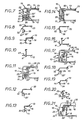
- the profiled assembly 10 comprises, in a manner known per se, in the manner for example of numerous chutes, plinths or moldings, on the one hand, a base 11, which, by a sole 12, is adapted to be applied to any support surface, for example a wall, and, on the other hand, a cover 13, which, by two wings 14, is to be snapped onto the base 11.
- the base 11 and the cover 13 are profiles with a U-shaped cross section suitable for being fitted one on the other.
- the base 11 has, in fact, longitudinally projecting from this sole 12, substantially perpendicular to the latter, two lateral flanges 15.
- these lateral flanges 15 extend back with respect to the longitudinal edges of the sole 12.
- the cover 13 has, in addition to its wings 14, a middle portion 16, which, in use, extends substantially parallel to the sole 12 of the base 11.
- the wings 14 extend along the same longitudinal edges of the middle part 16, by connecting to the latter by a rounded shape.
- these wings 14 extend, at rest, substantially perpendicular to the middle part 16, FIG. 4, and they run substantially over the entire height of the lateral flanges 15 of the base 11, Figures 1 and 6.
- the wings 14 of the cover 13 extend outside the lateral flanges 15 of the base 11, and means are provided for snap-fastening between them and these lateral flanges 15.
- these latching means comprise, on the one hand, a shoulder 18 provided in a recess on the lateral flanges 15 of the base 11, on the external surface of these lateral flanges 15, and, on the other hand, a shoulder 19 provided correspondingly projecting on the wings 14 of the cover 13, on the inner surface of these wings 14.
- the shoulder 18 of the lateral flanges 15 of the base 11 results from a crosstalk-shaped fold which these lateral flanges 15 present inwards, and the shoulder 19 of the wings 14 of the cover 13 results a rib which these projecting wings 14 project.
- the profiled assembly 10 further comprises, independently of this cover 13 and of the base 11, an over-cover 20 which, itself having two wings 22, is to be snapped onto the cover 13 by these wings 22.
- this over-cover 20 is in practice a U-shaped cross section.
- the wings 22 of the over-cover 20 extend directly along the same longitudinal edges of the middle part 23, by being connected to the latter by a rounded shape, and they run generally over the whole the height of the lateral flanges 15 of the base 11, up to the immediate vicinity of the sole 12 of this base 11.
- the base 11 is for example of synthetic material.
- cover 13 which is therefore made of elastically deformable material, and it follows that its wings 14 are themselves elastically deformable.
- the over-cover 20 is preferably made of more rigid material.
- the elasticity of the wings 14 of the cover 13 results at least in part from the fact that, at their connection to the middle part 16 which they border, they can play relative to this middle part 16, in the manner of a joint.
- the wings 14 of the cover 13 are in fact curved, in cross section, over at least part of their height, starting from their free edge, with the concavity of their corresponding curved part 25 turned towards the side. the middle part 16 which they border.
- the wings 22 of the over-cover 20 have a shoulder 26 projecting from their inner surface.
- this shoulder 26 belongs to a bead which runs along the free edge of these wings 22 projecting from the inner surface of the latter.
- the over-cover 20 is then snapped onto the cover 13.
- the wings 14 of the cover 13 have, in cross section, along their free edge, for their elasticity, beyond their curved part 25, a cusp part 28 directed inwards, in a general U-shape configuration for the whole.
- the base 11 includes abutment means by which it abuts the wings 22 of the over-cover 20 on the side of these wings 22 opposite the wings 14 of the cover 13.
- these abutment means consist of strips 29 that the base 11 presents laterally projecting from its sole 12, between the longitudinal edges of the latter and its lateral flanges 15 .
- these strips 29 extend obliquely to the sole 12, diverging from one another as they move away from this sole 12.
- the wings 22 of the over-cover 20 are divided into two portions, one 22 'inside, the other 22' 'outside, by which they respectively cover the slats 29 of the base 11 .
- the inner portion 22 extends inwardly inwardly relative to the current part of the wings 22, and it is it which carries the bead forming the shoulder 26 necessary for the locking of these wings 22 on the wings 14 of the cover 13.
- the outer portion 22 '' extends in continuity with the current part of the wings 22.
- the oblique portion of the strips 29 of the base 11 facilitates the engagement on them of the wings 22 of the over-cover 20.
- the wings 22 of the over-cover 20 carry by their inner portion 22 ′ against the strips 29 of the base 11 and are thus buttressed towards the inside by these.
- the elasticity of the wings 14 of the cover 13 results at least in part from at least one strip 32 that these wings 14 have projecting from the external surface.
- the inner portion 22 ′ of the wings 22 of the over-cover 20 has, staggered in height, for cooperation with one and / or the other of the strips 32 of the wings 14 of the cover 13, several beads each forming a shoulder 26 .
- the wings 22 of the over-cover 20 extend externally apparently over the entire height of the profile assembly 10.
- the wings 22 of the over-cover 20 only extend externally in an apparent manner over a portion of the height of the profiled assembly 10.
- these strips 29 extend directly along the same longitudinal edges of the sole 12 of the base 11, by being connected by a rounded shape thereto, in the manner, for aesthetics, of the rounding by which the wings 22 of the over-cover 20 are connected to the middle part 23 thereof.
- the lamellae 29 ′ of the base 11 constitute abutment means for the wings 22 of the over-cover 20, these wings 22 having, in recess inwardly relative to their current part, a portion 22 'through which they relate to these strips 29 '.
- the wings 14 of the cover 13 extend obliquely relative to the middle part 16 which they border, diverging with respect to one another as and as they move away from this middle part 16.
- these wings 14 are in practice bordered by a return 34, which, directed inwards, extends substantially parallel to the middle part 16.
- the corresponding shoulder 18 of these lateral flanges 15 is formed by the edge of a back 35 in the form of a butt which these lateral flanges 15 present obliquely outwards.
- the wings 22 of the over-cover 20 are divided into two portions 22 ', 22' ', for cooperation in support with lamellae 29 of the base 11.
- this snap-fitting is effected by engagement of this bead with the return 34 of the wings 14 of the cover 13.
- the obliquity of the wings 14 of the cover 13 advantageously facilitates the engagement of the over-cover 20 on the cover 13.
- the shoulder 26 of the wings 22 of the over-cover 20 is directly formed by the return by which the inner portion 22 'of these wings 22 is connected to the current part of these.
- the wings 22 of the over-cover 20 are generally oblique with respect to the middle part 23 which they border, in the manner of the wings 14 of the cover 13, except as regards the outer portion 22 '' which they present along their free edge, which remains straight, perpendicular to the sole 12 of the base 11.
Landscapes
- Engineering & Computer Science (AREA)
- Architecture (AREA)
- Civil Engineering (AREA)
- Structural Engineering (AREA)
- Acyclic And Carbocyclic Compounds In Medicinal Compositions (AREA)
- Medicinal Preparation (AREA)
- Footwear And Its Accessory, Manufacturing Method And Apparatuses (AREA)
- Moulding By Coating Moulds (AREA)
- Lining Or Joining Of Plastics Or The Like (AREA)
- Installation Of Indoor Wiring (AREA)
- Protection Of Pipes Against Damage, Friction, And Corrosion (AREA)
- Golf Clubs (AREA)
- Finishing Walls (AREA)
- Paper (AREA)
Applications Claiming Priority (2)
| Application Number | Priority Date | Filing Date | Title |
|---|---|---|---|
| FR929208837A FR2693849B1 (fr) | 1992-07-17 | 1992-07-17 | Ensemble profilé composite de type goulotte ou analogue. |
| FR9208837 | 1992-07-17 |
Publications (2)
| Publication Number | Publication Date |
|---|---|
| EP0579544A1 true EP0579544A1 (de) | 1994-01-19 |
| EP0579544B1 EP0579544B1 (de) | 1996-04-10 |
Family
ID=9431989
Family Applications (1)
| Application Number | Title | Priority Date | Filing Date |
|---|---|---|---|
| EP93401821A Expired - Lifetime EP0579544B1 (de) | 1992-07-17 | 1993-07-15 | Verbundprofilanordnung wie Rinne oder dergleichen |
Country Status (8)
| Country | Link |
|---|---|
| US (1) | US5406762A (de) |
| EP (1) | EP0579544B1 (de) |
| AT (1) | ATE136698T1 (de) |
| AU (1) | AU665834B2 (de) |
| DE (1) | DE69302144T2 (de) |
| ES (1) | ES2085737T3 (de) |
| FR (1) | FR2693849B1 (de) |
| ZA (1) | ZA935053B (de) |
Cited By (3)
| Publication number | Priority date | Publication date | Assignee | Title |
|---|---|---|---|---|
| US6770157B2 (en) | 2000-11-20 | 2004-08-03 | Valeo | Method and apparatus for adhesive fastening of friction clutch liners on a support plate |
| EP2148402A1 (de) * | 2008-07-22 | 2010-01-27 | Tehalit GmbH | Leitungsführungskanal für Energie- und Versorgungsleitungen |
| CN115450372A (zh) * | 2022-08-12 | 2022-12-09 | 中国电建集团贵阳勘测设计研究院有限公司 | 一种用于装配式建筑的线槽 |
Families Citing this family (35)
| Publication number | Priority date | Publication date | Assignee | Title |
|---|---|---|---|---|
| ES2065275B1 (es) * | 1993-06-14 | 1996-08-16 | Aparellaje Electrico Sa | Dispositivo de soporte de mecanismos electricos en canaletas para conducciones electricas. |
| FR2758016B1 (fr) * | 1996-12-31 | 1999-03-12 | Legrand Sa | Procede et dispositif pour affermir le maintien sur une goulotte d'un quelconque accessoire a rapporter par emboitement sur le socle de celle-ci |
| US5732747A (en) * | 1997-01-21 | 1998-03-31 | Icm Corporation | Cove molding cover for electrical cables |
| US5939670A (en) * | 1997-11-06 | 1999-08-17 | Scientific Technologies Incorporated | Trim structure for safetymat |
| US6244013B1 (en) * | 1999-10-05 | 2001-06-12 | Ming-Kun Lee | Combination grille for window |
| FR2806848B1 (fr) * | 2000-03-24 | 2002-06-21 | Legrand Sa | Accessoire a rapporter sur un socle de goulotte de cheminement de conducteurs ou de cables electriques |
| FR2810467B1 (fr) * | 2000-06-16 | 2003-01-10 | Planet Wattohm Sa | Dispositif de montage d'un appareil electrique sur un conduit de cablage |
| US6385939B1 (en) * | 2000-06-30 | 2002-05-14 | Marketing Displays, Inc. | Bullnose cladding system |
| WO2002002887A1 (en) * | 2000-06-30 | 2002-01-10 | Marketing Displays, Inc. | Bullnose cladding system |
| GB0104901D0 (en) * | 2001-02-28 | 2001-04-18 | Aggregate Ind Uk Ltd | Access ducting |
| DE20110280U1 (de) * | 2001-06-21 | 2001-08-23 | Keller Lichtsysteme GmbH, 72461 Albstadt | Unterputz-Installationsschiene |
| US6647681B1 (en) * | 2002-04-04 | 2003-11-18 | Jacquelyn J. Abbott | Decorative border and method for using same |
| US6748716B1 (en) * | 2003-04-04 | 2004-06-15 | Pawling Corporation | Impact-protecting wall guard |
| US7240637B2 (en) * | 2004-05-07 | 2007-07-10 | Rosen John B | Fence-covering system |
| US20060096203A1 (en) * | 2004-11-08 | 2006-05-11 | Weinstein Gary M | Two-part composite molding and trim with raceway |
| AT503205B1 (de) * | 2006-01-18 | 2007-11-15 | Anton Dipl Ing Zahradnik | Hüllen für kabelführungen |
| US7910829B2 (en) * | 2008-09-02 | 2011-03-22 | Bell'o International Corp. | Cable management system |
| US8079186B2 (en) * | 2008-12-22 | 2011-12-20 | Douglas Williams | Soffit system |
| US20100242389A1 (en) * | 2009-03-30 | 2010-09-30 | Robert Depaul | Corner wall conduit |
| US8534016B2 (en) * | 2009-03-30 | 2013-09-17 | Robert Depaul | Corner wall conduit |
| DE202009010674U1 (de) * | 2009-08-07 | 2010-12-23 | Tehalit Gmbh | Sockelleistenkanal mit Randkaschierung |
| US20210063836A1 (en) | 2017-04-26 | 2021-03-04 | View, Inc. | Building network |
| DE102010011506A1 (de) * | 2010-03-15 | 2011-09-15 | Fabian Eisler | Verkleidung eines handelsüblichen Kunststoff-Kabelkanales mittel eines spezill angepassen und verklebten Holzprofiles inkl. einer Bohrlehre und einer Montage-/Demontagevorrichtung |
| DE102012217815B4 (de) * | 2012-09-28 | 2016-12-29 | Obo Bettermann Gmbh & Co. Kg | Leitungskanal |
| US8984824B2 (en) * | 2012-10-29 | 2015-03-24 | James Hardie Technology Limited | Concealed fastening system for building finishing elements |
| US9938729B2 (en) * | 2013-03-15 | 2018-04-10 | Stephen A. Coon | System and method for an adjustable channel for an air conditioning line set |
| US20140338614A1 (en) * | 2013-05-17 | 2014-11-20 | Nicholas Carl Grubaugh | Modular track system for animals |
| US10813455B2 (en) * | 2014-12-17 | 2020-10-27 | Mccue Corporation | Bumper assembly |
| USD812782S1 (en) * | 2016-04-04 | 2018-03-13 | White Distribution, LLC | Self mating beam |
| US11467464B2 (en) | 2017-04-26 | 2022-10-11 | View, Inc. | Displays for tintable windows |
| US12339557B2 (en) | 2017-04-26 | 2025-06-24 | View, Inc. | Configuration associated with media display of a facility |
| US12603091B2 (en) | 2017-04-26 | 2026-04-14 | View Operating Corporation | Immersive collaboration of remote participants via media displays |
| USD877365S1 (en) * | 2017-12-22 | 2020-03-03 | Movomech Ab | Profile rail portion |
| US10790650B2 (en) | 2018-07-09 | 2020-09-29 | Icenine Industries, Llc | Conduit routing system |
| CA3169821A1 (en) * | 2020-09-30 | 2022-04-07 | View, Inc. | Display construct for media projection and wireless charging |
Citations (3)
| Publication number | Priority date | Publication date | Assignee | Title |
|---|---|---|---|---|
| CH556612A (fr) * | 1972-06-16 | 1974-11-29 | Kaiser Jean Entreprise General | Canal pour conducteurs electriques. |
| FR2473226A1 (fr) * | 1980-01-03 | 1981-07-10 | Villi Canalplast | Gaine porte-cables, notamment pour constructions privees et industrielles prefabriquees |
| EP0149377A1 (de) * | 1983-12-07 | 1985-07-24 | Legrand | Verbundkanal mit darauf angebrachtem(en) Element(en) insbesondere für die Aufnahme von elektrischen Kabeln |
Family Cites Families (2)
| Publication number | Priority date | Publication date | Assignee | Title |
|---|---|---|---|---|
| GB2191518A (en) * | 1986-07-10 | 1987-12-16 | Tanya May Eccleshall | Cornice system with covered joints |
| US5024614A (en) * | 1988-09-26 | 1991-06-18 | Amp Incorporated | Surface accessible wiring system and assembly |
-
1992
- 1992-07-17 FR FR929208837A patent/FR2693849B1/fr not_active Expired - Fee Related
-
1993
- 1993-07-12 US US08/089,373 patent/US5406762A/en not_active Expired - Lifetime
- 1993-07-13 ZA ZA933053A patent/ZA935053B/xx unknown
- 1993-07-15 EP EP93401821A patent/EP0579544B1/de not_active Expired - Lifetime
- 1993-07-15 AT AT93401821T patent/ATE136698T1/de not_active IP Right Cessation
- 1993-07-15 ES ES93401821T patent/ES2085737T3/es not_active Expired - Lifetime
- 1993-07-15 DE DE69302144T patent/DE69302144T2/de not_active Expired - Fee Related
- 1993-07-16 AU AU41967/93A patent/AU665834B2/en not_active Ceased
Patent Citations (3)
| Publication number | Priority date | Publication date | Assignee | Title |
|---|---|---|---|---|
| CH556612A (fr) * | 1972-06-16 | 1974-11-29 | Kaiser Jean Entreprise General | Canal pour conducteurs electriques. |
| FR2473226A1 (fr) * | 1980-01-03 | 1981-07-10 | Villi Canalplast | Gaine porte-cables, notamment pour constructions privees et industrielles prefabriquees |
| EP0149377A1 (de) * | 1983-12-07 | 1985-07-24 | Legrand | Verbundkanal mit darauf angebrachtem(en) Element(en) insbesondere für die Aufnahme von elektrischen Kabeln |
Cited By (4)
| Publication number | Priority date | Publication date | Assignee | Title |
|---|---|---|---|---|
| US6770157B2 (en) | 2000-11-20 | 2004-08-03 | Valeo | Method and apparatus for adhesive fastening of friction clutch liners on a support plate |
| EP2148402A1 (de) * | 2008-07-22 | 2010-01-27 | Tehalit GmbH | Leitungsführungskanal für Energie- und Versorgungsleitungen |
| CN115450372A (zh) * | 2022-08-12 | 2022-12-09 | 中国电建集团贵阳勘测设计研究院有限公司 | 一种用于装配式建筑的线槽 |
| CN115450372B (zh) * | 2022-08-12 | 2023-10-03 | 中国电建集团贵阳勘测设计研究院有限公司 | 一种用于装配式建筑的线槽 |
Also Published As
| Publication number | Publication date |
|---|---|
| AU665834B2 (en) | 1996-01-18 |
| DE69302144T2 (de) | 1996-08-29 |
| ZA935053B (en) | 1994-02-07 |
| ES2085737T3 (es) | 1996-06-01 |
| DE69302144D1 (de) | 1996-05-15 |
| FR2693849B1 (fr) | 1994-09-30 |
| EP0579544B1 (de) | 1996-04-10 |
| AU4196793A (en) | 1994-01-20 |
| US5406762A (en) | 1995-04-18 |
| FR2693849A1 (fr) | 1994-01-21 |
| ATE136698T1 (de) | 1996-04-15 |
Similar Documents
| Publication | Publication Date | Title |
|---|---|---|
| EP0579544B1 (de) | Verbundprofilanordnung wie Rinne oder dergleichen | |
| EP0149377B1 (de) | Verbundkanal mit darauf angebrachtem(en) Element(en) insbesondere für die Aufnahme von elektrischen Kabeln | |
| EP1276197A1 (de) | Zusatz für Kabelrinnen mit Abschnitten unterschiedlicher Höhe | |
| FR2825527A1 (fr) | Accessoire d'angle pour goulotte | |
| EP1324892A1 (de) | Verwendung von verglasung mit einem profiliertem band zu seiner installation in einer öffnung | |
| WO2007003823A2 (fr) | Dispositif de fixation d'un profile enjoliveur sur un cordon profile | |
| EP1149447B1 (de) | Gerätegehalter ,insbesondere für elektrisches gerät und damit ausgerüstetes gehäuse | |
| EP0851551B1 (de) | Verfahren und Vorrichtung zum Verbessern des Haltens eines Zubehörs mit Schnappbefestigung an einem Kabelrinnensockel | |
| EP1139535B1 (de) | Zubehör für elektrischen Verkabelungskanalsockel | |
| FR2952144A1 (fr) | Joint de finition adapte pour etre fixe entre deux vitrages et vehicule automobile comportant deux vitrages separes par un interstice comportant un tel joint de finition. | |
| EP0607083B1 (de) | Kabelrinnezusatz und Rinne ausgerustet mit einem solchem Zusatz | |
| FR2947109A1 (fr) | Console destinee a la solidarisation d'un chemin de cables a un poteau | |
| EP1164676B1 (de) | Vorrichtung zur Befestigung eines elektrischen Geräts auf einem Kabelkanal | |
| FR2656390A1 (fr) | Dispositif de liaison entre deux profiles. | |
| EP0611871B1 (de) | Ausrichteckwinkel für Metallfensterrahmen | |
| EP0320343B1 (de) | Abdichtungselement, insbesondere Firstabdichtung, mit biegsamen Dichtungsstreifen | |
| FR2509361A1 (fr) | Cadre d'adaptation realise en profiles, pour vitrage | |
| EP1211773B1 (de) | Träger für ein Gerät, inbesondere für ein elektrisches Gerät, zur Befestigung auf einem Kabelkanalkörper | |
| EP2570566A2 (de) | Fugenabdeckungsvorrichtung für Bodenbelag | |
| EP0887903B1 (de) | Sockel für Kabelkanal mit einem V-förmigen Querschnitt, insbesondere Eckkanal oder Unterputzkanal | |
| EP0102431A1 (de) | Vorgefertigtes Element für Eindeckungsplatten, insbesondere für Dächer | |
| EP2615709B1 (de) | Elektrisches Gerät für Einbaugehäuse | |
| EP1246333A1 (de) | Endstück für einen Führungskanal | |
| EP2770132B1 (de) | Rahmen eines kastens, der abdichtmittel umfasst, und mit einem solchen rahmen versehener kasten | |
| FR3002257A1 (fr) | Ensemble a lames du type positionnable sur un plan support, piece de fixation mise en œuvre dans ledit ensemble, revetement comprenant au moins ledit ensemble et procede de fixation d'un tel ensemble a un plan support |
Legal Events
| Date | Code | Title | Description |
|---|---|---|---|
| PUAI | Public reference made under article 153(3) epc to a published international application that has entered the european phase |
Free format text: ORIGINAL CODE: 0009012 |
|
| AK | Designated contracting states |
Kind code of ref document: A1 Designated state(s): AT BE DE ES GB IT NL SE |
|
| 17P | Request for examination filed |
Effective date: 19940129 |
|
| 111L | Licence recorded |
Free format text: 0100 LEGRAND SNC |
|
| 17Q | First examination report despatched |
Effective date: 19950809 |
|
| GRAH | Despatch of communication of intention to grant a patent |
Free format text: ORIGINAL CODE: EPIDOS IGRA |
|
| GRAA | (expected) grant |
Free format text: ORIGINAL CODE: 0009210 |
|
| AK | Designated contracting states |
Kind code of ref document: B1 Designated state(s): AT BE DE ES GB IT NL SE |
|
| REF | Corresponds to: |
Ref document number: 136698 Country of ref document: AT Date of ref document: 19960415 Kind code of ref document: T |
|
| ITF | It: translation for a ep patent filed | ||
| REF | Corresponds to: |
Ref document number: 69302144 Country of ref document: DE Date of ref document: 19960515 |
|
| REG | Reference to a national code |
Ref country code: ES Ref legal event code: FG2A Ref document number: 2085737 Country of ref document: ES Kind code of ref document: T3 |
|
| GBT | Gb: translation of ep patent filed (gb section 77(6)(a)/1977) |
Effective date: 19960503 |
|
| PLBE | No opposition filed within time limit |
Free format text: ORIGINAL CODE: 0009261 |
|
| STAA | Information on the status of an ep patent application or granted ep patent |
Free format text: STATUS: NO OPPOSITION FILED WITHIN TIME LIMIT |
|
| 26N | No opposition filed | ||
| REG | Reference to a national code |
Ref country code: GB Ref legal event code: IF02 |
|
| PGFP | Annual fee paid to national office [announced via postgrant information from national office to epo] |
Ref country code: AT Payment date: 20030616 Year of fee payment: 11 |
|
| PGFP | Annual fee paid to national office [announced via postgrant information from national office to epo] |
Ref country code: SE Payment date: 20030618 Year of fee payment: 11 |
|
| PGFP | Annual fee paid to national office [announced via postgrant information from national office to epo] |
Ref country code: NL Payment date: 20030619 Year of fee payment: 11 |
|
| PGFP | Annual fee paid to national office [announced via postgrant information from national office to epo] |
Ref country code: BE Payment date: 20030812 Year of fee payment: 11 |
|
| PG25 | Lapsed in a contracting state [announced via postgrant information from national office to epo] |
Ref country code: AT Free format text: LAPSE BECAUSE OF NON-PAYMENT OF DUE FEES Effective date: 20040715 |
|
| PG25 | Lapsed in a contracting state [announced via postgrant information from national office to epo] |
Ref country code: SE Free format text: LAPSE BECAUSE OF NON-PAYMENT OF DUE FEES Effective date: 20040716 |
|
| PG25 | Lapsed in a contracting state [announced via postgrant information from national office to epo] |
Ref country code: BE Free format text: LAPSE BECAUSE OF NON-PAYMENT OF DUE FEES Effective date: 20040731 |
|
| BERE | Be: lapsed |
Owner name: *LEGRAND Effective date: 20040731 |
|
| PG25 | Lapsed in a contracting state [announced via postgrant information from national office to epo] |
Ref country code: NL Free format text: LAPSE BECAUSE OF NON-PAYMENT OF DUE FEES Effective date: 20050201 |
|
| EUG | Se: european patent has lapsed | ||
| NLV4 | Nl: lapsed or anulled due to non-payment of the annual fee |
Effective date: 20050201 |
|
| BERE | Be: lapsed |
Owner name: *LEGRAND Effective date: 20040731 |
|
| PGFP | Annual fee paid to national office [announced via postgrant information from national office to epo] |
Ref country code: ES Payment date: 20090723 Year of fee payment: 17 |
|
| PGFP | Annual fee paid to national office [announced via postgrant information from national office to epo] |
Ref country code: GB Payment date: 20090703 Year of fee payment: 17 Ref country code: DE Payment date: 20090716 Year of fee payment: 17 |
|
| PGFP | Annual fee paid to national office [announced via postgrant information from national office to epo] |
Ref country code: IT Payment date: 20090718 Year of fee payment: 17 |
|
| GBPC | Gb: european patent ceased through non-payment of renewal fee |
Effective date: 20100715 |
|
| PG25 | Lapsed in a contracting state [announced via postgrant information from national office to epo] |
Ref country code: DE Free format text: LAPSE BECAUSE OF NON-PAYMENT OF DUE FEES Effective date: 20110201 |
|
| REG | Reference to a national code |
Ref country code: DE Ref legal event code: R119 Ref document number: 69302144 Country of ref document: DE Effective date: 20110201 |
|
| PG25 | Lapsed in a contracting state [announced via postgrant information from national office to epo] |
Ref country code: IT Free format text: LAPSE BECAUSE OF NON-PAYMENT OF DUE FEES Effective date: 20100715 |
|
| PG25 | Lapsed in a contracting state [announced via postgrant information from national office to epo] |
Ref country code: GB Free format text: LAPSE BECAUSE OF NON-PAYMENT OF DUE FEES Effective date: 20100715 |
|
| REG | Reference to a national code |
Ref country code: ES Ref legal event code: FD2A Effective date: 20110818 |
|
| PG25 | Lapsed in a contracting state [announced via postgrant information from national office to epo] |
Ref country code: ES Free format text: LAPSE BECAUSE OF NON-PAYMENT OF DUE FEES Effective date: 20100716 |