EP0579880A1 - Herstellungsverfahren für einen Schlägerrahmen - Google Patents
Herstellungsverfahren für einen Schlägerrahmen Download PDFInfo
- Publication number
- EP0579880A1 EP0579880A1 EP92306692A EP92306692A EP0579880A1 EP 0579880 A1 EP0579880 A1 EP 0579880A1 EP 92306692 A EP92306692 A EP 92306692A EP 92306692 A EP92306692 A EP 92306692A EP 0579880 A1 EP0579880 A1 EP 0579880A1
- Authority
- EP
- European Patent Office
- Prior art keywords
- annular recess
- head frame
- frame
- moulding tool
- racket frame
- Prior art date
- Legal status (The legal status is an assumption and is not a legal conclusion. Google has not performed a legal analysis and makes no representation as to the accuracy of the status listed.)
- Withdrawn
Links
- 238000004519 manufacturing process Methods 0.000 title claims abstract description 8
- 239000000463 material Substances 0.000 claims abstract description 17
- 239000004033 plastic Substances 0.000 claims abstract description 17
- 229920003023 plastic Polymers 0.000 claims abstract description 17
- 238000000465 moulding Methods 0.000 claims abstract description 16
- 229910000838 Al alloy Inorganic materials 0.000 claims abstract description 13
- 239000004840 adhesive resin Substances 0.000 claims abstract description 3
- 229920006223 adhesive resin Polymers 0.000 claims abstract description 3
- 238000000034 method Methods 0.000 claims description 6
- OKTJSMMVPCPJKN-UHFFFAOYSA-N Carbon Chemical compound [C] OKTJSMMVPCPJKN-UHFFFAOYSA-N 0.000 claims description 4
- 229910052799 carbon Inorganic materials 0.000 claims description 4
- 239000004744 fabric Substances 0.000 claims description 4
- 239000000835 fiber Substances 0.000 claims description 4
- 239000011248 coating agent Substances 0.000 claims description 2
- 238000000576 coating method Methods 0.000 claims description 2
- 238000004080 punching Methods 0.000 claims description 2
- 229920005989 resin Polymers 0.000 claims description 2
- 239000011347 resin Substances 0.000 claims description 2
- 229920001187 thermosetting polymer Polymers 0.000 claims description 2
- 239000003822 epoxy resin Substances 0.000 description 5
- 229920000647 polyepoxide Polymers 0.000 description 5
- 238000005336 cracking Methods 0.000 description 2
- 230000000694 effects Effects 0.000 description 1
- 239000000203 mixture Substances 0.000 description 1
Images



Classifications
-
- A—HUMAN NECESSITIES
- A63—SPORTS; GAMES; AMUSEMENTS
- A63B—APPARATUS FOR PHYSICAL TRAINING, GYMNASTICS, SWIMMING, CLIMBING, OR FENCING; BALL GAMES; TRAINING EQUIPMENT
- A63B60/00—Details or accessories of golf clubs, bats, rackets or the like
- A63B60/02—Ballast means for adjusting the centre of mass
-
- A—HUMAN NECESSITIES
- A63—SPORTS; GAMES; AMUSEMENTS
- A63B—APPARATUS FOR PHYSICAL TRAINING, GYMNASTICS, SWIMMING, CLIMBING, OR FENCING; BALL GAMES; TRAINING EQUIPMENT
- A63B49/00—Stringed rackets, e.g. for tennis
- A63B49/02—Frames
- A63B49/12—Frames made of metal
-
- A—HUMAN NECESSITIES
- A63—SPORTS; GAMES; AMUSEMENTS
- A63B—APPARATUS FOR PHYSICAL TRAINING, GYMNASTICS, SWIMMING, CLIMBING, OR FENCING; BALL GAMES; TRAINING EQUIPMENT
- A63B49/00—Stringed rackets, e.g. for tennis
- A63B49/02—Frames
- A63B2049/0217—Frames with variable thickness of the head in the string plane
-
- A—HUMAN NECESSITIES
- A63—SPORTS; GAMES; AMUSEMENTS
- A63B—APPARATUS FOR PHYSICAL TRAINING, GYMNASTICS, SWIMMING, CLIMBING, OR FENCING; BALL GAMES; TRAINING EQUIPMENT
- A63B60/00—Details or accessories of golf clubs, bats, rackets or the like
- A63B60/48—Details or accessories of golf clubs, bats, rackets or the like with corrugated cross-section
Definitions
- This invention relates to a method of making a game racket frame, and more particularly to a method of making a racket frame made of an aluminium alloy and provided with a weight-balancing system.
- a racket frame especially a tennis racket frame
- weight-balancing pieces fastened respectively to the mid-point of the left-hand half of the head frame and to the mid-point of the right-hand half of the head frame, so as to enhance the inertia of the racket and to prevent the racket from twisting upon hitting a ball.
- weight-balancing pieces fastened securely to a head frame of an aluminium alloy.
- a method of making a game racket frame comprising the steps of:
- the present invention makes it possible to provide a method of making a game racket frame made of aluminium alloy, provided with weight-balancing pieces, which are securely fastened to the head frame.
- each annular recess has two first step portions located respectively at both ends thereof and has a second step portion located between the two first step portions.
- each annular recess is provided with a plurality of cavities.
- a surface region at a junction between the head frame and the annular recess is provided with a plurality of serrated grooves before the racket frame is placed in the moulding tool.
- the cavity of the moulding tool has a wall provided with a bridging layer made of a carbon fibre fabric preimpregnated with a thermosetting resin and located at a position corresponding to the annular recess.
- each annular recess is provided with a plurality of ducts at the time when the annular recess is punched.
- a racket 10 made of an aluminium alloy tubular body embodied in the present invention is shown to comprise a head frame 12 and a shaft 14.
- a punched annular recess 20 of a predetermined length is provided at the mid-point of the left-hand half of the head frame 12 and a similar recess 22 (not shown) at the mid-point of the right-hand half of the head frame 12.
- the annular recesses 20 and 22 are coated with epoxy resin.
- a moulding tool 30 comprises a male mould 31 and a female mould 32 which between them define a mould cavity 34, which has a size larger than the head frame 12 and also has a widened portion 36 facing the inner side of the annular recess 20 or 22.
- the moulding tool 30 surrounding the racket head frame 12 in the regions of the annular recesses 20 and 22, a plastics material mixed with an epoxy resin is injected into each mould cavity 34.
- the racket frame 10 is removed from the moulding tool 30.
- the racket frame 10 so made is provided with the head frame 12 having weight-balancing pieces 16 and 18, which are located respectively at the mid-point of the left-hand of the head frame 12 and at the mid-point of the right-hand half of the head frame 12.
- the weight-balancing pieces 16 and 18 are securely fastened to the head frame 12 by virtue of the facts that they are held securely to the annular recesses 20 and 22 and that they are securely adhered to the surfaces of the annular recesses 20 and 22 by means of a mixture containing the plastic material and the epoxy resin.
- the weights of the weight-balancing pieces 16 and 18 can be adjusted in accordance with the sizes of the annular recesses 20 and 22 and of the mould cavity 34, and with the density of the injected plastic material.
- the annular recesses equivalent to the recesses 20 and 22 of Figure 2 are provided respectively with first step portions 201 and 221 and with second step portions 202 and 222 located in an intermediate region of the first step portions 201 and 221.
- a bridging layer 38 made from carbon fibre fabric preimpregnated in epoxy resin is attached to the mould cavity wall located in a position corresponding to the first step portions 201 and 221.
- the annular recesses 20 and 22 are each placed in the mould cavity 34, into which a molten plastics material is injected, so that the gap between the cured bridging layer 38 and the wall of the mould cavity 34 is filled in by the injected plastics material.
- the weight-balancing pieces 16 and 18 are securely and intimately adhered to the annular recesses 20 and 22.
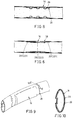
- the annular recesses 20 and 22 are further provided with a plurality of cavities 24 or ducts 26, into which the injected plastics material flows and anchors, as shown in Figures 7 and 8.
- a plurality of serrated grooves 28 of the various lengths are constructed at the junction surface between the head frame 12 and the annular recesses 20 and 22, so as to allow the injected plastics material to flow and anchor thereinto.
- an uneven junction line is formed in the junction between the weight-balancing pieces 16 and 18 and the head frame 12, as shown in Figures 9 and 10.
- Such structures as described above serve to avert the cracking of the junction area between the weight-balancing pieces 16 and 18 and the annular recesses 20 and 22.
- serrated grooves 28 of an equal length may be disposed in or adjacent the annular recesses 20 and 22, which are provided respectively with the first and the second step portions 201, 221, 202 and 222.
- a bridging layer 40 which is made of carbon fibre fabric preimpregnated in epoxy resin, is attached to the wall of mould cavity 34 opposite to each of serrated grooves 28 and each of the first step portions 201 and 221.
- Such a bridging layer 40 is embedded in the serrated groove 28 upon completion of the curing process thereof. As a result, the junction area between the weight-balancing pieces 16 and 18 and the head frame 12 is further reinforced.
Landscapes
- Health & Medical Sciences (AREA)
- General Health & Medical Sciences (AREA)
- Physical Education & Sports Medicine (AREA)
- Injection Moulding Of Plastics Or The Like (AREA)
Priority Applications (1)
| Application Number | Priority Date | Filing Date | Title |
|---|---|---|---|
| EP92306692A EP0579880A1 (de) | 1992-07-22 | 1992-07-22 | Herstellungsverfahren für einen Schlägerrahmen |
Applications Claiming Priority (1)
| Application Number | Priority Date | Filing Date | Title |
|---|---|---|---|
| EP92306692A EP0579880A1 (de) | 1992-07-22 | 1992-07-22 | Herstellungsverfahren für einen Schlägerrahmen |
Publications (1)
| Publication Number | Publication Date |
|---|---|
| EP0579880A1 true EP0579880A1 (de) | 1994-01-26 |
Family
ID=8211442
Family Applications (1)
| Application Number | Title | Priority Date | Filing Date |
|---|---|---|---|
| EP92306692A Withdrawn EP0579880A1 (de) | 1992-07-22 | 1992-07-22 | Herstellungsverfahren für einen Schlägerrahmen |
Country Status (1)
| Country | Link |
|---|---|
| EP (1) | EP0579880A1 (de) |
Cited By (4)
| Publication number | Priority date | Publication date | Assignee | Title |
|---|---|---|---|---|
| EP0898988A3 (de) * | 1997-08-22 | 1999-04-14 | Dunlop Slazenger Group Limited | Spielschläger |
| CN104069628A (zh) * | 2013-03-28 | 2014-10-01 | 邓禄普体育用品株式会社 | 球拍框架 |
| CN113069741A (zh) * | 2021-04-28 | 2021-07-06 | 上海迎轩体育科技有限公司 | 羽毛球拍稳固型三通装置制备工艺 |
| US20230021604A1 (en) * | 2021-07-22 | 2023-01-26 | Wei-Jung Chen | Shock absorbing device |
Citations (2)
| Publication number | Priority date | Publication date | Assignee | Title |
|---|---|---|---|---|
| FR91118E (fr) * | 1966-07-15 | 1968-04-19 | Nouvelle raquette pour jeux et son procédé de fabrication | |
| US5054780A (en) * | 1990-08-30 | 1991-10-08 | Dennis Chen | Weight adjustable tennis racquet |
-
1992
- 1992-07-22 EP EP92306692A patent/EP0579880A1/de not_active Withdrawn
Patent Citations (2)
| Publication number | Priority date | Publication date | Assignee | Title |
|---|---|---|---|---|
| FR91118E (fr) * | 1966-07-15 | 1968-04-19 | Nouvelle raquette pour jeux et son procédé de fabrication | |
| US5054780A (en) * | 1990-08-30 | 1991-10-08 | Dennis Chen | Weight adjustable tennis racquet |
Cited By (5)
| Publication number | Priority date | Publication date | Assignee | Title |
|---|---|---|---|---|
| EP0898988A3 (de) * | 1997-08-22 | 1999-04-14 | Dunlop Slazenger Group Limited | Spielschläger |
| US6030302A (en) * | 1997-08-22 | 2000-02-29 | Dunlop Slazenger Group Limited | Games rackets |
| CN104069628A (zh) * | 2013-03-28 | 2014-10-01 | 邓禄普体育用品株式会社 | 球拍框架 |
| CN113069741A (zh) * | 2021-04-28 | 2021-07-06 | 上海迎轩体育科技有限公司 | 羽毛球拍稳固型三通装置制备工艺 |
| US20230021604A1 (en) * | 2021-07-22 | 2023-01-26 | Wei-Jung Chen | Shock absorbing device |
Similar Documents
| Publication | Publication Date | Title |
|---|---|---|
| US6800234B2 (en) | Method for making a molded polymeric article | |
| US7703179B2 (en) | Microreplicated surface | |
| EP1337382B1 (de) | Verfahren und vorrichtung zur herstellung eines nassrasiererhandgriffes | |
| CA2684027C (en) | Compression mold and molding process | |
| US4451041A (en) | Golf club head and a method for manufacturing the same | |
| US7914403B2 (en) | Hockey stick | |
| EP3097960B1 (de) | Hockeyschlägerblatt mit logosystem sowie coformverfahren | |
| US4451042A (en) | Golf club head of carbon fiber reinforced plastic | |
| CA2428925C (en) | One-piece shaft construction and a method of construction using bladder molding | |
| US11534669B2 (en) | Hockey stick with spine-reinforced paddle | |
| US5220719A (en) | Method of making game racket frame | |
| EP1145664A2 (de) | Pinsel mit einstellbarer Bürstenendhülse und Herstellungsverfahren | |
| US20020169033A1 (en) | Method of making an article having a high moment of inertia and the article thus produced | |
| EP2133125B1 (de) | Schaft für einen Sportstock | |
| WO2005060726A1 (en) | Insert-molded synthetic resin spade and method of manufacturing the same | |
| JPS5923224B2 (ja) | インジエクシヨンラケットの製造方法 | |
| US20250381460A1 (en) | Piece of sports equipment for transmitting force | |
| BE1008451A3 (nl) | Racket en werkwijze voor het vervaardigen van zulke racket. | |
| CA1186880A (en) | Method of making a racket frame | |
| JPH0679019A (ja) | ラケットフレームの製造方法 | |
| JPS54104940A (en) | Method of shaping racket frame having outer shell reinforcing layer | |
| JPH07204294A (ja) | ラケットフレーム | |
| TW290490B (en) | Manufacturing method for the head of golf club made of composite material | |
| JPS5928978A (ja) | ゴルフクラブの製造方法 | |
| Hogarth et al. | Molded article and method and apparatus for making same |
Legal Events
| Date | Code | Title | Description |
|---|---|---|---|
| PUAI | Public reference made under article 153(3) epc to a published international application that has entered the european phase |
Free format text: ORIGINAL CODE: 0009012 |
|
| AK | Designated contracting states |
Kind code of ref document: A1 Designated state(s): AT BE CH DE DK ES FR GB GR IT LI LU MC NL PT SE |
|
| STAA | Information on the status of an ep patent application or granted ep patent |
Free format text: STATUS: THE APPLICATION IS DEEMED TO BE WITHDRAWN |
|
| 18D | Application deemed to be withdrawn |
Effective date: 19940727 |