EP0580016B1 - Réseau local - Google Patents
Réseau local Download PDFInfo
- Publication number
- EP0580016B1 EP0580016B1 EP93110816A EP93110816A EP0580016B1 EP 0580016 B1 EP0580016 B1 EP 0580016B1 EP 93110816 A EP93110816 A EP 93110816A EP 93110816 A EP93110816 A EP 93110816A EP 0580016 B1 EP0580016 B1 EP 0580016B1
- Authority
- EP
- European Patent Office
- Prior art keywords
- frame
- operation network
- local operation
- station
- network according
- Prior art date
- Legal status (The legal status is an assumption and is not a legal conclusion. Google has not performed a legal analysis and makes no representation as to the accuracy of the status listed.)
- Expired - Lifetime
Links
- 238000000034 method Methods 0.000 claims description 24
- 238000012360 testing method Methods 0.000 claims description 21
- 230000001360 synchronised effect Effects 0.000 claims description 12
- 230000005540 biological transmission Effects 0.000 claims description 10
- 238000012545 processing Methods 0.000 claims description 5
- 230000003287 optical effect Effects 0.000 description 23
- 230000000875 corresponding effect Effects 0.000 description 9
- 230000008901 benefit Effects 0.000 description 7
- 238000009826 distribution Methods 0.000 description 7
- 238000011161 development Methods 0.000 description 6
- 230000018109 developmental process Effects 0.000 description 6
- 239000013307 optical fiber Substances 0.000 description 5
- 230000008569 process Effects 0.000 description 5
- 238000012549 training Methods 0.000 description 5
- 238000004891 communication Methods 0.000 description 4
- 239000003365 glass fiber Substances 0.000 description 4
- 239000007787 solid Substances 0.000 description 3
- 238000012546 transfer Methods 0.000 description 3
- 230000032683 aging Effects 0.000 description 2
- 230000008859 change Effects 0.000 description 2
- 230000007480 spreading Effects 0.000 description 2
- 238000003892 spreading Methods 0.000 description 2
- 101100172132 Mus musculus Eif3a gene Proteins 0.000 description 1
- 230000003213 activating effect Effects 0.000 description 1
- 230000006978 adaptation Effects 0.000 description 1
- 238000006243 chemical reaction Methods 0.000 description 1
- 238000010276 construction Methods 0.000 description 1
- 230000001276 controlling effect Effects 0.000 description 1
- 230000002596 correlated effect Effects 0.000 description 1
- 230000008878 coupling Effects 0.000 description 1
- 238000010168 coupling process Methods 0.000 description 1
- 238000005859 coupling reaction Methods 0.000 description 1
- 230000001934 delay Effects 0.000 description 1
- 230000001419 dependent effect Effects 0.000 description 1
- 238000013461 design Methods 0.000 description 1
- 238000001514 detection method Methods 0.000 description 1
- 238000010586 diagram Methods 0.000 description 1
- 238000005516 engineering process Methods 0.000 description 1
- 239000000835 fiber Substances 0.000 description 1
- 238000003780 insertion Methods 0.000 description 1
- 230000037431 insertion Effects 0.000 description 1
- 238000004519 manufacturing process Methods 0.000 description 1
- 230000007246 mechanism Effects 0.000 description 1
- 238000012544 monitoring process Methods 0.000 description 1
Images
Classifications
-
- H—ELECTRICITY
- H04—ELECTRIC COMMUNICATION TECHNIQUE
- H04J—MULTIPLEX COMMUNICATION
- H04J3/00—Time-division multiplex systems
- H04J3/02—Details
- H04J3/06—Synchronising arrangements
- H04J3/0635—Clock or time synchronisation in a network
- H04J3/0638—Clock or time synchronisation among nodes; Internode synchronisation
- H04J3/0652—Synchronisation among time division multiple access [TDMA] nodes, e.g. time triggered protocol [TTP]
-
- H—ELECTRICITY
- H04—ELECTRIC COMMUNICATION TECHNIQUE
- H04J—MULTIPLEX COMMUNICATION
- H04J3/00—Time-division multiplex systems
- H04J3/02—Details
- H04J3/06—Synchronising arrangements
- H04J3/0635—Clock or time synchronisation in a network
- H04J3/0638—Clock or time synchronisation among nodes; Internode synchronisation
-
- H—ELECTRICITY
- H04—ELECTRIC COMMUNICATION TECHNIQUE
- H04J—MULTIPLEX COMMUNICATION
- H04J3/00—Time-division multiplex systems
- H04J3/02—Details
- H04J3/06—Synchronising arrangements
- H04J3/0635—Clock or time synchronisation in a network
- H04J3/0682—Clock or time synchronisation in a network by delay compensation, e.g. by compensation of propagation delay or variations thereof, by ranging
-
- H—ELECTRICITY
- H04—ELECTRIC COMMUNICATION TECHNIQUE
- H04L—TRANSMISSION OF DIGITAL INFORMATION, e.g. TELEGRAPHIC COMMUNICATION
- H04L12/00—Data switching networks
- H04L12/28—Data switching networks characterised by path configuration, e.g. LAN [Local Area Networks] or WAN [Wide Area Networks]
- H04L12/44—Star or tree networks
-
- B—PERFORMING OPERATIONS; TRANSPORTING
- B60—VEHICLES IN GENERAL
- B60R—VEHICLES, VEHICLE FITTINGS, OR VEHICLE PARTS, NOT OTHERWISE PROVIDED FOR
- B60R16/00—Electric or fluid circuits specially adapted for vehicles and not otherwise provided for; Arrangement of elements of electric or fluid circuits specially adapted for vehicles and not otherwise provided for
- B60R16/02—Electric or fluid circuits specially adapted for vehicles and not otherwise provided for; Arrangement of elements of electric or fluid circuits specially adapted for vehicles and not otherwise provided for electric constitutive elements
- B60R16/03—Electric or fluid circuits specially adapted for vehicles and not otherwise provided for; Arrangement of elements of electric or fluid circuits specially adapted for vehicles and not otherwise provided for electric constitutive elements for supply of electrical power to vehicle subsystems or for
- B60R16/0315—Electric or fluid circuits specially adapted for vehicles and not otherwise provided for; Arrangement of elements of electric or fluid circuits specially adapted for vehicles and not otherwise provided for electric constitutive elements for supply of electrical power to vehicle subsystems or for using multiplexing techniques
Definitions
- the invention relates to a local Operation network, which has a number of subscribers, each via a bus line with a central Star couplers are connected, being from a subscriber sent message via the central star coupler to all Participants of the local operations network is directed.
- Such a local operations network for the automotive sector is known from DE-OS 35 06 118.
- the the asynchronous bus access method used here is a Carrier-sensing multiple access method with Collision detection (CSMA / CD), in which an access conflict two or more participants by one Arbitration mechanism is solved at the bit level.
- CSMA / CD Carrier-sensing multiple access method with Collision detection
- a disadvantage of the known operation network is that it is not flexible is enough to meet the increased demands in the automotive industry Range.
- a modern local operations network should not only be the standard in the automotive sector a data accruing to every automobile to guarantee the Functionality of the car and for function group monitoring and control are transferred. Rather, everyone offers well-known Automobile manufacturers - to meet the needs of customers wear - a range of special equipment. It is therefore In addition to the standard data, a number of other data about the local operation network to transfer which to control which special equipment is required or during operation of these additional devices.
- equipping one Automobiles with such special equipment then occur Problem on that this on different models different places must be attached. Thereby different signal propagation times occur from model to model between these participants and the central star coupler.
- the well-known automotive local Operations network does not allow this different and depending on the model, varying signal transit times wear. It is therefore strong in its area of application limited and therefore not universally applicable.
- an optical network which has a central Distribution device includes, to which several nodes are connected. Each node is connected to the central distribution facility via n lines connected; n corresponds to the number of connected nodes.
- the Nodes send messages to the central via a line Distribution device.
- the central distribution device distributes the received ones Messages from all nodes via n lines to all n nodes. On Node is selected as the reference node. All other nodes synchronize themselves to the reference node so that all of the n nodes sent messages arrive synchronously at the distribution facility.
- the distribution device distributes the messages received synchronously synchronously to all nodes, to each node via n lines.
- the invention presents itself Task, a local operations network of the type mentioned in such a way that it is more universally applicable.
- a local operations network in particular in that a Frame clock generator one through a sequence of data frames Defined bit length specified frame clock sends that this Frame clock is routed to the central star coupler that the Time sequence of the data frames of the frame clock in the central Star coupler one the signal processing of the others Determine participants of the local operations network
- Reference frame clock defines that the other participants of the local operation network each an individual Determine frame send clock, so that each of one message sent to certain participants taking into account the signal runtime from the sending participant to the central Star coupler in the latter at the time relative to the Reference frame clock arrives, for which this message in the in central star coupler to include existing data frames, and that the one containing the messages from the participants Data frame is routed to all participants.
- the individual Participants in the local operations network the time at which they send their messages to the central star coupler, taking into account the signal runtime from the sending Determine participants for the central star coupler.
- This Measure is in a particularly advantageous manner guarantees that the messages of the sending participants are accurate arrive at the central star coupler at the time they can be inserted into the data frame without complications.
- the determination of the Signal runtime between sending participant and central Star coupler is done individually for each participant, so that a change in the transmission path can be detected dynamically is.
- This individual, dynamic signal delay compensation has the advantage that the local operations network according to the invention is flexible in Regarding the arrangement of the participants in the local Operations network is what makes it universal results.
- the individual and dynamic Signal delay compensation also has the advantage that Signs of aging on the transmission links slightly can be compensated.
- the frame send clock individual participants on a central reference frame clock related which is preferably from a as "Master participant” acting participant of the local Operation network is generated implicitly.
- Another advantageous development of the invention provides that as a frame clock generator a participant of the bus system acts. It is also advantageous that in addition to this "Master participant" at least one other participant of the hardware of the local operation network is that it is subsidiary to the role of the frame clock generator can take over. This is the case with the local operation network according to the invention provided that this subsidiary "master participant” in turn sends a frame clock identifier if it doesn't within a certain time interval after activating the restaurant Operation network a frame rate of the primary "master participant” receives. However, all participants are preferably local Operations network able to play the role of the primary To be able to take over the "master participant". Through this Measure according to the invention is particularly advantageous and achieved increased system security.
- each participant for signal delay compensation and thus to determine its frame end clock relative to its Frame reception clock sends out a test sequence and the duration determines which elapses before it is received. In this manner and way is a particularly simple determination of the Signal runtime possible, from which the Frame send clock can be determined.
- An advantageous development of the invention provides that each participant in the local operations network after the Switching on the operating voltage performs a self-test, which ensures that all components are faultless function. This measure advantageously and secured way that only fully functional participants system communication of the local Participate in the operations network.
- Another advantageous development of the invention provides that the data frames mediate a synchronous service synchronous frame module and an asynchronous service transmitting have asynchronous frame module.
- This hybrid Data frame structure allows it in a particularly advantageous manner and way, within a single data frame of the operation network according to the invention both synchronous and to transmit asynchronous services, making the universal Field of application of the operation network according to the invention still further is increased.
- Another advantageous development of the invention provides that participants in the local operations network via a secondary star coupler to the central star coupler are connected. This measure according to the invention has the Advantage that the number of transmission lines is drastic is reduced.
- At least one participant in the local operations network is designed as a multiplexer / demultiplexer. This allows it in advantageous way that several on this participant connected information sources and / or information sinks can be combined into a modular unit.
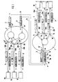
- the embodiment shown in Figure 1 of a local Operation network has an optical central star coupler 1, on the glass fibers acting as bus lines 10a, 10b, 20a, 20b and 30a, 30b three participants 10, 20 and 30 are connected. Furthermore, the optical central Star coupler 1 via additional glass fibers 2a, 2b an optical one secondary star coupler 2 connected, which in turn via optical fibers 40a, 40b, 50a, 50b and 60a, 60b with three Participants 40, 50 and 60 of the local operations network connected is.
- the central star coupler 1 is designed such that a optical signal occurring at one of its inputs 1a-1d all outputs 1a'-1d 'is routed. E.g. is that from that first participant 10 via the optical fiber 10a to the entrance 1a guided optical signal to both the input 1a correlated output 1a 'as well as to the other outputs 1b'-1d '. The same applies to the second and third participants 20 and 30 as well as for the secondary Star coupler 2.
- the secondary one Star coupler 2 designed such that one on any Input 2a'-2d 'signal occurring to output 2d ", that is to say Output, which is connected to the central star coupler 1, is directed.
- an am Output 1d 'of the central star coupler 1 occurring and over the optical fiber 2a to the input 2a 'of the secondary star coupler 2 passed signal to the outputs 2b "-2d", which with the Coupled 40-60 participants of the local operations network are directed.
- the to the central star coupler 1 and the secondary Star coupler 2 connected participants 10-60 of the local Operation network serve to any electrical and / or logical relationships of the downstream of these participants, Information sources and / or sinks not shown in Figure 1 to the local operations network operating on an optical basis adapt.
- Participants in the local operations network are different Forms of training possible.
- Each participant 10-60 owns only exemplary character and is not to be understood as that the function assigned to a particular subscriber is the Generality of the considerations made in this list restricted.
- the first participant 10 is a universal interface trained, which serves the connection between any digital or analog sensors / actuators (not shown) on the one hand and any other Sources or sinks of information from the local operations network to manufacture. So he sets the ones generated by the sensors sensor-specific signals into optical data signals, which in local operations network are capable of spreading. On the other hand the first subscriber 10 also serves to inform him about the optical fibers of the local operations network optical data signals into the specific actuator signals to implement.
- it is particularly easy to already known sensor / actuator modules without a special one Adaptation to couple them to the local operations network.
- the other participants 20-60 are special interfaces executed that optimal for a special application are adjusted.
- the second subscriber 20 is as CAN interface and is used to integrate a external CAN bus. Works within these external CAN buses the second participant 20 as an equal CAN participant and represents within this through the CAN bus system formed the receiving station, which after the arrival of a CAN bus signal, an acknowledge field in enters the CAN bus protocol. On the part of the optical local operation networks it acts as a transmitter, i.e. the second subscriber 20 can receive signals which he receives via the local operations network to the stations of his Pass on the CAN island.
- the second subscriber 20 acting as a CAN interface is trained in such a way that it receives all signals from the CAN island or the optical local operations network Can be made available, edited. So that's it second participant 20 in a particularly simple manner possible to use the existing sensors / actuators on the ISO standard CAN based, in the described local Integrate operations network.
- the third participant 30 is designed as a FIFO interface and serves as a data acquisition unit, the externally supplied Record and cache information and serial over can forward the optical network.
- the fourth subscriber 40 takes in audio / video signals via one Figure 1 not shown antenna input and puts it in optical data signals around in the optical local Operations network are capable of spreading. He also serves to that from the fiber optics of the local operations network the fourth subscriber 40 guided optical data signals convert such that they are not for those in Figure 1 shown audio / video terminals, which on the fourth subscriber 40th are connected, can be processed. Since the described local operations network is provided by a Optical data signals fed into the network the fourth points to all other participants Participants 40 further establishments that it him allow the data signals supplied by other participants, which are important for audio / video use edit and control comfort functions of the Use audio / video end devices. As an example, be here the speed-dependent control of the volume of a Car radios mentioned in as a control variable for raising or Lowering the volume level the driving speed of the Automobile arrives.
- the fifth subscriber 50 acts as a communication interface, which mobile radio signals (GSM, DCS 1800, DECT), which over a antenna input, not shown in FIG. 1, for the fifth Participants 50 get into the signal format of the local Operations network implements or those transmitted by this optical data signals in for the fifth participant 50th connected terminal devices converted back significant signals.
- GSM mobile radio signals
- DCS 1800, DECT mobile radio signals
- the sixth participant 60 is a valve interface designed. It allows the connection of a central one Display unit (not shown) and provides all necessary Sensor signals available on the operation network ready to display.
- the one tailored to the specific area of application Training the above Participants advantageously allow the subscriber stations of the local operations network in particular Training inexpensively, which is an inexpensive Realization of the same results.
- Training participants 10-60 of the local Operation network continues to depend on whether through it only a single end device in the local operations network should be involved, or whether over a certain Participants 10-60 a plurality of end devices to the local Operations network to be coupled. In the former Case it is sufficient to have the participants 10-60 like this train that he - as described - the implementation of the Terminal-specific signals in the data format of the local Operations network or vice versa.
- the corresponding participant 10-60 as Form multiplexer / demultiplexer, which by means of a known multiplexing method in the local operation network signals to be fed in from the connected end devices prepared accordingly or by the local operations network optical data signals routed to the particular subscriber demultiplexed into the terminal-specific signals.
- the participant 10-60 of the local Operation network an internal communication on it connected terminal devices, so that a modular Construction is achieved.
- this Frame reference clock is chosen the time grid, which by the arrival of those generated by the first participant 10 Data frame is set in the central star coupler 1. All remaining participants 20-60 focus their signal processing on the Reference frame clock such that taking into account the Signal propagation times from the corresponding subscriber 20-60 to central star coupler 1 the timely arrival of their Message (see above) is guaranteed. In detail, this happens like follows:
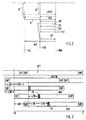
- the first subscriber 10 acting as a frame clock generator generates a data frame 3 defined by bit length Frame identifiers SOF and EOF (see Figure 3) marked and is limited.
- the data frame 3 generated at the time T0-v10 then arrives at central star coupler 1 at time T0.
- the variable v10 denotes the signal transit time between the first participant 10 on the one hand and the central Star coupler 1, on the other hand.
- the first adds Participant 10 its towards the local operations network transmitting message D in the data frame 3, wherein it is assumed that the first subscriber 10 has a fourth Segment 3d of the data frame divided into six segments 3a-3f 3 is assigned.
- the division of data frame 3 into six Segments 3a-3f is not necessarily physical Nature.
- the frame identifier characterizing the start of a data frame 3 SOF reaches the central star coupler 1 after one Signal runtime from v10. This time T0 - the arrival of the Frame identifier SOF of the one generated by the first subscriber 10 Data frame 3 - is now used as the reference time for the entire Signal processing defined in the local operations network. The same applies to the subsequent data frame 3 Data frame so that the generated by the first participant 10 through the sequence of data frame 3 fixed frame clock one Reference frame clock of the local operations network of the local Operations network defined.
- the second subscriber In order to ensure that the message E to be transmitted by the second subscriber 20 arrives at the point in time at which it is to be inserted in the central star coupler 1 into the fifth segment 3e of the data frame 3 generated by the first subscriber 10, the second subscriber send its data information to be fed into the local operation network at the time T0-v20 + e, where v20 denotes the signal delay between the second subscriber 20 and the central star coupler 1 and e the relative position of the fifth segment 3e in the data frame.
- the third subscriber 30 must send his message F at a time T0-v30 + f if he wants to ensure that it is included in the fifth segment 3f of the data frame 3 assigned to him.
- the variable v30 denotes the signal transit time between the third subscriber 30 on the one hand and the central star coupler 1 on the other hand.
- the relative position of the fifth segment 3f in the data frame 3 is again designated by f.
- the fourth, fifth and sixth participants 40.50 and 60 the data transmission at times T0-v0-v40, T0-v0-v50 + b and T0-v0-v60 + c must initiate if guaranteed should be that the corresponding messages A, B and C in the first, second and third segments 3a, 3b and 3c of the data frame 3 can be written.
- the variables denote v40, v50 and v60 the signal delays between the fourth, fifth and sixth participants 40, 50 and 60 on the one hand and the secondary Star coupler 2, on the other hand.
- the variable v0 then denotes the Runtime of the signals between the secondary star coupler 2 and the primary star coupler 1. With b and c is again relative position of the segments 3b and 3c in the data frame 3 guaranteed.
- participant - central star coupler 1 the data without an explicit frame structure be transmitted. This is shown by the dashed lines in FIG shown data frame 3, which is only the For the sake of clarity and to show the relative position of messages A, B, C, E and F have been drawn.
- the one specified by the first subscriber 10 The frame structure is used by these via the frame IDs SOF and EOF recognized. This is due to the chronological order of the received Data frame 3 'predetermined time grid is considered Frame reception clock of the receiving participants 10-60 defined.
- the data frame 3 'now hits - as can be seen from FIG. 1 is - at the times T0 + v0 + v40 or T0 + v0 + v50 or T0 + v0 + v60 for the fourth, fifth and sixth participants 40-60 and over the times T0 + v10 or T0 + v20 or T0 + v30 at the first or second and third participants 10-30 of the local Operations network. Since here a data frame 3 'with explicit frame structure is transmitted, this is in figure 1 shown in solid lines.
- each participant 10-60 of the local operations network carried out Before the actual synchronization procedure of the individual Participants 10-60 of the local operations network carried out is provided that each participant 10-60 one Carries out self-test. This must ensure that all of his electrical and optical components perfectly function. The implementation of such a self-test as well as its hardware implementation is the expert known, so that further explanations at this point spare. This self-test is advantageous and Way ensured that only fully functional participants in the System communication within the local Operations network.
- the local Operation network is configured in an advantageous manner and every time you restart.
- the first step is the actual synchronization procedure the participant who acts as a frame clock generator is determined, sends the frame clock and thus implicitly the reference frame clock generated.
- this task hardware a single participant of the local Operations network is assigned. This possibility draws through their particularly inexpensive hardware Implementation.
- the local is particularly advantageous To equip the operation network with self-organization, i.e. that several or preferably all participants 10-60 such are designed to perform the function of the frame clock generator can take over.
- This multiple design increases the System security considerably, because in the event of the failure of one or multiple participants the remaining participants of the local Operations network are capable of self-configuration and self-organization for the still functional part of the local operations network.
- a hierarchical Sequence of individual participants 10-60 is set, such that a lower-ranking participant has the function of Frame clock generator takes over if it is within a defined time interval no frame clock identification of a hierarchically higher-level participant receives.
- the first subscriber 10 sends a "hello” signal, which in Figure 2 represented by the solid arrow "H” is.
- the second subscriber 20 receives the "hello” signal. This is shown in Figure 2 by the from the line BUS to the time axis t20 second participant 20 extending, drawn solid Arrow “HE” shown. This causes the second now Participant 20 begins to synchronize, i.e. the second Participant 20 determines its signal transit time v20 to the central one Star coupler 1. This determination of the signal transit time is now with reference to Figure 2 and in particular Figure 3 explained.
- the second subscriber 20 determines from the data frames 3 ' limiting frame identifiers SOF and EOF Frame receive clock RET ( Figure 3) and sends relative to this Frame reception clock RET a test sequence TS to the central Star coupler 1.
- This test sequence TS is used in this Time inserted there data frame 3 and in Data frame 3 'is routed back to the second subscriber 20. This process is shown in Figure 2 by the dashed arrow TSE shown.
- the second participant 20 now determines from the Time difference between sending and receiving the test sequence TS the signal runtime v20 and then shifts its Frame send clock RST ( Figure 3) accordingly, so that a Reference frame clock synchronized frame send clock RST20 (FIG 3) is set.
- the second subscriber 20 After completing these steps, i.e. after completion its synchronization procedure, the second subscriber 20 sends a signal "hello 2" to the bus, which in Figure 2 by the solid arrow H2 is shown. This signal becomes H2 via the central star coupler 1 to the first subscriber 10 headed. This process is shown in Figure 2 by the arrow HE2 shown. With the receipt of the signal "hello 2" by the The first participant 10 is the second participant 20 in the local operations network "logged in” and thus configured.
- the second participant 20 sends out a second test sequence TS1 (FIG. 2) and again receives, so that the first determination of the signal transit time v20 verify or a faulty or failed first To be able to repeat the determination.
- the first determination of Signal runtime v20 can fail especially if that Test signal TS is superimposed by frame identifiers SOF or EOF.
- the second subscriber 20 has a unique one Determination not possible. It sends - as mentioned - a second one Test sequence shifted in time so that this on arrival guaranteed between the frame IDs SOF and EOF.
- a such procedure is particularly in High-speed data networks are an advantage because they have the exact determination of the signal transit times and the based on them Signal delay compensation of considerable importance for the the local operations network functions properly.
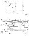
- the arrival of a "hello" signal H at a participant 30-60 causes a timer to start. After the expiry of the time interval T determined by the timer begins corresponding participants with its synchronization procedure. It is provided that the number of timer starts that between the "hello" signal H sent by the subscriber 10 and the start of a particular synchronization procedure Participants pass, varies from participant to participant. By staggering the time of the individual Synchronization procedures is achieved that the successful completion of the synchronization procedure identifying participant messages do not overlap. So is - As can be seen from Figure 4 - provided that the second Participants immediately after receiving the "hello" signal H of the first participant in the synchronization procedure Time interval T carries out and after its expiration Subscriber identifier H2 sends to the first subscriber.
- the third Participant 30 begins its synchronization procedure - Which in Figure 4 by a dashed circular Arrow is shown symbolically - only after the first Time interval T and accordingly leads this Synchronization procedure during a subsequent second Time interval T through. Accordingly, the sixth and waits so that the last participant 60 of the local operations network five timer starts, each time T, from and only begins with it in a sixth time interval T. Synchronization procedure. When they are finished, he sends in Signal "hello 6" (represented by the arrow H6 in FIG. 4) first participant 10.
- the above description of the local Operation network and its synchronization are from the special internal structure of the data frame used 3 independently.
- data frame 3 which is a synchronous services mediating synchronous frame module and an asynchronous service mediating asynchronous frame module
- the through a division module generated by the first participant 10 Distribution of the data frame 3 is dynamically variable.
- this data frame structure is particularly special advantageous way possible both synchronous and transfer asynchronous services in a single data frame, whereby a particularly universal use of the Operation network results.
- Such a modular structure of a Data frame is in the parallel application "frame structured Bus system "described by the same applicant, to which hereby explicit reference is made.
- FIG. 5 there is now a transmitting / receiving part 100 of a subscriber shown which is for use with the described local operation network particularly suitable is.
- the transmitting / receiving part has an O / E converter 101, which led to the conversion of those via the optical fiber 102 optical data signals into electrical signals.
- the O / E converter 101 is one clocked by an oscillator 109 Synchronization circuit 110 downstream, which the Frame reception clock determined or it during operation controlled.
- the synchronization circuit 110 is with a functional block 120 connected, which for determining the signal transit time and thus the required delay time of the frame send clock serves for the reference frame clock.
- a functional block 120 connected, which for determining the signal transit time and thus the required delay time of the frame send clock serves for the reference frame clock.
- the Function block 120 determines the Function block 120 by determining the time difference between the transmission and the arrival of the test signal TS ( Figure 2 and Figure 3) the signal transit time to the central Star coupler 1 and accordingly controls an oscillator 109 clocked delay element 121.
- the delay element 121 acts with a clocked by the oscillator 109 Frame structure generator / monitor 130 together, which the Frame IDs SOF and EOF generated.
- the synchronization circuit 110 is also a Module selector 140 connected.
- the module selector 140 carries out the appropriate division of the received data frame 3 'into synchronous and the asynchronous frame module.
- the Module selector 140 is connected to a demultiplexer 151, which as Interface to those connected to the participant Sources of information or sinks work.
- the module selector 140 is also one of one Microprocessor-controlled access control 150 connected, which in connection with the module selector 140 the reception and in conjunction with another module selector 140a Sends the asynchronous frame module controls.
- the Microprocessor 160 also controls the Frame structure generator / monitor 130 for generating the Frame structure.
- a multiplexer 170 serves as another interface to the Information sources / sinks of the participant.
- An I / O converter 171 converts the electrical signals of the transmitter / receiver unit into optical signals, which are in the local operations network are spreadable.
Landscapes
- Engineering & Computer Science (AREA)
- Computer Networks & Wireless Communication (AREA)
- Signal Processing (AREA)
- Small-Scale Networks (AREA)
Claims (23)
- Réseau opérationnel local présentant un certain nombre d'abonnés (10-60) qui sont reliés respectivement à travers une ligne de bus (10a, 10b; 20a, 20b; 30a, 30b; 40a, 2a, 40b, 2b; 50a, 2a, 50b, 2b; 60a, 2a, 60b, 22b) à un coupleur en étoile central (1) pour acheminer un message envoyé par un abonné (10-60) à travers le coupleur en étoile central (1) à tous les abonnés (10-60) du réseau opérationnel local, caractérisé en ce qu'un générateur d'horloge de trame est prévu qui est capable de générer et d'émettre une horloge de trame (RT) déterminée par une série de trames de données (3) de longueur binaire définie, en ce que le coupleur en étoile central (1) est capable de recevoir l'horloge de trame (RT) et de définir à partir de la séquence dans le temps des trames de données (3) de l'horloge de trame (RT) une horloge de trame de référence déterminant le traitement de signal des abonnés (10-60) du réseau opérationnel local, en ce que les abonnés (20-60) sont respectivement capables de déterminer une horloge d'émission de trame (RST) individuelle de telle sorte que le message (B-F) envoyé respectivement par un certain abonné (20-60) atteint, en tenant compte du temps de propagation de signal entre l'abonné émetteur (20-60) et le coupleur en étoile central (1), ce dernier à un instant défini par rapport à l'horloge de trame de référence avec laquelle ce message (B-F) doit être intégré dans la trame de données présente dans le coupleur en étoile central (1), et en ce que le coupleur en étoile central (1) est capable d'acheminer la trame de données (3') contenant les messages (A-F) des abonnés (10-60) à tous les abonnés (10-60).
- Réseau opérationnel local selon la revendication 1, caractérisé en ce que le temps de propagation de signal (v20-v60) entre chacun des abonnés (20-60) et le coupleur en étoile central (1) peut être déterminé de façon dynamique à chaque démarrage du réseau opérationnel, et en ce que l'horloge d'émission de trame de l'abonné (20-60) peut être décalée dans le temps en fonction du temps de propagation de signal déterminé par rapport à son horloge de réception de trame (RET).
- Réseau opérationnel local selon la revendication 1 ou 2, caractérisé en ce que pour la détermination du temps de propagation de signal (v20-v60), chaque abonné (20-60) est capable d'envoyer un signal de test (TS) au coupleur en étoile central (1), en ce que ce signal de test (TS) peut être réacheminé à l'abonné émetteur (20-60) dans la trame de données envoyée (3'), en ce que l'abonné émetteur est capable de déterminer le temps de propagation de signal (v20-v60) à partir de la différence de temps entre l'envoi et l'arrivée du signal de test (TS, TSE).
- Réseau opérationnel local selon la revendication 1, caractérisé en ce que les messages (A-F) des abonnés (10-60) individuels peuvent être insérés dans la trame de données (3) de façon séquentielle.
- Réseau opérationnel local selon la revendication 1, caractérisé en ce qu'au démarrage du système de bus, chaque abonné (10-60) est capable de réaliser un test automatique pour vérifier ses différents composants.
- Réseau opérationnel local selon la revendication 5, caractérisé en ce que le test automatique peut être surveillé dans le temps.
- Réseau opérationnel local selon la revendication 1, caractérisé en ce qu'un abonné (10) servant de générateur d'horloge de trame peut générer des identifications de trame (SOF, EOF) qui identifient le début et la fin d'une trame de données (3).
- Réseau opérationnel local selon la revendication 7, caractérisé en ce que l'arrivée de l'identification de trame (SOF) identifiant le début d'une trame de données (3) au coupleur en étoile central (1) permet de déterminer un instant de référence (TO).
- Réseau opérationnel local selon l'une quelconque des revendications 1 à 8, caractérisé en ce que la trame de données (3) comprend un module de trame synchrone transmettant des services synchrones et un module de trame asynchrone transmettant des services asynchrones, et en ce que la répartition de la trame de données (3) en ces deux modules de trame peut être modifiée de façon dynamique.
- Réseau opérationnel local selon la revendication 9, caractérisé en ce que la répartition de la trame de données (3) est effectuée par un module de séparation pouvant être déplacé de façon dynamique qui est généré dans le générateur d'horloge de trame, ou en ce que la répartition de la trame de données (3) est indiquée par un pointeur apparaissant à son début.
- Réseau opérationnel local selon l'une quelconque des revendications 1 à 10, caractérisé en ce que la fonction du générateur d'horloge de trame est affectée à un certain abonné (10) du système de bus du réseau opérationnel local.
- Réseau opérationnel local selon l'une quelconque des revendications 1 à 11, caractérisé en ce que la fonction du générateur d'horloge de trame peut être récupérée à la mise en service ou au moment d'une reconfiguration après une panne auprès d'au moins un autre abonné (20-60), une séquence hiérarchique des abonnés individuels étant déterminée à l'intérieur du réseau de sorte qu'un abonné (20-60) de rang inférieur prend en charge la fonction du générateur d'horloge de trame si, à l'intérieur d'un intervalle de temps défini, il ne reçoit aucune identification d'horloge de trame provenant d'un abonné (10) de niveau hiérarchique supérieur.
- Réseau opérationnel local selon la revendication 12, caractérisé en ce que chaque abonné (10-60) du réseau opérationnel peut prendre en charge la fonction du générateur d'horloge de trame.
- Réseau opérationnel local selon la revendication 11, 12 ou 13, caractérisé en ce que l'abonné (10) prenant en charge la fonction du générateur d'horloge de trame envoie un signal (H) aux autres abonnés (20-60) du réseau opérationnel local qui inhibe leur prise en charge de la fonction de générateur d'horloge de trame.
- Réseau opérationnel local selon l'une quelconque des revendications 1 à 14, caractérisé en ce que l'abonné (10) servant de générateur d'horloge de trame est capable d'envoyer un signal (H) aux autres abonnés (20-60) qui déclenche chez eux le démarrage d'un temporisateur, et en ce que les autres abonnés sont capables d'effectuer la détermination de leur horloge d'émission de trame (RST) après expiration d'un intervalle de temps (T) spécifique à l'abonné et déterminé par le temporisateur.
- Réseau opérationnel local selon la revendication 15, caractérisé en ce que les autres abonnés (20-60) sont capables d'envoyer à l'abonné (10) servant de générateur d'horloge de trame une identification d'abonné (H2, H6) après achèvement de leur procédure de synchronisation.
- Réseau opérationnel local selon la revendication 1, caractérisé en ce qu'au moins un abonné (10-60) du réseau opérationnel local est connecté au coupleur en étoile central (1) par au moins un coupleur en étoile secondaire (2).
- Réseau opérationnel local selon la revendication 17, caractérisé en ce qu'au moins un abonné (10-60) du réseau opérationnel local est réalisé comme multiplexeur/ démultiplexeur.
- Réseau opérationnel local selon la revendication 17 ou 18, caractérisé en ce que chaque abonné (10-60) comprend une partie d'émission/ réception (100) qui comprend un bloc de fonction (120) pour déterminer le temps de propagation de signal.
- Réseau opérationnel local selon la revendication 19, caractérisé en ce que le bloc de fonction (120) présente un élément de retard (121) coopérant avec un générateur/ contrôleur de structure de trame (130).
- Réseau opérationnel local selon la revendication 19, caractérisé en ce que la partie d'émission/ réception (100) comprend un convertisseur O/E (101) et un convertisseur E/O (171).
- Réseau opérationnel local selon la revendication 19, caractérisé en ce que la partie d'émission/ réception (100) comprend un sélecteur de module (140, 140a) qui réalise la répartition de la trame de données (3) en modules de trame synchrone et asynchrone.
- Réseau opérationnel local selon la revendication 19, caractérisé en ce que la partie d'émission/ réception (100) comprend un multiplexeur (170) et un démultiplexeur (151).
Applications Claiming Priority (2)
| Application Number | Priority Date | Filing Date | Title |
|---|---|---|---|
| DE4224339A DE4224339A1 (de) | 1992-07-23 | 1992-07-23 | Bussystem für ein lokales Operationsnetzwerk |
| DE4224339 | 1992-07-23 |
Publications (3)
| Publication Number | Publication Date |
|---|---|
| EP0580016A2 EP0580016A2 (fr) | 1994-01-26 |
| EP0580016A3 EP0580016A3 (fr) | 1995-05-24 |
| EP0580016B1 true EP0580016B1 (fr) | 2001-10-24 |
Family
ID=6463929
Family Applications (1)
| Application Number | Title | Priority Date | Filing Date |
|---|---|---|---|
| EP93110816A Expired - Lifetime EP0580016B1 (fr) | 1992-07-23 | 1993-07-07 | Réseau local |
Country Status (4)
| Country | Link |
|---|---|
| US (1) | US5621895A (fr) |
| EP (1) | EP0580016B1 (fr) |
| JP (1) | JP3388822B2 (fr) |
| DE (2) | DE4224339A1 (fr) |
Families Citing this family (33)
| Publication number | Priority date | Publication date | Assignee | Title |
|---|---|---|---|---|
| DE4408852C1 (de) * | 1994-03-16 | 1994-11-17 | Ant Nachrichtentech | Verfahren zur Bereitstellung eines Rahmentaktes sowie Anordnung und Anwendung |
| DE4429953B4 (de) | 1994-08-24 | 2012-06-06 | Wabco Gmbh | Serielles Bussystem |
| US5790786A (en) * | 1995-06-28 | 1998-08-04 | National Semiconductor Corporation | Multi-media-access-controller circuit for a network hub |
| FR2736482B1 (fr) * | 1995-07-07 | 1997-09-12 | Sextant Avionique | Dispositif de communication entre une pluralite de modules fonctionnels installes dans une unite locale et un bus externe de type arinc 629 |
| EP0791254A1 (fr) * | 1995-09-12 | 1997-08-27 | Koninklijke Philips Electronics N.V. | Systeme de transmission pour parties de donnees synchrones et asynchrones |
| US5764526A (en) * | 1996-04-08 | 1998-06-09 | Microsoft Corporation | Dynamic propagation delay calculation using an array of storage cells |
| US5761430A (en) * | 1996-04-12 | 1998-06-02 | Peak Audio, Inc. | Media access control for isochronous data packets in carrier sensing multiple access systems |
| DE19620723A1 (de) * | 1996-05-23 | 1997-11-27 | Sel Alcatel Ag | Optische Netzwerkeinheit und Zentrale eines optischen Kommunikationsnetzes |
| US6065082A (en) * | 1996-08-06 | 2000-05-16 | International Business Machines Corporation | HDLC asynchronous to synchronous converter |
| DE19640148A1 (de) * | 1996-09-28 | 1998-04-02 | Wabco Gmbh | Elektronisches Bremssystem für Radfahrzeuge |
| DE19715810A1 (de) | 1997-04-16 | 1998-10-22 | Bayerische Motoren Werke Ag | Datenbus für Fahrzeuge mit mehreren Teilnehmern |
| DE19757195A1 (de) * | 1997-12-22 | 1999-06-24 | Philips Patentverwaltung | Verfahren zum Übertragen eines asynchronen Datenstroms über einen synchronen Datenbus, sowie Schaltungsanordnung zur Durchführung des Verfahrens |
| DE19810292A1 (de) | 1998-03-10 | 1999-09-16 | Bayerische Motoren Werke Ag | Datenbus für mehrere Teilnehmer |
| CN1178433C (zh) * | 1999-09-16 | 2004-12-01 | 皇家菲利浦电子有限公司 | 包括多个网络节点和至少一个星型节点的网络 |
| DE10000303B4 (de) * | 2000-01-05 | 2011-09-29 | Robert Bosch Gmbh | Verfahren und Vorrichtung zum Austausch von Daten zwischen wenigstens zwei mit einem Bussystem verbundenen Teilnehmern |
| WO2001061939A2 (fr) * | 2000-02-18 | 2001-08-23 | Bridgeco Ag | Pont a portails multiples destine a assurer une connectivite de reseau |
| DE10016829A1 (de) * | 2000-04-06 | 2001-10-11 | Philips Corp Intellectual Pty | Auflösung von Medienzugriffskonflikten in Netzwerken mit mehreren Netzknoten und wenigstens einem Sternknoten |
| DE10039460A1 (de) * | 2000-08-12 | 2002-02-21 | Daimler Chrysler Ag | Datenbus für mehrere Teilnehmer |
| DE10048780A1 (de) * | 2000-09-29 | 2002-04-18 | Bosch Gmbh Robert | Verfahren und Vorrichtung zur Steuerung von Betriebsabläufen, insbesondere bei einem Fahrzeug |
| US7002947B1 (en) * | 2001-12-21 | 2006-02-21 | Rockwell Collins | Method and system for data collision avoidance in a wireless communications system |
| US7164691B2 (en) * | 2002-06-26 | 2007-01-16 | Standard Microsystems Corporation | Communication system and method for sending isochronous streaming data across a synchronous network within a frame segment using a coding violation to signify invalid or empty bytes within the frame segment |
| US7327742B2 (en) * | 2002-06-26 | 2008-02-05 | Standard Microsystems Corp. | Communication system and method for sending isochronous streaming data within a frame segment using a signaling byte |
| US7283564B2 (en) * | 2002-06-26 | 2007-10-16 | Standard Microsystems Corp. | Communication system and method for sending asynchronous data and/or isochronous streaming data across a synchronous network within a frame segment using a coding violation to signify at least the beginning of a data transfer |
| ATE354893T1 (de) * | 2002-06-26 | 2007-03-15 | Standard Microsyst Smc | Kommunikationssystem zur sendung von ungleichartigen daten über ein synchrones netzwerk |
| ATE367039T1 (de) * | 2003-02-27 | 2007-08-15 | Smsc Europe Gmbh | Synchrone multi-cluster netzwerkarchitektur |
| FR2855347B1 (fr) * | 2003-05-19 | 2005-08-12 | Wavecom | Procede et systeme de transmission de donnees numeriques entre un dispositif maitre et un dispositif esclave, application, signal, dispositif esclave correspondants |
| CN100438618C (zh) * | 2005-08-08 | 2008-11-26 | 乐金电子(中国)研究开发中心有限公司 | 一种基于时间基准的ci接口数据传输方法 |
| CN101192885A (zh) | 2006-11-27 | 2008-06-04 | 华为技术有限公司 | 一种无源光网络的测距方法与系统 |
| JP5188170B2 (ja) * | 2007-12-21 | 2013-04-24 | 株式会社日立製作所 | ネットワークシステム及びolt |
| DE102008014254B4 (de) * | 2008-03-13 | 2014-11-27 | Audi Ag | Sternkoppler für ein Bussystem, Bussystem mit einem solchen Sternkoppler sowie Verfahren zum Austauschen von Signalen in einem Bussystem |
| US8297818B2 (en) * | 2009-06-11 | 2012-10-30 | Rambus International Ltd. | Optical system with reflectors and light pipes |
| JP6036426B2 (ja) * | 2013-03-15 | 2016-11-30 | 富士通株式会社 | 制御タイミング同期方法、光伝送システム及び光伝送装置 |
| CN113965432B (zh) * | 2021-10-29 | 2022-10-14 | 华清科盛(北京)信息技术有限公司 | 一种双通道can总线通信的控制系统 |
Family Cites Families (11)
| Publication number | Priority date | Publication date | Assignee | Title |
|---|---|---|---|---|
| JPS57154956A (en) * | 1981-03-19 | 1982-09-24 | Fuji Xerox Co Ltd | Transmitting system of digital signal |
| IT1213311B (it) * | 1986-07-30 | 1989-12-20 | Face Standard Ind | Dispositivo circuitale di implementazione di protocollo di accesso per lo scambio seriale di informazioni numeriche tra terminali interconnessi da una rete a stella a fibre ottiche. |
| US4726018A (en) * | 1986-08-25 | 1988-02-16 | International Business Machines Corporation | Method of providing priority access to a transmission communication ring |
| US4780869A (en) * | 1987-05-20 | 1988-10-25 | Allen-Bradley Company, Inc. | Local area network redundancy system |
| US4998247A (en) * | 1988-06-10 | 1991-03-05 | Irvine Halliday David | Active star-configured local area network |
| US5041963A (en) * | 1988-12-29 | 1991-08-20 | Intel Corporation | Local area network with an active star topology comprising ring controllers having ring monitor logic function |
| US5079738A (en) * | 1989-09-29 | 1992-01-07 | Rockwell International Corporation | Processor interconnect network for printing press system forming a star network |
| GB2239365B (en) * | 1989-12-22 | 1993-10-20 | Stc Plc | Optical network |
| EP0439646B1 (fr) * | 1990-01-30 | 1995-03-15 | Hewlett-Packard Company | Système et protocole pour réseau optique en étoile ayant un délai minimal entre paquets consécutifs |
| IT1244150B (it) * | 1990-11-22 | 1994-07-08 | Face Standard Spa Alcatel | Metodo per misurazione di distanze e stazione trasmittente e ricevente per realizzare tale metodo. |
| US5386542A (en) * | 1991-10-31 | 1995-01-31 | International Business Machines Corporation | System for generating a time reference value in the MAC layer of an ISO/OSI communications model among a plurality of nodes |
-
1992
- 1992-07-23 DE DE4224339A patent/DE4224339A1/de not_active Withdrawn
-
1993
- 1993-07-07 DE DE59310229T patent/DE59310229D1/de not_active Expired - Fee Related
- 1993-07-07 EP EP93110816A patent/EP0580016B1/fr not_active Expired - Lifetime
- 1993-07-22 JP JP18170293A patent/JP3388822B2/ja not_active Expired - Fee Related
-
1995
- 1995-12-04 US US08/566,741 patent/US5621895A/en not_active Expired - Fee Related
Also Published As
| Publication number | Publication date |
|---|---|
| JPH06169314A (ja) | 1994-06-14 |
| DE59310229D1 (de) | 2001-11-29 |
| EP0580016A3 (fr) | 1995-05-24 |
| US5621895A (en) | 1997-04-15 |
| JP3388822B2 (ja) | 2003-03-24 |
| DE4224339A1 (de) | 1994-01-27 |
| EP0580016A2 (fr) | 1994-01-26 |
Similar Documents
| Publication | Publication Date | Title |
|---|---|---|
| DE4224339A1 (de) | Bussystem für ein lokales Operationsnetzwerk | |
| DE10211284B4 (de) | Bussystem aus wenigstens zwei Datenbussen | |
| DE19733748A1 (de) | Datenübertragungsvorrichtung | |
| DE2620368A1 (de) | Vorrichtung zur funktionssteuerung fuer ein funksprechverbindungssystem | |
| EP1875641A1 (fr) | Procede et dispositif pour synchroniser deux systemes de bus et ensemble comprenant deux systemes de bus | |
| DE102004050424B4 (de) | Verfahren zur Übertragung von Daten in einem Kommunikationssystem | |
| EP1657608A1 (fr) | Procédé et appareil pour actionner d'un réseau | |
| EP0519111A1 (fr) | Procédé et système pour transmission de données numériques audio et de commande dans un bus commun, et interface utilisé dans ce procédé | |
| EP2087647B1 (fr) | Dispositif et procédé de manipulation de messages de communication | |
| DE102019207174A1 (de) | Sende-/Empfangseinrichtung und Kommunikationssteuereinrichtung für eine Teilnehmerstation eines seriellen Bussystems und Verfahren zur Kommunikation in einem seriellen Bussystem | |
| EP0841780B1 (fr) | Méthode de compensation du délai de propagation dans un réseau de communication en anneau | |
| DE69628841T2 (de) | Übertragungsverfahren über einen optischen bus mit gleichzeitig verschiedenen datenraten | |
| DE102008037610A1 (de) | Vorrichtung und Verfahren zur wahlweisen Umschaltung zweier Master für zugeordnete Slaves | |
| DE102010027167B4 (de) | Kommunikationssystem und Verfahren zur isochronen Datenübertragung in Echtzeit | |
| EP1179920A2 (fr) | Bus de données pour plusieurs noeds | |
| DE102005008503B3 (de) | Verfahren und Netzwerk zur Daten- und Signalübertragung | |
| EP1170903B1 (fr) | Surveillance de bus pour un noeud de réseau d'un réseau de communication de données déclencheur par temp | |
| DE102006004191B4 (de) | Deterministisches Kommunikations-System | |
| DE102005034652B4 (de) | Bussystem und Verfahren zum Betreiben des Bussystems | |
| DE3136524C2 (fr) | ||
| DE3346806A1 (de) | Verfahren und schaltungsanordnung zum uebertragen von datensignalen | |
| EP4000226B1 (fr) | Procédé de synchronisation temporelle dans un réseau basé sur éthernet | |
| DE10206904A1 (de) | Kommunikation in einem verteilten Steuerungssystem mit Unterdrücken der zyklischen Kommunikation nach Äquidistanzverletzung | |
| DE102010005989B4 (de) | Verfahren zur Datenübertragung in zeitgesteuerten Kommunikationssystemen und zeitgesteuertes Kommunikationssystem | |
| EP2203991B1 (fr) | Système de radiocommunication, appareil de coordination et terminal de communication |
Legal Events
| Date | Code | Title | Description |
|---|---|---|---|
| PUAI | Public reference made under article 153(3) epc to a published international application that has entered the european phase |
Free format text: ORIGINAL CODE: 0009012 |
|
| AK | Designated contracting states |
Kind code of ref document: A2 Designated state(s): DE ES FR GB IT SE |
|
| PUAL | Search report despatched |
Free format text: ORIGINAL CODE: 0009013 |
|
| AK | Designated contracting states |
Kind code of ref document: A3 Designated state(s): DE ES FR GB IT SE |
|
| 17P | Request for examination filed |
Effective date: 19951110 |
|
| 17Q | First examination report despatched |
Effective date: 19990225 |
|
| GRAG | Despatch of communication of intention to grant |
Free format text: ORIGINAL CODE: EPIDOS AGRA |
|
| RTI1 | Title (correction) |
Free format text: LOCAL AREA NETWORK |
|
| RTI1 | Title (correction) |
Free format text: LOCAL AREA NETWORK |
|
| GRAG | Despatch of communication of intention to grant |
Free format text: ORIGINAL CODE: EPIDOS AGRA |
|
| GRAH | Despatch of communication of intention to grant a patent |
Free format text: ORIGINAL CODE: EPIDOS IGRA |
|
| RAP1 | Party data changed (applicant data changed or rights of an application transferred) |
Owner name: ALCATEL |
|
| GRAH | Despatch of communication of intention to grant a patent |
Free format text: ORIGINAL CODE: EPIDOS IGRA |
|
| GRAA | (expected) grant |
Free format text: ORIGINAL CODE: 0009210 |
|
| AK | Designated contracting states |
Kind code of ref document: B1 Designated state(s): DE ES FR GB IT SE |
|
| PG25 | Lapsed in a contracting state [announced via postgrant information from national office to epo] |
Ref country code: IT Free format text: LAPSE BECAUSE OF FAILURE TO SUBMIT A TRANSLATION OF THE DESCRIPTION OR TO PAY THE FEE WITHIN THE PRESCRIBED TIME-LIMIT;WARNING: LAPSES OF ITALIAN PATENTS WITH EFFECTIVE DATE BEFORE 2007 MAY HAVE OCCURRED AT ANY TIME BEFORE 2007. THE CORRECT EFFECTIVE DATE MAY BE DIFFERENT FROM THE ONE RECORDED. Effective date: 20011024 |
|
| REF | Corresponds to: |
Ref document number: 59310229 Country of ref document: DE Date of ref document: 20011129 |
|
| REG | Reference to a national code |
Ref country code: GB Ref legal event code: IF02 |
|
| PG25 | Lapsed in a contracting state [announced via postgrant information from national office to epo] |
Ref country code: SE Free format text: LAPSE BECAUSE OF FAILURE TO SUBMIT A TRANSLATION OF THE DESCRIPTION OR TO PAY THE FEE WITHIN THE PRESCRIBED TIME-LIMIT Effective date: 20020124 |
|
| GBT | Gb: translation of ep patent filed (gb section 77(6)(a)/1977) |
Effective date: 20020105 |
|
| ET | Fr: translation filed | ||
| PG25 | Lapsed in a contracting state [announced via postgrant information from national office to epo] |
Ref country code: ES Free format text: LAPSE BECAUSE OF FAILURE TO SUBMIT A TRANSLATION OF THE DESCRIPTION OR TO PAY THE FEE WITHIN THE PRESCRIBED TIME-LIMIT Effective date: 20020430 |
|
| PLBE | No opposition filed within time limit |
Free format text: ORIGINAL CODE: 0009261 |
|
| STAA | Information on the status of an ep patent application or granted ep patent |
Free format text: STATUS: NO OPPOSITION FILED WITHIN TIME LIMIT |
|
| 26N | No opposition filed | ||
| PGFP | Annual fee paid to national office [announced via postgrant information from national office to epo] |
Ref country code: GB Payment date: 20050627 Year of fee payment: 13 |
|
| PGFP | Annual fee paid to national office [announced via postgrant information from national office to epo] |
Ref country code: FR Payment date: 20050712 Year of fee payment: 13 |
|
| PGFP | Annual fee paid to national office [announced via postgrant information from national office to epo] |
Ref country code: DE Payment date: 20050714 Year of fee payment: 13 |
|
| PG25 | Lapsed in a contracting state [announced via postgrant information from national office to epo] |
Ref country code: GB Free format text: LAPSE BECAUSE OF NON-PAYMENT OF DUE FEES Effective date: 20060707 |
|
| PG25 | Lapsed in a contracting state [announced via postgrant information from national office to epo] |
Ref country code: DE Free format text: LAPSE BECAUSE OF NON-PAYMENT OF DUE FEES Effective date: 20070201 |
|
| GBPC | Gb: european patent ceased through non-payment of renewal fee |
Effective date: 20060707 |
|
| REG | Reference to a national code |
Ref country code: FR Ref legal event code: ST Effective date: 20070330 |
|
| PG25 | Lapsed in a contracting state [announced via postgrant information from national office to epo] |
Ref country code: FR Free format text: LAPSE BECAUSE OF NON-PAYMENT OF DUE FEES Effective date: 20060731 |