EP0580063A2 - Méthode et dispositif pour tester l'étanchéité des sachets en feuille - Google Patents
Méthode et dispositif pour tester l'étanchéité des sachets en feuille Download PDFInfo
- Publication number
- EP0580063A2 EP0580063A2 EP93111176A EP93111176A EP0580063A2 EP 0580063 A2 EP0580063 A2 EP 0580063A2 EP 93111176 A EP93111176 A EP 93111176A EP 93111176 A EP93111176 A EP 93111176A EP 0580063 A2 EP0580063 A2 EP 0580063A2
- Authority
- EP
- European Patent Office
- Prior art keywords
- test
- bag
- cavity
- film
- bags
- Prior art date
- Legal status (The legal status is an assumption and is not a legal conclusion. Google has not performed a legal analysis and makes no representation as to the accuracy of the status listed.)
- Granted
Links
Images


Classifications
-
- G—PHYSICS
- G01—MEASURING; TESTING
- G01M—TESTING STATIC OR DYNAMIC BALANCE OF MACHINES OR STRUCTURES; TESTING OF STRUCTURES OR APPARATUS, NOT OTHERWISE PROVIDED FOR
- G01M3/00—Investigating fluid-tightness of structures
- G01M3/02—Investigating fluid-tightness of structures by using fluid or vacuum
- G01M3/36—Investigating fluid-tightness of structures by using fluid or vacuum by detecting change in dimensions of the structure being tested
Definitions
- the invention relates to a method for checking the tightness of foil bags, in particular tubular bags filled with bulk materials, in which the filling material only partially fills the interior of the bag. Furthermore, the invention relates to a device for carrying out the method, with test organs acting on the outside of film walls.
- the foil bags are used to hold a wide variety of bulk goods, especially so-called nibble items such as potato chips, peanuts, etc. Leaky foil bags are to be identified and excluded from the further packaging process.
- the invention is based on the object of proposing a test method and test devices which, on the one hand, enable reliable testing of the tightness of the film bags with short cycle times, but on the other hand do not impair sensitive filling goods, in particular potato chips, by the test process.
- the method according to the invention is characterized in that the test organs are effective on the foil bag in an area outside the filling material.
- the invention takes advantage of the fact that the film bags in question are only partially filled.
- the volume of the filling material is smaller than the interior of the foil bag.
- mechanical test devices are used for the leak test, which act under a predetermined test pressure on opposite sides of the film bag in the region of the cavity, namely exert a test pressure on the film bag.
- the indentation depth of the test element and / or the measured pressure resistance of the foil bag is an indicator of the tightness of the same.
- the air escapes as a result of pressure from the test device.
- Another important feature of the invention is that the cavity of the film bag available for the leak test is reduced, so that an increased pressure is present in a residual cavity formed in this way.
- a portion of the cavity is pressed together by clamping members. These are preferably effective laterally, so that the remaining cavity for the test purposes are also created in the side area of the foil pouch.
- the above-described testing of the film bags is advantageously carried out over a longer period of time, in particular over a longer conveying path. This means that even small leaks with a correspondingly low air outlet can be determined.
- the test is carried out with the film bags being transported upright, preferably continuously.
- a test carousel on the outer circumference of which pockets or other receptacles for the film bags are arranged, is particularly advantageous.
- Each bag is equipped with test and possibly clamping elements so that the test can be carried out while the test carousel is rotating.
- the exemplary embodiment shown is about testing the tightness of foil bags 10 in the form of a tubular bag.
- This type of film bag 10 consists of a section of a tubular film with a longitudinal seam (not shown).
- a tube section forms the film bag 10. This is closed at the top and bottom by transverse sealing or adhesive seams, namely by a bottom seam 11 and a closing seam 12.
- a film bag 10 designed in this way is produced and filled in the area of a tubular bag machine 13 of known design.
- a film web is usually placed around a filling tube and formed into a tube by making a continuous longitudinal seam.
- the filling material is filled into the tube provided with the bottom seam 11 via the filling pipe. Then the film bag 10 is separated from the tube and at the same time the closure seam 12 is attached.
- nibble items such as (potato) chips, peanuts, etc.
- the test is carried out immediately after the tubular bag machine 13.
- the film bags 10 emerging from the bottom of this tubular bag machine 13 reach an endless conveyor by downward movement, in the exemplary embodiment according to FIG. 1 they reach a conveyor belt 14 this expediently moves in free fall at least over a portion of the downward conveying path.
- a surface here on the conveyor belt 14 it is ensured that the contents of the bag are accumulated in the lower region of the film bag 10. Since the volume of the filling material is basically smaller in this type of packaging than the total volume of the film bag 10, a cavity 15 is created in the upper region of the bag, namely above the filling material resting on the bottom seam 11.
- the foil bags 10 are checked in an upright position.
- This leak test is carried out by (mechanical) test organs which are effective on the outside of the film bag 10 in the area free of the filling goods, ie in the area of the cavity 15.
- the procedure is such that test organs exert pressure on opposing pouch walls 16, 17.
- the test method is based on a certain amount of air or gas in a closed, sealed film bag 10.
- a test organ is moved against the bag wall 16, 17 with a certain, predetermined test pressure.
- the indentation depth is a measurable quantity for the tightness of the foil bag.
- the test organs come into effect only in the area of the cavity 15, so that the filling material is not burdened by the test process.
- a test plunger 18 is provided according to FIGS. 4 to 6. This is moved on one side of the film bag 10 against the bag wall 17. With the opposite side, ie the bag wall 16, the film bag 10 is supported on a support member, for example on a fixed guide wall 19.
- the test plunger 18 is provided with a rounded test head 20. This causes the film bag 10 to be pressed in in the region of the cavity 15. A depression 21 or dent is created in the film bag 10. If this is leaky, the air or gas exposed to a higher pressure by the test element escapes in the interior of the film bag 10 via the Leakage.
- the test plunger 18 is moved further in the test direction, so that the film bag 10 is finally compressed significantly (FIG. 6), because the air exits the foil bag 10. This position of the test organ causes a signal which leads to the defective film bag 10 being rejected.
- test element that is to say the test plunger 18
- a specific test pressure which in the present case is determined by a spring 22.
- This constant, predetermined test pressure is matched to the internal pressure in the film bag 10 in such a way that with the film bag 10 intact, no or only a small indentation depth is brought about by the test head 20.
- FIG. 5 and FIG. 6 the position of the test plunger 18 with a defect-free foil bag 10 is shown in broken lines.
- the position of the test plunger or the test head 20 can be determined by a light barrier with corresponding optoelectric sensors 23, 24.
- the cavity 15 formed above the filling material is reduced in order to carry out the test described.
- the total volume of air inside the film bag 10 is thereby compressed into a smaller space.
- a residual cavity 25 formed in the region of the cavity 15 is filled like a balloon, that is to say to the brim. In this area, namely on the bag walls 16, 17 of the balloon-like residual cavity 25, the test organs (test plunger 18) come into effect.
- a clamping member 26 is placed in the area of the film bag 10 on its bag walls 16, 17.
- the clamping member 26 is effective in the region of the cavity 15.
- Two clamping jaws 27, 28 grip the bag walls 16, 17 on opposite sides and press a region of the cavity 15 flat together.
- the inflated residual cavity 25 is formed in a lateral, upper region of the film bag 10. The inspection body is then effective here.
- test element can also be designed in such a way that the tightness is checked exclusively by pressure elements which become effective in the area of the cavity 15, that is to say above the filling material. Such pressure elements must then be formed over a large area, so that the film bag 10 is (almost) completely acted upon in the region of the cavity 15.
- the tightness can be checked in accordance with the indentation depth or the relative position of the pressure elements.
- the present test method is expediently carried out during the continuous transport of the film bags 10.
- the film bag 10 is transported through the conveyor belt 14 during the test.
- the test organs run synchronously with the foil bags 10, as do the clamping organs.
- the intact film bags 10 are fed to a packaging station.
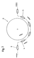
- the foil bags are left after leaving the tubular bag machine 13, e.g. fed by a conveyor belt, a test carousel 29.
- a test carousel 29 This is a (continuously) rotating conveyor with receptacles or pockets on the circumference.
- Each bag holds a foil bag 10.
- each pocket is equipped with the test organs and clamping elements in order to carry out the test during the transport of the film bags 10.
- the film bags 10 are conveyed along a semicircle by the test carousel 29 and then transferred to a conveyor to the packaging station. In the area of the test carousel 29, the film bags 10 are also in an upright position.
- test method is expediently carried out over a longer period of time, in the embodiment according to FIG. 7 in the area of the test carousel 29.
- the test organs (test plunger 18) thereby come during a long-term effect. This makes it possible to check bags with small leaks.
Landscapes
- Physics & Mathematics (AREA)
- General Physics & Mathematics (AREA)
- Examining Or Testing Airtightness (AREA)
- Containers And Plastic Fillers For Packaging (AREA)
Applications Claiming Priority (2)
| Application Number | Priority Date | Filing Date | Title |
|---|---|---|---|
| DE4223793A DE4223793A1 (de) | 1992-07-20 | 1992-07-20 | Verfahren und Vorrichtung zum Prüfen der Dichtigkeit von Folienbeuteln |
| DE4223793 | 1992-07-20 |
Publications (3)
| Publication Number | Publication Date |
|---|---|
| EP0580063A2 true EP0580063A2 (fr) | 1994-01-26 |
| EP0580063A3 EP0580063A3 (en) | 1994-07-06 |
| EP0580063B1 EP0580063B1 (fr) | 1997-06-04 |
Family
ID=6463612
Family Applications (1)
| Application Number | Title | Priority Date | Filing Date |
|---|---|---|---|
| EP93111176A Expired - Lifetime EP0580063B1 (fr) | 1992-07-20 | 1993-07-13 | Méthode et dispositif pour tester l'étanchéité des sachets en feuille |
Country Status (5)
| Country | Link |
|---|---|
| US (1) | US5507177A (fr) |
| EP (1) | EP0580063B1 (fr) |
| JP (1) | JPH06171622A (fr) |
| BR (1) | BR9302912A (fr) |
| DE (2) | DE4223793A1 (fr) |
Cited By (3)
| Publication number | Priority date | Publication date | Assignee | Title |
|---|---|---|---|---|
| DE19648778A1 (de) * | 1996-11-25 | 1998-05-28 | Kronseder Maschf Krones | Verfahren und Vorrichtung zur Leckage- und Dichtigkeitsprüfung von gefüllten und verschlossenen Flaschen oder dergleichen |
| DE19714314C1 (de) * | 1997-04-08 | 1998-05-28 | Kali & Salz Beteiligungs Ag | Verfahren und Einrichtung zur Überprüfung der Ventildichtheit gefüllter Ventilsäcke |
| DE19703528B4 (de) * | 1996-11-25 | 2008-12-24 | Krones Ag | Verfahren und Vorrichtung zur Dichtigkeitsprüfung von verschlossenen Flaschen o. dgl. |
Families Citing this family (15)
| Publication number | Priority date | Publication date | Assignee | Title |
|---|---|---|---|---|
| DE19524844A1 (de) * | 1995-07-07 | 1997-01-09 | Heuft Systemtechnik Gmbh | Verfahren und Vorrichtung zum Prüfen von verformbaren Behältern auf Dichtigkeit |
| US5773711A (en) * | 1996-01-09 | 1998-06-30 | Mitsubishi Materials Corporation | Can internal pressure inspection apparatus |
| EP1086897B1 (fr) * | 1999-09-27 | 2008-10-29 | Ishida Co., Ltd. | Machine d'inspection du scellage pour des produits ensachés |
| WO2001029528A2 (fr) * | 1999-10-19 | 2001-04-26 | Benthos, Inc. | Inspection de recipient sur une chaine de fabrication au moyen de plusieurs capteurs |
| US6415651B1 (en) * | 2000-06-23 | 2002-07-09 | The Quaker Oats Company | Mobile pneumatic apparatus and method for testing a container seal |
| US7204956B1 (en) * | 2003-03-11 | 2007-04-17 | Prontex Investments Llp, Societe De Droit Anglais | Method for controlling the operation of a heat-disinfecting device for waste, viz. biologically hazardous waste |
| JP4699188B2 (ja) * | 2005-11-30 | 2011-06-08 | 株式会社イシダ | シールチェック装置 |
| JP4927399B2 (ja) * | 2005-12-22 | 2012-05-09 | 株式会社イシダ | シールチェック装置 |
| DE102007029278A1 (de) * | 2007-06-22 | 2008-12-24 | Haver & Boecker Ohg | Packmaschine und Austrageeinrichtung für eine Packmaschine |
| US8578760B2 (en) * | 2009-09-08 | 2013-11-12 | Industrial Dynamics Company, Ltd | Container inspection utilizing linear force actuator |
| RU2544263C2 (ru) * | 2009-12-29 | 2015-03-20 | Нестек С.А. | Устройство для определения целостности герметизации контейнера и способ его применения |
| DE102013002856A1 (de) | 2013-02-20 | 2014-08-21 | Iwk Verpackungstechnik Gmbh | Verfahren und Vorrichtung zur Dichtigkeitskontrolle eines Behältnisses |
| JP6084110B2 (ja) * | 2013-05-02 | 2017-02-22 | 東洋自動機株式会社 | エアバッグ付き袋のエアバッグ部の気体圧力検査装置 |
| AU2019202889B2 (en) * | 2018-04-30 | 2024-10-10 | Tna Australia Pty Limited | A bag engaging device |
| US11801533B1 (en) | 2021-12-31 | 2023-10-31 | Aaron Thomas Bacon | Automated sorting of sealable bags |
Family Cites Families (13)
| Publication number | Priority date | Publication date | Assignee | Title |
|---|---|---|---|---|
| US3918293A (en) * | 1973-03-19 | 1975-11-11 | Neo Dyne Ind Inc | Apparatus for testing and emplacing flexible sealed packages |
| US4024956A (en) * | 1975-11-20 | 1977-05-24 | American Brands, Inc. | Method and apparatus for detecting leaks |
| NL7810210A (nl) * | 1978-10-10 | 1980-04-14 | D E J Int Research | Apparaat en werkwijze voor het meten van de druk in vacuumdichte houders, gebruikt als verpakking. |
| US4510730A (en) * | 1981-12-18 | 1985-04-16 | Hulbritt Developments Limited | Apparatus for seal-testing sachets, packets and the like |
| US4517827A (en) * | 1983-03-24 | 1985-05-21 | General Foods Incorporated | Apparatus and method for testing for leakages in hermetically-sealed packages |
| GB2162648A (en) * | 1984-08-04 | 1986-02-05 | Hulbritt Packaging Systems Lim | Bag testing |
| US4955226A (en) * | 1984-12-26 | 1990-09-11 | Frito-Lay, Inc. | Method and apparatus for automatically detecting the presence of holes in filled and sealed packed plastic bags |
| GB2196130A (en) * | 1986-08-22 | 1988-04-20 | Jeyes Group Ltd | Method and apparatus for testing filled containers for leakage |
| DE3716095C1 (de) * | 1987-05-14 | 1988-09-08 | Hamba Maschf | Becherfuellwerk fuer Nahrungs- und Genussmittel,insbesondere fuer Molkereiprodukte |
| DD273409C2 (de) * | 1988-06-27 | 1990-10-24 | Konsum Rationalisierungszentru | Anordnung zur dichtheitskontrolle von forminstabilen beutelpackungen |
| JPH0238835A (ja) * | 1988-07-28 | 1990-02-08 | Hihakai Kensa Kk | 包装体の気密漏洩検査方法およびそれに用いる気密漏洩検査装置 |
| JPH0314435A (ja) * | 1989-06-01 | 1991-01-23 | Tokihisa Masuda | シールチェックの装置及び方法 |
| GB9204137D0 (en) * | 1992-02-26 | 1992-04-08 | Fenlon Christopher | Sealed package integrity testing machine |
-
1992
- 1992-07-20 DE DE4223793A patent/DE4223793A1/de not_active Withdrawn
-
1993
- 1993-07-13 DE DE59306639T patent/DE59306639D1/de not_active Expired - Fee Related
- 1993-07-13 EP EP93111176A patent/EP0580063B1/fr not_active Expired - Lifetime
- 1993-07-19 BR BR9302912A patent/BR9302912A/pt not_active IP Right Cessation
- 1993-07-20 JP JP5179378A patent/JPH06171622A/ja active Pending
-
1994
- 1994-12-22 US US08/361,711 patent/US5507177A/en not_active Expired - Fee Related
Cited By (4)
| Publication number | Priority date | Publication date | Assignee | Title |
|---|---|---|---|---|
| DE19648778A1 (de) * | 1996-11-25 | 1998-05-28 | Kronseder Maschf Krones | Verfahren und Vorrichtung zur Leckage- und Dichtigkeitsprüfung von gefüllten und verschlossenen Flaschen oder dergleichen |
| DE19648778C2 (de) * | 1996-11-25 | 2001-07-05 | Krones Ag | Verfahren und Vorrichtung zur Leckage- und Dichtigkeitsprüfung von gefüllten und verschlossenen Flaschen oder dergleichen |
| DE19703528B4 (de) * | 1996-11-25 | 2008-12-24 | Krones Ag | Verfahren und Vorrichtung zur Dichtigkeitsprüfung von verschlossenen Flaschen o. dgl. |
| DE19714314C1 (de) * | 1997-04-08 | 1998-05-28 | Kali & Salz Beteiligungs Ag | Verfahren und Einrichtung zur Überprüfung der Ventildichtheit gefüllter Ventilsäcke |
Also Published As
| Publication number | Publication date |
|---|---|
| JPH06171622A (ja) | 1994-06-21 |
| BR9302912A (pt) | 1994-02-22 |
| DE59306639D1 (de) | 1997-07-10 |
| EP0580063B1 (fr) | 1997-06-04 |
| EP0580063A3 (en) | 1994-07-06 |
| DE4223793A1 (de) | 1994-01-27 |
| US5507177A (en) | 1996-04-16 |
Similar Documents
| Publication | Publication Date | Title |
|---|---|---|
| EP0580063B1 (fr) | Méthode et dispositif pour tester l'étanchéité des sachets en feuille | |
| US4955226A (en) | Method and apparatus for automatically detecting the presence of holes in filled and sealed packed plastic bags | |
| DE69303010T2 (de) | Prüfung von verpackungen | |
| EP0562349B2 (fr) | Procédé et appareil pour sortir des emballages défectueux d'une machine d'emballage | |
| DE60001684T2 (de) | System zum automatischen Prüfen von Verpackungen | |
| EP0833133A2 (fr) | Moyens de raccordement pour les appareils pour la détermination de la capacité des récipients | |
| DE102007029278A1 (de) | Packmaschine und Austrageeinrichtung für eine Packmaschine | |
| DE1934798A1 (de) | Verfahren und Vorrichtung zum Verpacken von Gegenstaenden und zum Pruefen dieser Verpackungen auf Dichtheit | |
| EP0459335A2 (fr) | Utilisation d'un procédé et dispositif pour l'examen de fuite | |
| DE69201458T2 (de) | Verfahren und Vorrichtung zur Prüfung der Dichtung einer gefüllten und geschlossenen flexiblen Verpackung. | |
| DE19813215A1 (de) | Schlauchbeutelmaschine | |
| DE3936163C2 (fr) | ||
| DE68904097T2 (de) | Verfahren zur dichtigkeitspruefung einer verpackung. | |
| DE10102820A1 (de) | Verfahren zur Herstellung einer Blisterverpackung und Blisterverpackungsmaschine | |
| AT14364U1 (de) | Verfahren und Vorrichtung zum Messen des Gasgehalts von in Kunststofffolien, Glas oder anderen lichtdurchlässigen Materialien verpackten gegenüber einem zu messenden Gas empfindlichen Materialien | |
| DE2345016A1 (de) | Verfahren und vorrichtung zur dichtheitspruefung von plastischen fluessigkeitsbehaeltern | |
| DE10001300A1 (de) | Dichtheitsprüfung nach dem Unterdruckverfahren | |
| DE102008047820A1 (de) | Verfahren und Vorrichtung zur Undichtigkeitsprüfung von mit Schüttgut gefüllten Säcken und Transporteinrichtung | |
| DE3725739C2 (de) | Verfahren zum Überprüfen der Dichtheit von mit aufgeschweißtem Deckel versehenen Kunststoffbechern | |
| DE102020134190B4 (de) | Verfahren zum Betrieb einer Schlauchbeutelmaschine | |
| DE19714314C1 (de) | Verfahren und Einrichtung zur Überprüfung der Ventildichtheit gefüllter Ventilsäcke | |
| DE3801651C2 (fr) | ||
| DE3916566A1 (de) | Verfahren und vorrichtung zur pruefung der dichtigkeit von gefuellten behaeltern | |
| DE102024128993A1 (de) | Verfahren und Vorrichtung zur Prüfung der Dichtigkeit einer verschlossenen Packung | |
| DE3135885A1 (de) | Sackfuellvorrichtung fuer staubige gueter |
Legal Events
| Date | Code | Title | Description |
|---|---|---|---|
| PUAI | Public reference made under article 153(3) epc to a published international application that has entered the european phase |
Free format text: ORIGINAL CODE: 0009012 |
|
| AK | Designated contracting states |
Kind code of ref document: A2 Designated state(s): DE FR GB IT |
|
| PUAL | Search report despatched |
Free format text: ORIGINAL CODE: 0009013 |
|
| AK | Designated contracting states |
Kind code of ref document: A3 Designated state(s): DE FR GB IT |
|
| 17P | Request for examination filed |
Effective date: 19940629 |
|
| 17Q | First examination report despatched |
Effective date: 19960213 |
|
| GRAG | Despatch of communication of intention to grant |
Free format text: ORIGINAL CODE: EPIDOS AGRA |
|
| GRAH | Despatch of communication of intention to grant a patent |
Free format text: ORIGINAL CODE: EPIDOS IGRA |
|
| GRAH | Despatch of communication of intention to grant a patent |
Free format text: ORIGINAL CODE: EPIDOS IGRA |
|
| GRAA | (expected) grant |
Free format text: ORIGINAL CODE: 0009210 |
|
| AK | Designated contracting states |
Kind code of ref document: B1 Designated state(s): DE FR GB IT |
|
| GBT | Gb: translation of ep patent filed (gb section 77(6)(a)/1977) |
Effective date: 19970606 |
|
| REF | Corresponds to: |
Ref document number: 59306639 Country of ref document: DE Date of ref document: 19970710 |
|
| ET | Fr: translation filed | ||
| PLBE | No opposition filed within time limit |
Free format text: ORIGINAL CODE: 0009261 |
|
| STAA | Information on the status of an ep patent application or granted ep patent |
Free format text: STATUS: NO OPPOSITION FILED WITHIN TIME LIMIT |
|
| 26N | No opposition filed | ||
| REG | Reference to a national code |
Ref country code: GB Ref legal event code: IF02 |
|
| PGFP | Annual fee paid to national office [announced via postgrant information from national office to epo] |
Ref country code: GB Payment date: 20040707 Year of fee payment: 12 |
|
| PGFP | Annual fee paid to national office [announced via postgrant information from national office to epo] |
Ref country code: FR Payment date: 20040708 Year of fee payment: 12 |
|
| PG25 | Lapsed in a contracting state [announced via postgrant information from national office to epo] |
Ref country code: IT Free format text: LAPSE BECAUSE OF NON-PAYMENT OF DUE FEES;WARNING: LAPSES OF ITALIAN PATENTS WITH EFFECTIVE DATE BEFORE 2007 MAY HAVE OCCURRED AT ANY TIME BEFORE 2007. THE CORRECT EFFECTIVE DATE MAY BE DIFFERENT FROM THE ONE RECORDED. Effective date: 20050713 Ref country code: GB Free format text: LAPSE BECAUSE OF NON-PAYMENT OF DUE FEES Effective date: 20050713 |
|
| GBPC | Gb: european patent ceased through non-payment of renewal fee |
Effective date: 20050713 |
|
| PG25 | Lapsed in a contracting state [announced via postgrant information from national office to epo] |
Ref country code: FR Free format text: LAPSE BECAUSE OF NON-PAYMENT OF DUE FEES Effective date: 20060331 |
|
| REG | Reference to a national code |
Ref country code: FR Ref legal event code: ST Effective date: 20060331 |
|
| PGFP | Annual fee paid to national office [announced via postgrant information from national office to epo] |
Ref country code: DE Payment date: 20060714 Year of fee payment: 14 |
|
| PG25 | Lapsed in a contracting state [announced via postgrant information from national office to epo] |
Ref country code: DE Free format text: LAPSE BECAUSE OF NON-PAYMENT OF DUE FEES Effective date: 20080201 |