EP0580154B1 - Procédé pour former des gouttelettes d'encre dans une imprimante du type à jet d'encre et appareil d'enregistrement de ce type - Google Patents
Procédé pour former des gouttelettes d'encre dans une imprimante du type à jet d'encre et appareil d'enregistrement de ce type Download PDFInfo
- Publication number
- EP0580154B1 EP0580154B1 EP93111710A EP93111710A EP0580154B1 EP 0580154 B1 EP0580154 B1 EP 0580154B1 EP 93111710 A EP93111710 A EP 93111710A EP 93111710 A EP93111710 A EP 93111710A EP 0580154 B1 EP0580154 B1 EP 0580154B1
- Authority
- EP
- European Patent Office
- Prior art keywords
- ink
- pressure generation
- generation chamber
- speed
- jet type
- Prior art date
- Legal status (The legal status is an assumption and is not a legal conclusion. Google has not performed a legal analysis and makes no representation as to the accuracy of the status listed.)
- Expired - Lifetime
Links
- 238000000034 method Methods 0.000 title claims description 27
- 239000003990 capacitor Substances 0.000 claims description 22
- 230000007274 generation of a signal involved in cell-cell signaling Effects 0.000 description 9
- 230000008602 contraction Effects 0.000 description 8
- 239000007788 liquid Substances 0.000 description 4
- 230000003247 decreasing effect Effects 0.000 description 3
- 238000010586 diagram Methods 0.000 description 3
- 230000035939 shock Effects 0.000 description 3
- 238000006073 displacement reaction Methods 0.000 description 2
- 230000020169 heat generation Effects 0.000 description 2
- 238000007641 inkjet printing Methods 0.000 description 2
- 239000000463 material Substances 0.000 description 2
- 238000007639 printing Methods 0.000 description 2
- 238000004088 simulation Methods 0.000 description 2
- 125000006850 spacer group Chemical group 0.000 description 2
- XLYOFNOQVPJJNP-UHFFFAOYSA-N water Substances O XLYOFNOQVPJJNP-UHFFFAOYSA-N 0.000 description 2
- 239000002131 composite material Substances 0.000 description 1
- 238000007796 conventional method Methods 0.000 description 1
- 230000001419 dependent effect Effects 0.000 description 1
- 238000007599 discharging Methods 0.000 description 1
- 238000001035 drying Methods 0.000 description 1
- 230000000694 effects Effects 0.000 description 1
- 238000010438 heat treatment Methods 0.000 description 1
- 230000005499 meniscus Effects 0.000 description 1
- 238000011017 operating method Methods 0.000 description 1
- 230000000644 propagated effect Effects 0.000 description 1
- 230000000630 rising effect Effects 0.000 description 1
- 238000007493 shaping process Methods 0.000 description 1
- 239000002904 solvent Substances 0.000 description 1
Images


Classifications
-
- B—PERFORMING OPERATIONS; TRANSPORTING
- B41—PRINTING; LINING MACHINES; TYPEWRITERS; STAMPS
- B41J—TYPEWRITERS; SELECTIVE PRINTING MECHANISMS, i.e. MECHANISMS PRINTING OTHERWISE THAN FROM A FORME; CORRECTION OF TYPOGRAPHICAL ERRORS
- B41J2/00—Typewriters or selective printing mechanisms characterised by the printing or marking process for which they are designed
- B41J2/005—Typewriters or selective printing mechanisms characterised by the printing or marking process for which they are designed characterised by bringing liquid or particles selectively into contact with a printing material
- B41J2/01—Ink jet
- B41J2/015—Ink jet characterised by the jet generation process
- B41J2/04—Ink jet characterised by the jet generation process generating single droplets or particles on demand
- B41J2/045—Ink jet characterised by the jet generation process generating single droplets or particles on demand by pressure, e.g. electromechanical transducers
- B41J2/04501—Control methods or devices therefor, e.g. driver circuits, control circuits
- B41J2/04516—Control methods or devices therefor, e.g. driver circuits, control circuits preventing formation of satellite drops
-
- B—PERFORMING OPERATIONS; TRANSPORTING
- B41—PRINTING; LINING MACHINES; TYPEWRITERS; STAMPS
- B41J—TYPEWRITERS; SELECTIVE PRINTING MECHANISMS, i.e. MECHANISMS PRINTING OTHERWISE THAN FROM A FORME; CORRECTION OF TYPOGRAPHICAL ERRORS
- B41J2/00—Typewriters or selective printing mechanisms characterised by the printing or marking process for which they are designed
- B41J2/005—Typewriters or selective printing mechanisms characterised by the printing or marking process for which they are designed characterised by bringing liquid or particles selectively into contact with a printing material
- B41J2/01—Ink jet
- B41J2/015—Ink jet characterised by the jet generation process
- B41J2/04—Ink jet characterised by the jet generation process generating single droplets or particles on demand
- B41J2/045—Ink jet characterised by the jet generation process generating single droplets or particles on demand by pressure, e.g. electromechanical transducers
- B41J2/04501—Control methods or devices therefor, e.g. driver circuits, control circuits
- B41J2/04541—Specific driving circuit
-
- B—PERFORMING OPERATIONS; TRANSPORTING
- B41—PRINTING; LINING MACHINES; TYPEWRITERS; STAMPS
- B41J—TYPEWRITERS; SELECTIVE PRINTING MECHANISMS, i.e. MECHANISMS PRINTING OTHERWISE THAN FROM A FORME; CORRECTION OF TYPOGRAPHICAL ERRORS
- B41J2/00—Typewriters or selective printing mechanisms characterised by the printing or marking process for which they are designed
- B41J2/005—Typewriters or selective printing mechanisms characterised by the printing or marking process for which they are designed characterised by bringing liquid or particles selectively into contact with a printing material
- B41J2/01—Ink jet
- B41J2/015—Ink jet characterised by the jet generation process
- B41J2/04—Ink jet characterised by the jet generation process generating single droplets or particles on demand
- B41J2/045—Ink jet characterised by the jet generation process generating single droplets or particles on demand by pressure, e.g. electromechanical transducers
- B41J2/04501—Control methods or devices therefor, e.g. driver circuits, control circuits
- B41J2/04581—Control methods or devices therefor, e.g. driver circuits, control circuits controlling heads based on piezoelectric elements
-
- B—PERFORMING OPERATIONS; TRANSPORTING
- B41—PRINTING; LINING MACHINES; TYPEWRITERS; STAMPS
- B41J—TYPEWRITERS; SELECTIVE PRINTING MECHANISMS, i.e. MECHANISMS PRINTING OTHERWISE THAN FROM A FORME; CORRECTION OF TYPOGRAPHICAL ERRORS
- B41J2/00—Typewriters or selective printing mechanisms characterised by the printing or marking process for which they are designed
- B41J2/005—Typewriters or selective printing mechanisms characterised by the printing or marking process for which they are designed characterised by bringing liquid or particles selectively into contact with a printing material
- B41J2/01—Ink jet
- B41J2/015—Ink jet characterised by the jet generation process
- B41J2/04—Ink jet characterised by the jet generation process generating single droplets or particles on demand
- B41J2/045—Ink jet characterised by the jet generation process generating single droplets or particles on demand by pressure, e.g. electromechanical transducers
- B41J2/04501—Control methods or devices therefor, e.g. driver circuits, control circuits
- B41J2/04588—Control methods or devices therefor, e.g. driver circuits, control circuits using a specific waveform
-
- B—PERFORMING OPERATIONS; TRANSPORTING
- B41—PRINTING; LINING MACHINES; TYPEWRITERS; STAMPS
- B41J—TYPEWRITERS; SELECTIVE PRINTING MECHANISMS, i.e. MECHANISMS PRINTING OTHERWISE THAN FROM A FORME; CORRECTION OF TYPOGRAPHICAL ERRORS
- B41J2/00—Typewriters or selective printing mechanisms characterised by the printing or marking process for which they are designed
- B41J2/005—Typewriters or selective printing mechanisms characterised by the printing or marking process for which they are designed characterised by bringing liquid or particles selectively into contact with a printing material
- B41J2/01—Ink jet
- B41J2/135—Nozzles
- B41J2/14—Structure thereof only for on-demand ink jet heads
- B41J2002/14387—Front shooter
Definitions
- the present invention relates to method for forming ink droplets in ink-jet type printer and ink-jet type recording device.
- a conventional on-demand type of ink-jet recording device has a recording head which includes a plurality of pressure generation chambers for generating an ink pressure by means of piezoelectric vibrators or heating elements, a common reservoir for supplying ink to the respective pressure generation chambers, and nozzle openings communicating with the respective pressure generation chambers.
- a drive signal is applied to the pressure generation chambers corresponding to a print signal to thereby jet out ink droplets from the nozzle openings onto a recording medium.
- Such an ink-jet recording head can be classified into two types: one a bubble-jet type in which a resistance wire, as pressure generation means, generates Joule heat in a pressure generation chamber responsive to a drive signal, and the other a piezoelectric vibration type in which part of a pressure generation chamber is formed by a diaphragm and the diaphragm is compressed and shifted by means of a piezoelectric vibrator.
- the former type utilizes the vapor pressure of the ink solvent vaporized instantaneously due to the heat generation of the resistance wire, only a small quantity of ink in the form of droplets can be jetted out, which makes it possible to realize printing at a high resolution as well as quick drying of the ink droplets.
- the heat generation of the resistance wire can cause the ink and recording head to deteriorate in quality readily.
- the recording head can enjoy a semi-permanent life, and operating costs are low.
- the quantity of the ink droplets is great and the time necessary to dry the ink droplets is long.
- the ink is caused to fly in a column-like stream (similar to water shot from a water pistol), so that there is a time difference or a speed difference between the leading and trailing end portions of the flying ink, with the result that unwanted small ink droplets are generated, causing the printed dot to be distorted.
- the generation of the small ink droplets incidental to the tail end of the ink column is prevented, that is, the generation of so-called "satellite” ink droplets is prevented, so that the printed dots can be made circular.
- Prior art document EP-A-0 194 852 describes an operating method of an ink jet apparatus wherein an ink jet head is driven by a composite waveform which includes independent and successive first, second and third electrical pulses, each having an exponential leading edge and a step-like trailing edge. These pulses are separated from each other by specific periods.
- the present invention is directed towards eliminating the problems in the above-mentioned conventional ink-jet recording devices.
- the invention therefore provides an ink droplet forming method according to independent claim 1 and an ink jet type recording device according to independent claim 5. Further advantageous features aspects and details of the invention are evident from the dependent claims the description and the drawings.
- the invention provides on-demand type ink-jet recording device and, in particular, a technique for driving a recording head of an on-demand type ink-jet recording device.
- the on-demand type ink-jet recording device does not apply an unreasonably high force to a piezoelectric vibrator and a pressure generation chamber forming member, and/or can reduce the length of ink droplets jetted from the nozzle openings, that is, the length extending from the leading end to the trailing end thereof, or a time difference between the passing of the leading and trailing ends of the ink droplets , to thereby form spherical droplets and circular dots on the printed page.
- a method for driving an ink-jet recording head including flow path forming means having a nozzle opening and adapted to be able to vary the volume of a pressure generation chamber by means of a piezoelectric vibrator when the chamber receives ink supplied from an ink reservoir, the method comprising a first step of expanding the pressure generation chamber to thereby suck in ink, a second step of contracting the pressure generation chamber at a first speed, and a third step of contracting the pressure generation chamber at a second speed switched from the first speed, the first speed being set smaller than the second speed.
- the contracting speed of the pressure generation chamber is increased to thereby enhance the ink jetting speed.
- ink can be jetted out continuously in such a manner that the ink follows and catches up with the leading end of the ink jetted out previously. For this reason, the speed difference between the leading and trailing ends of the ink column is decreased to thereby allow a spherical ink droplet to reach the recording paper.
- a time difference between the leading and trailing ends of an ink column jetted out from a nozzle opening is reduced without decreasing the average speed of the ink column so as to prevent generation of satellites droplets and the like.
- a capacitor maintaining a voltage for expansion of a pressure generation chamber is discharged by switching a plurality of resistances differing in the discharge resistance thereof by means of switching transistors.
- the terminal voltage of the capacitor is caused to vary at a speed which is determined by the values of the resistances. Therefore, by selecting the values of the resistances such that the absolute value of the differential value of the terminal voltage increases with time, the rate of contraction of the pressure generation chamber can be increased gradually to thereby minimize a speed difference between the leading and trailing ends of the ink column.
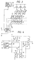
- FIG. 1 there is shown an embodiment of an ink-jet recording head which is driven by a head drive circuit according to the invention.
- reference numeral 1 designates a pressure generation chamber formed by a nozzle plate 3 having a nozzle opening 2 therein, a vibration plate 4 in contact with the leading end of a piezoelectric vibrator (described below), and a spacer 5 held between the nozzle plate 3 and vibration plate 4.
- the pressure generation chamber 1 receives ink through an ink supply port 6 from a reservoir 14 which is connected to an ink tank (not shown).
- Reference numeral 7 designates the above-mentioned piezoelectric vibrator.
- the vibrator 7 is constructed in a laminated structure in which a piezoelectric material 8 and electrode-forming materials 9 and 10 are arranged in a sandwiched manner.
- the vibrator 7 further includes an inactive area which does not contribute to vibration and is fixed to a fixing base plate 11.
- the fixing base plate 11, vibration plate 3, spacer 5 and vibration plate 4 are fixed together integrally through a base member 12 to thereby form an ink-jet recording head.
- the piezoelectric vibrator 7 when a voltage is applied to the electrodes 9 and 10 of the piezoelectric vibrator 7, the piezoelectric vibrator 7 is caused to extend toward the nozzle plate 3 to displace the vibration plate 4, so that the volume of the pressure generation chamber 1 is reduced.
- a bias voltage of 30 V is previously applied to the piezoelectric vibrator 7 and, from this state, if the bias voltage is decreased to 0 V, then the piezoelectric vibrator 7 is caused to contract. This draws the meniscus of the nozzle opening toward the pressure generation chamber 1 and, at the same time, the ink in the reservoir 14 is allowed to flow through the ink supply port into the pressure generation chamber 1.
- the piezoelectric vibrator 7 is expanded to thereby cause the vibration plate 4 to compress the pressure generation chamber 1.
- the ink in the pressure generation chamber 1 is pushed out into the nozzle opening 2 and ink supply port 6. That is, the leading end portion a of the ink is projected out from the nozzle opening 2 (Fig. 2(I)), then it follows the displacement of the vibration plate 4 and is jetted out in the form of a liquid column (Fig. 2(II)).
- the liquid column is broken off after expansion of the piezoelectric vibrator 7 is stopped.
- the trailing end portion c of the liquid column is discharged from the nozzle opening 2 in a such manner to chase the leading end portion a (Fig. 2(III)).
- the liquid column flies toward the recording paper at the speed of expansion of the piezoelectric vibrator 7, that is, at a speed proportional to the rate of contraction of the pressure generation chamber 1, forming a dot on the recording paper.
- FIG. 3 there is shown an embodiment of a drive circuit which is used to drive the above-mentioned recording head.
- reference numeral 20 designates a print control circuit.
- a timing signal from an external device is input to a terminal 21 of the print control circuit 20, and a print signal from an external device is input to a terminal 22.
- the print control circuit 20 outputs a latch signal from a terminal 23, a print signal from a terminal 24, and a shift clock signal from a terminal 25.
- the print signal from the terminal 24 is shifted by the shift clock signal from the terminal 25 through flip-flop circuits 26 sequentially, and also is temporarily stored and held by the latch signal from the terminal 23 in flip-flop circuits 27.
- Reference numeral 30 designates a drive signal generation circuit which generates a drive signal identical to the timing signal input to the terminal 21 from the external device and outputs the drive signal to the one-side electrodes of respectively connected piezoelectric vibrators 7 in parallel to a terminal 31.
- reference numerals 29 designate switching transistors which are connected between the other-side electrodes of the piezoelectric vibrators 7 and ground.
- the switching transistors 29 are turned on responsive to signals from the flip-flop circuits 27, and apply the drive signal from the drive signal generation circuit 30 to the selected piezoelectric vibrators 7.
- Fig. 4 there is shown an embodiment of the above-mentioned drive signal generation circuit 30, in which, when the timing signal is input to the terminal 21, a transistor 40 is turned on and, in cooperation with a transistor 41 which is paired with the transistor 40 to form a current mirror circuit, the transistor 40 charges a capacitor 43 with a given current whose magnitude is determined by a resistance 42.
- the terminal voltage of the capacitor 43 generated in this charging process is amplified by a circuit composed of the transistors 44 and 45 and is then applied to the terminal 31.
- the transistor 40 After a given time has passed and thus the timing signal rises, the transistor 40 is turned off and, at the same time, a one-shot multivibrator 47 is operated at the rising edge of the timing signal. This causes a transistor 48 to turn on and, therefore, transistors 49 and 50 are also turned on, so that the capacitor 43 is discharged with a given current whose magnitude is determined by a resistance 51. The terminal voltage of the capacitor 43 resulting from this discharge is amplified by the two transistors 44 and 45, and it is then output to the terminal 31.
- the transistor 48 is turned off, and at the same time a one-shot multivibrator 53 is operated and a transistor 54 is turned on. This causes transistors 55 and 56 to turn on.
- the capacitor 43 continues to discharge with a given current determined by a resistance 57.
- the terminal voltage of the capacitor 43 which varies according to the resistance 57, is amplified by the transistors 44 and 45 and then output to the terminal 31.
- the absolute values of the differential coefficients of the voltage signals V1 and V2 applied to expand the piezoelectric vibrator 7 are caused to vary with time.
- the piezoelectric vibrator 7 is expanded, its expansion speed is increased from S1 to S2, and thus the displacement speed of the vibration plate 4, which is mounted on the piezoelectric vibrator 7, is also increased.
- the ink pressure generated in the pressure generation chamber 1 is also increased so that the speed of the ink column is increased as time passes when the ink column is ejected from the nozzle opening 2.
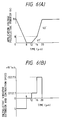
- Figs. 6(A) and 6(B) show the relation between the changes with time of the application voltage of the piezoelectric vibrator in an actual device constructed according to the above-described embodiment of the inventive drive device and the expansion and contraction speed of the piezoelectric vibrator due to the application voltage, that is, the volumetric speed of the pressure generation chamber.
- a signal V1' having a given gradient just before the jetting out of the ink droplets is applied for a period of time of 4 ⁇ s, and then a signal V2' having a larger gradient than the given gradient is applied.
- a speed S1 for example, 2.7 ⁇ 10 -2 m/s
- S2 for example, 7.3 ⁇ 10 -2 m/s
- the speed of the leading end of the ink droplet is smaller while the speed of the trailing end thereof is greater than the leading end speed, so that the difference between the speeds of the leading and trailing ends of the ink droplet can be reduced by one-half or less.
- the leading end has reached only a distance of the order of 500 ⁇ m from the nozzle opening (see Fig. 7 (VIII)).
- the leading end thereof has flown 500 ⁇ m or more, that is, as can be clearly seen from Fig. 8 (VII), it has flown outside of the view of Fig. 8.
- the shock acting on the piezoelectric vibrator and vibration plate at the time of jetting out of the ink droplet can be made smaller. This reduces the fatigue of the vibration plate and piezoelectric vibrator and also reduces the shocks that are propagated to other adjoining pressure generation chambers thereby to reduce crosstalk.
- the timing signal for generation of the drive signal is produced by the drive signal generation circuit.
- the timing signal may be generated by the control signal generation circuit. In this case as well, it is clear that a similar action can be provided.
- two gradients are employed for the drive signal to be applied when the piezoelectric vibrator is expanded.
- three signals V1', V2' and V3' differing in the absolute values of the differential coefficients thereof from each other are applied to the piezoelectric vibrator so that the piezoelectric vibrator is expanded at speeds S1, S2 and S3 which increase gradually.
- the speeds of the leading end, central portion and trailing end of the ink column can be made to approach further to each other so as to more surely prevent generation of so-called "satellite” ink droplets, that is, unwanted very fine ink droplets.
- a piezoelectric vibrator which expands when a voltage is applied thereto.
- a similar effect can be obtained in the case of an ink-jet recording head of a type that a piezoelectric vibrator is contracted to thereby expand a pressure chamber when a drive signal as shown in Figs. 11(A) and 11(B) is applied to the piezoelectric vibrator.
- a drive signal generation circuit suitable for the latter type of recording head.
- a timing signal is input to a terminal 60 (Fig. 13, T0)
- a transistor 61 is turned on to thereby turn on a transistor 62.
- the transistor 62 in cooperation with a transistor 63 which is paired with the transistor 62 to form a current mirror circuit, charges a capacitor 65 with a given current whose magnitude is determined by a resistance 64.
- the terminal voltage of the capacitor 65 produced in this charging process is amplified by a circuit comprising transistors 66 and 67, and is then output to the terminal 31 as a signal V1.
- the piezoelectric vibrator expands according to a differential value determined by the value of a resistance 64, thereby generating an ink droplet.
- the transistor 61 Since the timing signal falls at a time T1 after a given time has elapsed, the transistor 61 is turned off, while there is output a pulse signal from a one-shot multivibrator 70 to thereby turn on a transistor 71.
- a transistor 73 which is paired with the transistor 71 in a current mirror circuit, is turned on and thus continues to charge the capacitor 65 with a given current determined by the value of the resistance 74.
- the terminal voltage of the capacitor 65 is amplified by the transistors 66 and 67, and is then output to the terminal 31 as a signal V2, with the result that the piezoelectric vibrator 7 expands up to a time T2 according to a differential value determined by the resistance 74.
- the signal is set by selecting the value of the resistance 74 such that the absolute value of the differential value is greater than that of the signal V1 just before the signal V2. That is, as described before, the signal V2 allows generation of an ink column including a portion having a higher speed than that of the leading end of an ink column generated by the signal V1.
- an ink droplet forming method which comprises a step of contracting the pressure generation chamber at a first speed and a step of contracting the pressure generation chamber at a second speed different from the first speed, wherein the second speed is greater than the first speed. Accordingly, it is possible to minimize as much as possible the length of the ink column jetted from the nozzle opening, that is, the length extending from the leading end of the droplet to the trailing end thereof, to thereby form a spherical ink droplet. This makes it possible to prevent generation of a satellite ink droplets and thus improves printing quality.
- the vibration plate and piezoelectric vibrator since it is possible to minimize the first voltage which is applied to compress the pressure generation chamber in order to generate an ink droplet, it is possible to reduce the amount of shock acting on the vibration plate and piezoelectric vibrator at the beginning of the jetting-out of the ink droplets, which in turn makes it possible to reduce the fatigue of the vibration plate and piezoelectric vibrator as well as to minimize crosstalk.
Landscapes
- Particle Formation And Scattering Control In Inkjet Printers (AREA)
- Ink Jet (AREA)
Claims (8)
- Procédé de formation de gouttelettes d'encre pour le pilotage d'une tête d'enregistrement du type à jets d'encre qui comporte un organe (3) de formation d'un passage de circulation possédant une ouverture (2) de buse, une chambre génératrice de pression (1) qui reçoit de l'encre et un vibrateur piézoélectrique (7) destiné à faire varier le volume de la chambre génératrice de pression (1) pour la projection de gouttelettes d'encre par l'ouverture de buse (2), le procédé comprenant les étapes suivantes :(a) l'expansion de la chambre génératrice de pression (1) afin que l'encre de la chambre génératrice de pression (1) soit aspirée,(b) la contraction de la chambre génératrice de pression (1) à une première vitesse afin que la projection d'une gouttelette d'encre par la buse commence, et(c) la contraction de la chambre génératrice de pression (1) à une seconde vitesse commutée à partir de la première vitesse pendant que la gouttelette d'encre continue être projetée par l'ouverture de buse (2), la seconde vitesse étant supérieure à la première.
- Procédé selon la revendication 1, dans lequel les étapes respectives sont réalisées dans l'ordre (a), (b) et (c).
- Procédé selon la revendication 1, dans lequel les étapes respectives sont exécutées dans l'ordre (b), (c) et (a).
- Procédé selon l'une quelconque des revendications 1 à 3, dans lequel l'encre est transmise à partir d'un réservoir à la chambre génératrice de pression (1).
- Dispositif d'enregistrement du type à jets d'encre, comprenant :une tête d'enregistrement du type à jets d'encre qui comporte un organe (3) de formation d'un passage de circulation ayant une ouverture de buse (2), une chambre génératrice de pression (1) et un vibrateur piézoélectrique (7) destiné à faire varier le volume de la chambre génératrice de pression (1) afin que des gouttelettes d'encre soient projetées par l'ouverture de buse (2), etun circuit de pilotage (30) destiné à produire un premier signal de pilotage en fonction d'un signal de synchronisation, le premier signal de pilotage étant appliqué au vibrateur piézoélectrique (7) afin que la chambre génératrice de pression (1) se dilate et aspire ainsi de l'encre dans la chambre génératrice de pression (1) et, à la fin de la dilatation de la chambre génératrice de pression, le circuit est destiné à produire un second signal de pilotage,
caractérisé en ce que :le second signal de pilotage comporte au moins une première partie et une seconde partie qui suit immédiatement la première partie, des fonctions différentielles des deux parties étant constantes, les deux parties étant appliquées l'une après l'autre à la chambre génératrice de pression (1) afin que la chambre génératrice de pression (1) se contracte, la valeur absolue de la fonction différentielle de la première partie du second signal de pilotage étant inférieure à celle de sa seconde partie. - Dispositif d'enregistrement du type à jets d'encre selon la revendication 5, dans lequel une zone dont la valeur absolue est maintenue constante est présente entre le premier et le second signal de pilotage.
- Tête d'enregistrement du type à jets d'encre selon la revendication 5 ou 6, dans laquelle le circuit de pilotage (30) comporte un dispositif de commutation (40, 41) qui est mis à l'état conducteur en fonction du signal de synchronisation afin qu'un condensateur (43) se charge, et plusieurs dispositifs de commutation (47 à 50 ; 53 à 56) qui sont mis à l'état conducteur après la fin de la charge du condensateur (43), afin que le condensateur soit déchargé avec des valeurs différentes d'intensité.
- Dispositif d'enregistrement du type à jets d'encre selon l'une quelconque des revendications 5 à 7, dans lequel la chambre de pression (1) reçoit de l'encre transmise par un réservoir (14).
Applications Claiming Priority (9)
| Application Number | Priority Date | Filing Date | Title |
|---|---|---|---|
| JP19410892 | 1992-07-21 | ||
| JP19410892 | 1992-07-21 | ||
| JP194108/92 | 1992-07-21 | ||
| JP94536/93 | 1993-04-21 | ||
| JP9453693 | 1993-04-21 | ||
| JP9453693 | 1993-04-21 | ||
| JP17247593A JP3495761B2 (ja) | 1992-07-21 | 1993-06-18 | インクジェット式プリンタにおけるインク滴の形成方法、及びインクジェット式記録装置 |
| JP172475/93 | 1993-06-18 | ||
| JP17247593 | 1993-06-18 |
Publications (3)
| Publication Number | Publication Date |
|---|---|
| EP0580154A2 EP0580154A2 (fr) | 1994-01-26 |
| EP0580154A3 EP0580154A3 (en) | 1995-12-13 |
| EP0580154B1 true EP0580154B1 (fr) | 1999-10-13 |
Family
ID=27307570
Family Applications (1)
| Application Number | Title | Priority Date | Filing Date |
|---|---|---|---|
| EP93111710A Expired - Lifetime EP0580154B1 (fr) | 1992-07-21 | 1993-07-21 | Procédé pour former des gouttelettes d'encre dans une imprimante du type à jet d'encre et appareil d'enregistrement de ce type |
Country Status (5)
| Country | Link |
|---|---|
| US (1) | US5453767A (fr) |
| EP (1) | EP0580154B1 (fr) |
| JP (1) | JP3495761B2 (fr) |
| DE (1) | DE69326722T2 (fr) |
| SG (1) | SG50584A1 (fr) |
Families Citing this family (35)
| Publication number | Priority date | Publication date | Assignee | Title |
|---|---|---|---|---|
| US5461403A (en) * | 1991-08-16 | 1995-10-24 | Compaq Computer Corporation | Droplet volume modulation techniques for ink jet printheads |
| JP3468377B2 (ja) * | 1993-03-01 | 2003-11-17 | セイコーエプソン株式会社 | インクジェット式記録ヘッドの駆動方法、インクジェット式記録装置、及びインクジェット式記録ヘッドの制御装置 |
| WO1995034427A1 (fr) * | 1994-06-15 | 1995-12-21 | Citizen Watch Co., Ltd. | Methode permettant de commander une tete a jet d'encre |
| JP3250596B2 (ja) * | 1994-07-01 | 2002-01-28 | セイコーエプソン株式会社 | インクジェット式記録装置 |
| EP0742758A1 (fr) * | 1994-11-14 | 1996-11-20 | Koninklijke Philips Electronics N.V. | Dispositif d'enregistrement a jet d'encre et tete d'enregistrement a jet d'encre |
| JP3422349B2 (ja) * | 1995-02-23 | 2003-06-30 | セイコーエプソン株式会社 | インクジェット式記録ヘッド |
| JPH08323982A (ja) * | 1995-03-29 | 1996-12-10 | Sony Corp | 液体噴射記録装置 |
| EP0738601B1 (fr) * | 1995-04-20 | 2000-03-15 | Seiko Epson Corporation | Tête à jet d'encre, appareil d'impression utilisant la tête à jet d'encre et son procédé de commande |
| US6000785A (en) * | 1995-04-20 | 1999-12-14 | Seiko Epson Corporation | Ink jet head, a printing apparatus using the ink jet head, and a control method therefor |
| JPH0952360A (ja) * | 1995-04-21 | 1997-02-25 | Seiko Epson Corp | インクジェット式記録装置 |
| US6217159B1 (en) | 1995-04-21 | 2001-04-17 | Seiko Epson Corporation | Ink jet printing device |
| CN1093994C (zh) * | 1995-07-21 | 2002-11-06 | 皇家菲利浦电子有限公司 | 无线电数字通讯装置,和脉冲整形网络 |
| JPH09300612A (ja) * | 1996-05-14 | 1997-11-25 | Minolta Co Ltd | インクジェット記録ヘッド |
| JPH10202874A (ja) * | 1997-01-24 | 1998-08-04 | Seiko Epson Corp | インクジェットプリンタヘッド及びその製造方法 |
| US6315400B1 (en) * | 1997-07-25 | 2001-11-13 | Seiko Epson Corporation | Ink jet recording head and ink jet recorder |
| JP3697850B2 (ja) * | 1997-09-04 | 2005-09-21 | セイコーエプソン株式会社 | 液体噴射記録ヘッド及びその製造方法 |
| AU755025B2 (en) | 1997-11-28 | 2002-11-28 | Sony Corporation | Apparatus and method for driving recording head for ink-jet printer |
| JP3275965B2 (ja) * | 1998-04-03 | 2002-04-22 | セイコーエプソン株式会社 | インクジェット式記録ヘッドの駆動方法 |
| JP2940544B1 (ja) * | 1998-04-17 | 1999-08-25 | 日本電気株式会社 | インクジェット記録ヘッド |
| US6364454B1 (en) * | 1998-09-30 | 2002-04-02 | Xerox Corporation | Acoustic ink printing method and system for improving uniformity by manipulating nonlinear characteristics in the system |
| JP3223892B2 (ja) * | 1998-11-25 | 2001-10-29 | 日本電気株式会社 | インクジェット式記録装置及びインクジェット式記録方法 |
| US6299270B1 (en) | 1999-01-12 | 2001-10-09 | Hewlett-Packard Company | Ink jet printing apparatus and method for controlling drop shape |
| US6450602B1 (en) * | 2000-10-05 | 2002-09-17 | Eastman Kodak Company | Electrical drive waveform for close drop formation |
| US7073878B2 (en) * | 2002-09-30 | 2006-07-11 | Seiko Epson Corporation | Liquid ejecting apparatus and controlling unit of liquid ejecting apparatus |
| US8251471B2 (en) * | 2003-08-18 | 2012-08-28 | Fujifilm Dimatix, Inc. | Individual jet voltage trimming circuitry |
| US7556327B2 (en) * | 2004-11-05 | 2009-07-07 | Fujifilm Dimatix, Inc. | Charge leakage prevention for inkjet printing |
| JP2007190860A (ja) | 2006-01-20 | 2007-08-02 | Fujifilm Corp | 液体吐出ヘッド及び画像形成装置 |
| JP2008168531A (ja) | 2007-01-12 | 2008-07-24 | Canon Inc | 液体吐出方法および液体吐出装置 |
| US20090262156A1 (en) * | 2008-04-18 | 2009-10-22 | Fuji Xerox Co., Ltd. | Liquid droplet ejecting head and image forming apparatus |
| CN101372170B (zh) * | 2008-09-08 | 2010-09-08 | 北大方正集团有限公司 | 一种用于喷墨打印装置的脉冲宽度控制装置及方法 |
| JP5943185B2 (ja) * | 2012-03-12 | 2016-06-29 | セイコーエプソン株式会社 | 液体噴射装置 |
| GB2530047B (en) | 2014-09-10 | 2017-05-03 | Xaar Technology Ltd | Printhead circuit with trimming |
| GB2530045B (en) | 2014-09-10 | 2017-05-03 | Xaar Technology Ltd | Actuating element driver circuit with trim control |
| GB2530046B (en) | 2014-09-10 | 2017-05-24 | Xaar Technology Ltd | Printhead drive circuit with variable resistance |
| GB2530976B (en) | 2014-09-10 | 2017-05-03 | Xaar Technology Ltd | Setting start voltage for driving actuating elements |
Family Cites Families (9)
| Publication number | Priority date | Publication date | Assignee | Title |
|---|---|---|---|---|
| JPS5615365A (en) * | 1979-07-18 | 1981-02-14 | Fujitsu Ltd | Driving method for ink jet recorder |
| US4523200A (en) * | 1982-12-27 | 1985-06-11 | Exxon Research & Engineering Co. | Method for operating an ink jet apparatus |
| CA1259853A (fr) * | 1985-03-11 | 1989-09-26 | Lisa M. Schmidle | Generation d'impulsions multiples pour imprimante a jet d'encre a grande vitesse d'entrainement |
| EP0203534A1 (fr) * | 1985-05-29 | 1986-12-03 | Siemens Aktiengesellschaft | Imprimante à jet d'encre pouvant générer des gouttelettes de taille variable |
| JPS62288049A (ja) * | 1986-06-07 | 1987-12-14 | Toyota Autom Loom Works Ltd | オン・デマンド・インクジエツトヘツドの駆動方法とその駆動装置 |
| GB8829567D0 (en) * | 1988-12-19 | 1989-02-08 | Am Int | Method of operating pulsed droplet deposition apparatus |
| JP3041952B2 (ja) * | 1990-02-23 | 2000-05-15 | セイコーエプソン株式会社 | インクジェット式記録ヘッド、圧電振動体、及びこれらの製造方法 |
| JP2827531B2 (ja) * | 1991-01-28 | 1998-11-25 | 富士電機株式会社 | インクジェット記録ヘッドの駆動方法 |
| JP3262141B2 (ja) * | 1991-12-26 | 2002-03-04 | セイコーエプソン株式会社 | インクジェット記録ヘッドの駆動回路 |
-
1993
- 1993-06-18 JP JP17247593A patent/JP3495761B2/ja not_active Expired - Fee Related
- 1993-07-21 US US08/089,519 patent/US5453767A/en not_active Expired - Lifetime
- 1993-07-21 EP EP93111710A patent/EP0580154B1/fr not_active Expired - Lifetime
- 1993-07-21 DE DE69326722T patent/DE69326722T2/de not_active Expired - Fee Related
- 1993-07-21 SG SG1996005570A patent/SG50584A1/en unknown
Also Published As
| Publication number | Publication date |
|---|---|
| JPH0776087A (ja) | 1995-03-20 |
| US5453767A (en) | 1995-09-26 |
| EP0580154A2 (fr) | 1994-01-26 |
| EP0580154A3 (en) | 1995-12-13 |
| DE69326722T2 (de) | 2000-06-08 |
| SG50584A1 (en) | 1998-07-20 |
| DE69326722D1 (de) | 1999-11-18 |
| JP3495761B2 (ja) | 2004-02-09 |
Similar Documents
| Publication | Publication Date | Title |
|---|---|---|
| EP0580154B1 (fr) | Procédé pour former des gouttelettes d'encre dans une imprimante du type à jet d'encre et appareil d'enregistrement de ce type | |
| JP3292223B2 (ja) | インクジェット式記録ヘッドの駆動方法、及びその装置 | |
| US4563689A (en) | Method for ink-jet recording and apparatus therefor | |
| US4714935A (en) | Ink-jet head driving circuit | |
| US5521619A (en) | Ink jet type recording apparatus that controls into meniscus vibrations | |
| US6086189A (en) | Ink jet recording apparatus for adjusting time constant of expansion/contraction of piezoelectric element | |
| US6290315B1 (en) | Method of driving an ink jet recording head | |
| US5359350A (en) | Method of driving ink jet printing head | |
| HK1001750B (en) | Ink jet type recording apparatus | |
| JPH091798A (ja) | インクジェット式印字ヘッドの駆動装置 | |
| US4409596A (en) | Method and apparatus for driving an ink jet printer head | |
| US6419336B1 (en) | Ink ejector | |
| EP0271904B1 (fr) | Méthode d'enregistrement par injection de liquide | |
| WO2007052434A1 (fr) | Dispositif de decharge de liquide, tete de jet d'encre piezoelectrique et procede d'attaque de dispositif de decharge de liquide | |
| US6273538B1 (en) | Method of driving ink-jet head | |
| US4337470A (en) | Ink jet printing apparatus with variable character size | |
| US6533378B2 (en) | Method and apparatus for effecting the volume of an ink droplet | |
| JP3104662B2 (ja) | インクジェット記録ヘッドの駆動装置 | |
| JP3161404B2 (ja) | インク滴径制御方法およびインクジェット記録ヘッド | |
| JP2785727B2 (ja) | インクジェット式プリントヘッド及びその駆動方法 | |
| US6260959B1 (en) | Ink ejector | |
| JP3484798B2 (ja) | インクジェット式記録装置 | |
| JP2724141B2 (ja) | インクジェットヘッドの駆動方法 | |
| US8702188B2 (en) | Device and method for driving liquid-drop ejection head and image forming apparatus | |
| JP3322276B2 (ja) | インクジェット式記録ヘッドの駆動方法、及びその装置 |
Legal Events
| Date | Code | Title | Description |
|---|---|---|---|
| PUAI | Public reference made under article 153(3) epc to a published international application that has entered the european phase |
Free format text: ORIGINAL CODE: 0009012 |
|
| AK | Designated contracting states |
Kind code of ref document: A2 Designated state(s): DE FR GB IT |
|
| PUAL | Search report despatched |
Free format text: ORIGINAL CODE: 0009013 |
|
| AK | Designated contracting states |
Kind code of ref document: A3 Designated state(s): DE FR GB IT |
|
| 17P | Request for examination filed |
Effective date: 19960612 |
|
| 17Q | First examination report despatched |
Effective date: 19970414 |
|
| GRAG | Despatch of communication of intention to grant |
Free format text: ORIGINAL CODE: EPIDOS AGRA |
|
| GRAG | Despatch of communication of intention to grant |
Free format text: ORIGINAL CODE: EPIDOS AGRA |
|
| GRAH | Despatch of communication of intention to grant a patent |
Free format text: ORIGINAL CODE: EPIDOS IGRA |
|
| GRAH | Despatch of communication of intention to grant a patent |
Free format text: ORIGINAL CODE: EPIDOS IGRA |
|
| GRAA | (expected) grant |
Free format text: ORIGINAL CODE: 0009210 |
|
| AK | Designated contracting states |
Kind code of ref document: B1 Designated state(s): DE FR GB IT |
|
| ITF | It: translation for a ep patent filed | ||
| REF | Corresponds to: |
Ref document number: 69326722 Country of ref document: DE Date of ref document: 19991118 |
|
| ET | Fr: translation filed | ||
| PLBE | No opposition filed within time limit |
Free format text: ORIGINAL CODE: 0009261 |
|
| STAA | Information on the status of an ep patent application or granted ep patent |
Free format text: STATUS: NO OPPOSITION FILED WITHIN TIME LIMIT |
|
| 26N | No opposition filed | ||
| REG | Reference to a national code |
Ref country code: GB Ref legal event code: IF02 |
|
| PGFP | Annual fee paid to national office [announced via postgrant information from national office to epo] |
Ref country code: DE Payment date: 20060713 Year of fee payment: 14 |
|
| PGFP | Annual fee paid to national office [announced via postgrant information from national office to epo] |
Ref country code: GB Payment date: 20060719 Year of fee payment: 14 Ref country code: FR Payment date: 20060719 Year of fee payment: 14 |
|
| GBPC | Gb: european patent ceased through non-payment of renewal fee |
Effective date: 20070721 |
|
| PG25 | Lapsed in a contracting state [announced via postgrant information from national office to epo] |
Ref country code: DE Free format text: LAPSE BECAUSE OF NON-PAYMENT OF DUE FEES Effective date: 20080201 |
|
| PG25 | Lapsed in a contracting state [announced via postgrant information from national office to epo] |
Ref country code: GB Free format text: LAPSE BECAUSE OF NON-PAYMENT OF DUE FEES Effective date: 20070721 |
|
| REG | Reference to a national code |
Ref country code: FR Ref legal event code: ST Effective date: 20080331 |
|
| PG25 | Lapsed in a contracting state [announced via postgrant information from national office to epo] |
Ref country code: FR Free format text: LAPSE BECAUSE OF NON-PAYMENT OF DUE FEES Effective date: 20070731 |
|
| PGFP | Annual fee paid to national office [announced via postgrant information from national office to epo] |
Ref country code: IT Payment date: 20110719 Year of fee payment: 19 |
|
| PG25 | Lapsed in a contracting state [announced via postgrant information from national office to epo] |
Ref country code: IT Free format text: LAPSE BECAUSE OF NON-PAYMENT OF DUE FEES Effective date: 20120721 |