EP0580212A1 - Stigmateur d'axe variable - Google Patents
Stigmateur d'axe variable Download PDFInfo
- Publication number
- EP0580212A1 EP0580212A1 EP93201985A EP93201985A EP0580212A1 EP 0580212 A1 EP0580212 A1 EP 0580212A1 EP 93201985 A EP93201985 A EP 93201985A EP 93201985 A EP93201985 A EP 93201985A EP 0580212 A1 EP0580212 A1 EP 0580212A1
- Authority
- EP
- European Patent Office
- Prior art keywords
- coils
- yoke
- stigmator
- recited
- pair
- Prior art date
- Legal status (The legal status is an assumption and is not a legal conclusion. Google has not performed a legal analysis and makes no representation as to the accuracy of the status listed.)
- Granted
Links
Images



Classifications
-
- H—ELECTRICITY
- H01—ELECTRIC ELEMENTS
- H01J—ELECTRIC DISCHARGE TUBES OR DISCHARGE LAMPS
- H01J37/00—Discharge tubes with provision for introducing objects or material to be exposed to the discharge, e.g. for the purpose of examination or processing thereof
- H01J37/02—Details
- H01J37/04—Arrangements of electrodes and associated parts for generating or controlling the discharge, e.g. electron-optical arrangement or ion-optical arrangement
- H01J37/10—Lenses
- H01J37/14—Lenses magnetic
- H01J37/141—Electromagnetic lenses
-
- H—ELECTRICITY
- H01—ELECTRIC ELEMENTS
- H01J—ELECTRIC DISCHARGE TUBES OR DISCHARGE LAMPS
- H01J37/00—Discharge tubes with provision for introducing objects or material to be exposed to the discharge, e.g. for the purpose of examination or processing thereof
- H01J37/02—Details
- H01J37/04—Arrangements of electrodes and associated parts for generating or controlling the discharge, e.g. electron-optical arrangement or ion-optical arrangement
- H01J37/153—Electron-optical or ion-optical arrangements for the correction of image defects, e.g. stigmators
-
- H—ELECTRICITY
- H01—ELECTRIC ELEMENTS
- H01J—ELECTRIC DISCHARGE TUBES OR DISCHARGE LAMPS
- H01J37/00—Discharge tubes with provision for introducing objects or material to be exposed to the discharge, e.g. for the purpose of examination or processing thereof
- H01J37/30—Electron-beam or ion-beam tubes for localised treatment of objects
- H01J37/3002—Details
- H01J37/3007—Electron or ion-optical systems
Definitions
- the present invention generally relates to electron beam deflection systems and, more particularly, to arrangements for reduction of aberrations therein.
- Electron beam deflection systems are known in many types of devices including cathode ray tubes used for display, as in televisions, oscilloscopes and computer displays. Electron beam deflection systems are also widely used in electron beam lithography systems, particularly for exposure of resists in the fabrication of masks for use in fabrication of integrated circuits and also direct writing for patterning of resists directly placed on substrates and other structures. As integrated circuit density has increased and pattern feature size correspondingly reduced, exposure of resists using an electron beam exposure system, sometimes referred to as an e-beam tool, in which an electron beam can be deflected over a surface with high speed and accuracy under computer control, has become highly advantageous and the exposure methodology of choice.
- an electron beam exposure system sometimes referred to as an e-beam tool, in which an electron beam can be deflected over a surface with high speed and accuracy under computer control
- Electron beam deflection system typically operate to deflect the electrons of the beam by subjecting them to either an electrostatic or a magnetic field or both over a finite distance along the electron path through the deflection system. These fields achieve a change of velocity of the electrons in a direction normal to the undeflected path of the electron beam. Also, the extent of structure in the direction of the electron-optical axis of the system must also often be limited in order to perform different manipulations of the electron beam at different locations along the electron beam column. The magnetic or electrical fields which are imposed on the electron beam are designed to minimize errors at the target.
- the plane of best focus becomes curved and astigmatism is introduced.
- Field curvature causes changes in the size and current density profile across a projected pattern or spot.
- Astigmatism alters or distorts the cross-sectional shape of the beam as it impinges on the target.
- Field curvature can be corrected by the use of a projection lens which alters the final focus of the beam at a point near a target.
- focus correction is generally done by means of a small coil within the projection lens.
- This also applies to electric fields.
- Magnetic fields are, however, more widely used because of their lesser chromatic aberrations and because the field generating elements can be placed outside the vacuum vessel; acting through the non-magnetic walls of the vessel. The examples in the following discussion therefore refer to magnetic fields and the associated field generating arrangements.
- astigmatism can also be corrected, to a degree, by subjecting the electron beam to a quadrupole magnetic field.
- correction of deflection is also normally applied by applying a dynamic correction based on the exposure spot address.
- a dynamic correction based on the exposure spot address.
- a specific error is found for each of a plurality of locations on a target corresponding to particular deflection within a field of view of the deflection system and a specific correction value stored, typically in digital form in a look-up table.
- correction values are retrieved from storage at each location of the beam and a correction derived by interpolation. To date, this has generally provided a satisfactory degree of correction of deflection.
- Dynamic focus correction has also been applied in the same fashion to correct for field curvature in high precision e-beam tools.
- the tolerance for distortion and aberration becomes very much reduced.
- the tolerance for geometrical errors of position and distortion of the electron beam are usually several orders of magnitude smaller. These errors can originate from several sources and the total cumulative allowable error is commonly referred to as an error budget.
- the total error budget might be on the order of a few tens of nanometers.
- Astigmatism requires correction by magnitude and azimuth.
- a single quadrupole consisting of four coils, would therefore require rotation to mechanically correct for angular orientation (e.g. azimuth). This cannot be done with the speed required for dynamic correction.
- Two quadrupoles comprising four coils each, are therefore arranged rotated by 45° with respect to each other, preferably in the same plane.
- VAIL Variable Axis Immersion Lens
- a method of altering the axis of a quadrupole field generating element configuration having field elements thereof arranged in pairs including the steps of increasing the value of an electrical input parameter for one field element of a pair of field elements by a predetermined value, and decreasing the value of an electrical input parameter for another field element of a pair of field elements by said predetermined value.
- a quadrupole magnet such as a stigmator yoke, having at least four coils arranged in pairs in a quadrupole configuration wherein at least the coils of at least one said pair of coils are individually electrically accessible.
- an arrangement for alteration of the magnetic axis of a quadrupole magnet including a yoke having at least four coils arranged in pairs in a quadrupole configuration wherein at least the coils of at least one said pair of coils are individually electrically accessible.
- a method of shifting a magnetic axis of a yoke from the position of a mechanical axis of a quadrupole magnet having at least four coils arranged in pairs in a quadrupole configuration wherein at least the coils of at least one pair of coils are individually electrically accessible wherein the method includes the step of individually driving said coils of said at least one pair of coils.
- FIG. 1 a stigmator yoke 100 in accordance with the invention.
- Stigmator yoke 100 has two sections 110 and 120 which are identical but relatively rotated by 45° from each other. These quadrupole configurations are normally superimposed in the same axial position with respect to the electron beam column.
- the distance between the two sections 110, 120 depicted in Figure 1 is provided merely for clarity of illustration and is not intended to necessarily indicate different axial positions of the quadrupoles.
- Figure 2 should only be considered as a perspective view as to the schematic, exploded view of Figure 1.
- quadrupole magnet configurations are used in numerous applications other than the correction of astigmatism in charged particle beam devices. Therefore, while the invention will be described below with reference to a charged particle beam deflection system particularly for use in high precision electron beam lithography, it is equally applicable to any quadrupole electromagnet, regardless of the intended field of use.
- the invention is broadly directed to the non-mechanical shifting of the axis of any quadrupole field generating element configuration. Therefore, it is also to be understood that the invention is applicable to systems other than electron beam deflection systems such as quadrupoles field generating element configurations which are used as strong focussing elements in ion beam systems and other high-energy charged particle beam systems as well as other probe forming systems such as electron microscopes and lithography columns.
- Astigmatism can be characterized by an amplitude (e.g. A degree of distortion such as the eccentricity of a resulting ellipse when a circular spot is distorted) and a rotation (the axis along which the distortion occurs).
- the angular offset between the two sections 110 and 120 allows correction of astigmatism at any rotation by adjustment of the relative current applied to the coils of the respective sections.
- Each section of the stigmator yoke includes four coils (e.g. 112, 114, 116 and 118) arranged about a generally cylindrical periphery of radius R, illustrated by dashed lines 130. Each of these coils will represent a magnetic pole and the arrangement of each section is generally referred to as a quadrupole. It should be understood that this configuration differs from previously known quadrupole stigmation yokes since terminals of each of the coils 112, 114, 116, 118, 122, 124, 126 and 128 are made individually electrically accessible. In prior stigmator yokes, the coils of each section would be connected together in series with a polarity to produce a field similar to that shown in Figure 3 and only terminals for respective sections 110 and 120 were electrically accessible.
- the coils of each section would be connected together in series with a polarity to produce a field similar to that shown in Figure 3 and only terminals for respective sections 110 and 120 were electrically accessible.
- Stigmator yoke 100 has a mechanical axis, shown by single dashed chain line 140 in Figure 1 and ⁇ in Figure 2, which, if the coils of each section are commonly driven and physically identical, will coincide with the axis of symmetry of the fields produced thereby.
- This symmetry of the magnetic field configuration and the gradients thereof cause differential acceleration of individual electrons of the beam in an amount corresponding to their positional deviation from an ideal beam path along the stigmator axis.
- the electron-optical axis of a quadrupole magnet can be electrically shifted from the mechanical axis.
- the inventors have further discovered that the symmetry of the quadrupole can be preserved in sufficient degree for astigmatism correction over a relatively large portion of the cross-section of a quadrupole used as a stigmation yoke by altering the relative currents in the coils of each stigmator section.
- the axis of the stigmator can be shifted electrically to coincide with the electron beam path, as illustrated, for example, by two dot chain line 150 in Figure 1 and ⁇ in Figure 2 which may or may not be shifted by orthogonal component distances of x o and y o from the mechanical axis of the yoke.
- two dot chain line 150 in Figure 1 and ⁇ in Figure 2 which may or may not be shifted by orthogonal component distances of x o and y o from the mechanical axis of the yoke.
- imperfections and unavoidable mechanical differences in the windings of a manufactured yoke usually cause the axis of symmetry of the magnetic fields to depart from the mechanical axis of the yoke.
- a particular advantage or application of the invention is that the invention allows the center of field symmetry to be superimposed on the mechanical axis of the yoke or placed at any other position which will be centered on the charged particle beam path.
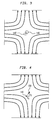
- Figure 3 which provides a view similar to that of Figure 2, the magnetic field pattern produced by section 110 is shown for the condition that currents in each of coils 112, 114, 116 and 118 are precisely equal, as would be produced by the serial connection of the coils in previous arrangements and the coils precisely identical in physical conformation and precisely positioned symmetrically about the mechanical axis of the yoke.
- the additional, usually superimposed, magnetic field which would be produced by section 120 is omitted in the interest of clarity.
- the currents in coils 112, 114, 116 and 118 are not equal, the magnetic field pattern will be changed.
- the distribution of the deflection field in a variable axis stigmator to bring about an axis shift is the same as that of the quadrupole. Consequently, the same coils (or electrodes, in an electrostatic stigmation arrangement) can be used for both functions.
- the first order terms of the mathematical field expansion for a general quadrupole arrangement comprising two quadrupole magnets rotated 45° with respect to each other are where B x,y is the magnetic flux density in each of the x and y directions, where a, b, and c to the geometry os coils and the currents therein, and, in the case of an electrical field E x,y where a, b and c relate to electrode geometry and the voltages thereon.
- nI x,y G(z) ⁇ nI x,y /R
- b(z) f(z) ⁇ nI b /R2
- c(z) f(z) ⁇ nI c /R2
- nI x,y denote the current in the deflector (dipole) for the fields in the x and y directions
- nI b and nI c denote the currents in the two quadrupoles, respectively, times the number of turns of the coils
- R denotes the distance of the coils from the axis of mechanical symmetry
- f(z) and g(z) denote functions for distributions of the respective fields along the axis, representing the geometry of the coils.
- the function and index b represent the quadrupole comprising coils 110, namely 112, 114, 116 and 118.
- the function and index c represents the quadrupole comprising coils 120, namely 122, 124, 126 and 128.
- n is equal to the number of turns of each coil of the yoke.
- x0 and y0 are unknown.
- the prior technique of alignment of the axis of the stigmator can be automated and the automatic collection of dynamic correction data can be included in a single automated process in accordance with the invention, as will be discussed with reference to Figure 5.
- FIG 5 the overall preferred implementation of the invention, including the automated set-up procedure is shown.
- the stigmator yoke 100 including sections 110 and 120 are schematically depicted in a view similar to that of Figure 1.
- the individual coils thereof 112 - 128 are identified with the same reference numerals as in Figure 1.
- Coil drivers 512 - 528 are connected thereto and are identified with the same least significant digits of the reference numerals as the coils to which they are connected, in the interest of clarity.
- the above-mentioned reference current input is not shown and may be included in a differential amplifier input stage to the drivers in a conventional manner.
- Positive, negative and gain adjustment inputs of each of the coil drivers 512 - 528 are shown. It is also to be understood that a single input may be provided for the positive or negative correction and internal circuitry provided for applying the correction increment in the desired sense, in a manner which is also conventional in amplifier design.
- dynamic correction means 506 may be used, if desired. If used, such a dynamic correction means would function in the same manner as is conventionally done for deflection circuits. That is, the x and y inputs are used to access corrected x' and y' values from look-up table 508 which are then substituted for the input x and y values or interpolation is done between look-up table values and the interpolated values x' and y' values substituted and for x and y and output to the appropriate coil drivers. Alternatively, if dynamic correction is not required or desired, x and y values can be directly applied to the coil driver circuits. Specifically, the x or x' signal is applied to drivers 512, 514, 522 and 528.
- the y or y' signal is applied to drivers 516, 518, 526 and 528. Internally of the driver circuits, the x and y deflection signals are applied as a multiplier of the positive or negative correction increment signal since the correction coefficients shown in Figure 6 are linear functions of x0 and y0.
- x and y inputs are only necessary if the electron beam axis varies with deflection. This will be the case if the stigmator yoke is placed to follow any deflection stage in the electron optical column of the electron beam deflection system. Therefore, an embodiment allowing for such inputs is preferred as being of most general application. Dynamic correction at least to the extent of scaling is also preferred since the axis offset distance will differ from that at the target.
- the previous technique of alignment by sensing deflection as stigmation current is altered can be emulated under computer control.
- any resulting deflection can be detected at position sensor 502.
- the x and y adjustments 534, 536, 544, 546, for each of the sections 110, 120 can be appropriately altered. This process can be repeated several times at high speed under programmed control of the set-up automation means until no deflection is observed when the coil driver gain is varied.
- the process can be repeated under programmed control at other locations of a target and further correction values entered in look-up table 508 to provide additional stigmator axis correction.
- This further correction can then be made dynamically in the same manner as dynamic deflection correction during operation of the e-beam tool.
- the axis of each of the quadrupoles is shifted to corresponding locations and the quadrupoles need not be at the same axial position, insofar as the axis shift is concerned. It should, therefore, be understood that in an application where only one quadrupole was used, the axis could be shifted in the same manner as either of quadrupoles 110 or 120.
- the quadrupoles are at the same axial position along the charged particle beam column, it is also possible to reduce the number of drivers utilized while retaining the ability to shift the axis of the pair of quadrupoles.
- the coils of either quadrupole could be connected in series and driven by a single driver while the coils of the other quadrupole would be separately driven, as described above.
- the net axis shift can be obtained regardless of which quadrupole axis is shifted in accordance with the invention. If the coils of quadrupole 120 are commonly driven (e.g.
- coils 112 - 118 are driven with the following currents: Coil 112: I1 - (I2x0 + I1y0)/R , Coil 114: -I1 - (I2x0 + I1y0)/R , Coil 116: I1 + (I1x0 + I2y0)/R , Coil 118: -I1 - (I1x0 + I2y0)/R .
- coils of quadrupole 110 are commonly driven (e.g. connected in series) with a current I1
- the net axis shift is obtained when coils 122 - 128 are driven with the following currents: Coil 122: -I2 + [I2(x0 + y0)/R ⁇ 2 , Coil 124: -I2 - [I2(x0 + y0)/R ⁇ 2 , Coil 126: I2 - [I2(x0 + y0)/R ⁇ 2 , Coil 128: I2 + [I2(x0 + y0)/R ⁇ 2 , In this latter case, it should be noted that the currents for coils 122 - 128 are completely independent of I1 which may yield simplification of computation for dynamic correction of astigmatism or other applications such as in the strong focussing of ion beam and other high energy beam applications noted above. To the extent that such simplification may be beneficially exploited, therefore, the orientation of coils as in quadru
- the invention provides a simple technique of shifting the magnetic axis of a stigmator yoke relative to the mechanical axis thereof by electrical means. This allows the alignment to be accomplished under automated control to eliminate manual mechanical adjustments and to allow automation of the corresponding portion of the set-up procedure for an e-beam tool. Further, the ability to electrically alter the magnetic axis of the stigmator yoke provides the capacity for dynamic correction of the stigmator axis to further increase accuracy of the e-beam tool or to provide flexibility in the location of the stigmator yoke along the electron optical column, or both.
Landscapes
- Chemical & Material Sciences (AREA)
- Analytical Chemistry (AREA)
- Physics & Mathematics (AREA)
- Electromagnetism (AREA)
- Electron Beam Exposure (AREA)
- Electron Sources, Ion Sources (AREA)
Applications Claiming Priority (2)
| Application Number | Priority Date | Filing Date | Title |
|---|---|---|---|
| US07/915,798 US5389858A (en) | 1992-07-16 | 1992-07-16 | Variable axis stigmator |
| US915798 | 2001-07-26 |
Publications (2)
| Publication Number | Publication Date |
|---|---|
| EP0580212A1 true EP0580212A1 (fr) | 1994-01-26 |
| EP0580212B1 EP0580212B1 (fr) | 1999-12-29 |
Family
ID=25436264
Family Applications (1)
| Application Number | Title | Priority Date | Filing Date |
|---|---|---|---|
| EP93201985A Expired - Lifetime EP0580212B1 (fr) | 1992-07-16 | 1993-07-07 | Stigmateur d'axe variable |
Country Status (4)
| Country | Link |
|---|---|
| US (2) | US5389858A (fr) |
| EP (1) | EP0580212B1 (fr) |
| JP (1) | JPH06103946A (fr) |
| DE (1) | DE69327429T2 (fr) |
Families Citing this family (23)
| Publication number | Priority date | Publication date | Assignee | Title |
|---|---|---|---|---|
| US5389858A (en) * | 1992-07-16 | 1995-02-14 | International Business Machines Corporation | Variable axis stigmator |
| US5546319A (en) * | 1994-01-28 | 1996-08-13 | Fujitsu Limited | Method of and system for charged particle beam exposure |
| US5642441A (en) * | 1995-10-24 | 1997-06-24 | Neopath, Inc. | Separation apparatus and method for measuring focal plane |
| US5635719A (en) * | 1996-07-23 | 1997-06-03 | International Business Machines Corporation | Variable curvilinear axis deflection means for particle optical lenses |
| JPH1040848A (ja) * | 1996-07-25 | 1998-02-13 | Nikon Corp | 荷電粒子線装置 |
| US5757010A (en) * | 1996-12-18 | 1998-05-26 | International Business Machines Corporation | Curvilinear variable axis lens correction with centered dipoles |
| JP2992688B2 (ja) * | 1998-05-19 | 1999-12-20 | セイコーインスツルメンツ株式会社 | 複合荷電粒子ビーム装置 |
| JP3041600B2 (ja) * | 1998-05-19 | 2000-05-15 | セイコーインスツルメンツ株式会社 | 複合荷電粒子ビーム装置 |
| DE19907858C1 (de) * | 1999-02-24 | 2000-10-05 | Leica Microsys Lithography Ltd | Vorrichtung zur elektrostatischen Ablenkung eines Korpuskularstrahles |
| US6420713B1 (en) | 1999-04-28 | 2002-07-16 | Nikon Corporation | Image position and lens field control in electron beam systems |
| DE60134922D1 (de) * | 2000-08-14 | 2008-09-04 | Elith Llc | Lithographischer Apparat |
| DE10044199B9 (de) | 2000-09-07 | 2005-07-28 | Carl Zeiss Smt Ag | Ablenkanordnung und Projektionssystem für geladene Teilchen |
| US20020063567A1 (en) * | 2000-11-30 | 2002-05-30 | Applied Materials, Inc. | Measurement device with remote adjustment of electron beam stigmation by using MOSFET ohmic properties and isolation devices |
| DE10109965A1 (de) | 2001-03-01 | 2002-09-12 | Zeiss Carl | Teilchenoptische Linsenanordnung und Verfahren unter Einsatz einer solchen Linsenanordnung |
| JP2002299207A (ja) | 2001-03-29 | 2002-10-11 | Toshiba Corp | 荷電粒子ビーム描画装置 |
| JP4855875B2 (ja) * | 2006-09-06 | 2012-01-18 | 富士フイルム株式会社 | 電子ビーム描画装置及び電子ビームのずれ補償方法 |
| EP2166557A1 (fr) * | 2008-09-22 | 2010-03-24 | FEI Company | Procédé de correction de distorsions dans un appareil optique corpusculaire |
| US8604443B2 (en) * | 2009-11-13 | 2013-12-10 | Varian Semiconductor Equipment Associates, Inc. | System and method for manipulating an ion beam |
| US9053900B2 (en) * | 2012-04-03 | 2015-06-09 | Kla-Tencor Corporation | Apparatus and methods for high-resolution electron beam imaging |
| US9455115B2 (en) * | 2014-12-17 | 2016-09-27 | Carl Zeiss Microscopy Gmbh | Method of adjusting a stigmator in a particle beam apparatus and a Particle beam system |
| WO2018122953A1 (fr) * | 2016-12-27 | 2018-07-05 | 株式会社日立ハイテクノロジーズ | Correcteur d'aberration et microscope électronique |
| JP7440191B2 (ja) * | 2021-01-20 | 2024-02-28 | 株式会社日立製作所 | 荷電粒子ビーム偏向装置および粒子線治療システム |
| CN119764148B (zh) * | 2024-12-26 | 2025-10-21 | 东方晶源微电子科技(北京)股份有限公司 | 一种电子束成像设备的消像散方法、产品及设备 |
Citations (5)
| Publication number | Priority date | Publication date | Assignee | Title |
|---|---|---|---|---|
| DE1179313B (de) * | 1961-05-16 | 1964-10-08 | Zeiss Carl Fa | Einrichtung zur Kompensation des Astigmatismus von Elektronenlinsen und Schaltungsanordnung zum Betrieb der Einrichtung |
| GB2215088A (en) * | 1987-02-16 | 1989-09-13 | Jeol Ltd | Automatically correcting astigmatism in a scanning electron microscope |
| EP0331859A2 (fr) * | 1988-01-11 | 1989-09-13 | International Business Machines Corporation | Déflexion télécentrique sur champs secondaires par lentille à immersion d'axe variable |
| DE3929774A1 (de) * | 1989-09-02 | 1991-03-07 | Hans W P Dipl Phys Dr Koops | Korpuskularstrahloptisches geraet mit kompensierten beleuchtungs- und abbildungsfehlern zur korpuskelbestrahlung eines praeparates in form eines flaechenmusters |
| EP0419287A2 (fr) * | 1989-09-21 | 1991-03-27 | Kabushiki Kaisha Toshiba | Méthode de correction de l'astigmatisme d'un faisceau dont la section présente une forme variable |
Family Cites Families (14)
| Publication number | Priority date | Publication date | Assignee | Title |
|---|---|---|---|---|
| US2919381A (en) * | 1956-07-25 | 1959-12-29 | Farrand Optical Co Inc | Electron lens |
| US3152238A (en) * | 1962-05-11 | 1964-10-06 | United Aircraft Corp | Electron beam centering apparatus |
| AT275617B (de) * | 1968-02-23 | 1969-10-27 | Zeiss Carl Fa | Verfahren und Anordnung zur Justierung des Elektronenstrahles in einem Elektronenmikroskop |
| DE1802450B1 (de) * | 1968-09-02 | 1970-07-02 | Siemens Ag | Verfahren zur Scharfstellung eines korpuskularstrahloptischen Bildes |
| JPS5492050A (en) * | 1977-12-29 | 1979-07-20 | Jeol Ltd | Method and apparatus for astigmatic correction of scanning electronic microscope and others |
| JPS5688246A (en) * | 1979-12-20 | 1981-07-17 | Jeol Ltd | Electron beam device |
| US4397230A (en) * | 1982-02-10 | 1983-08-09 | Hunt Arthur J | Screw press improvements |
| US4567369A (en) * | 1982-06-18 | 1986-01-28 | National Research Development Corporation | Correction of astigmatism in electron beam instruments |
| AT388628B (de) * | 1986-01-31 | 1989-08-10 | Ims Ionen Mikrofab Syst | Einrichtung fuer projektionsgeraete |
| JPH073774B2 (ja) * | 1986-10-08 | 1995-01-18 | 株式会社日立製作所 | 電子顕微鏡 |
| US4967380A (en) * | 1987-09-16 | 1990-10-30 | Varian Associates, Inc. | Dual channel signal processor using weighted integration of log-ratios and ion beam position sensor utilizing the signal processor |
| GB2213353A (en) * | 1987-12-04 | 1989-08-09 | Philips Electronic Associated | Stigmator lens current control circuit |
| US4962309A (en) * | 1989-08-21 | 1990-10-09 | Rockwell International Corporation | Magnetic optics adaptive technique |
| US5389858A (en) * | 1992-07-16 | 1995-02-14 | International Business Machines Corporation | Variable axis stigmator |
-
1992
- 1992-07-16 US US07/915,798 patent/US5389858A/en not_active Expired - Lifetime
-
1993
- 1993-06-30 JP JP5161084A patent/JPH06103946A/ja active Pending
- 1993-07-07 EP EP93201985A patent/EP0580212B1/fr not_active Expired - Lifetime
- 1993-07-07 DE DE69327429T patent/DE69327429T2/de not_active Expired - Lifetime
-
1994
- 1994-08-26 US US08/296,138 patent/US5481164A/en not_active Expired - Lifetime
Patent Citations (5)
| Publication number | Priority date | Publication date | Assignee | Title |
|---|---|---|---|---|
| DE1179313B (de) * | 1961-05-16 | 1964-10-08 | Zeiss Carl Fa | Einrichtung zur Kompensation des Astigmatismus von Elektronenlinsen und Schaltungsanordnung zum Betrieb der Einrichtung |
| GB2215088A (en) * | 1987-02-16 | 1989-09-13 | Jeol Ltd | Automatically correcting astigmatism in a scanning electron microscope |
| EP0331859A2 (fr) * | 1988-01-11 | 1989-09-13 | International Business Machines Corporation | Déflexion télécentrique sur champs secondaires par lentille à immersion d'axe variable |
| DE3929774A1 (de) * | 1989-09-02 | 1991-03-07 | Hans W P Dipl Phys Dr Koops | Korpuskularstrahloptisches geraet mit kompensierten beleuchtungs- und abbildungsfehlern zur korpuskelbestrahlung eines praeparates in form eines flaechenmusters |
| EP0419287A2 (fr) * | 1989-09-21 | 1991-03-27 | Kabushiki Kaisha Toshiba | Méthode de correction de l'astigmatisme d'un faisceau dont la section présente une forme variable |
Also Published As
| Publication number | Publication date |
|---|---|
| US5389858A (en) | 1995-02-14 |
| US5481164A (en) | 1996-01-02 |
| JPH06103946A (ja) | 1994-04-15 |
| EP0580212B1 (fr) | 1999-12-29 |
| DE69327429T2 (de) | 2000-06-08 |
| DE69327429D1 (de) | 2000-02-03 |
Similar Documents
| Publication | Publication Date | Title |
|---|---|---|
| EP0580212B1 (fr) | Stigmateur d'axe variable | |
| EP0129681B1 (fr) | Système de projection par faisceau électronique avec lentille à immersion d'axe variable | |
| EP0051733B1 (fr) | Dispositif de projection par rayons à électrons | |
| EP2023373B1 (fr) | Appareil de faisceau à particules chargées et procédé d'irradiation | |
| EP4120314B1 (fr) | Lentille électromagnétique | |
| EP0331859B1 (fr) | Déflexion télécentrique sur champs secondaires par lentille à immersion d'axe variable | |
| JP2000058450A (ja) | 荷電粒子線露光装置における補正器の最適化方法及び荷電粒子線露光装置 | |
| US5136167A (en) | Electron beam lens and deflection system for plural-level telecentric deflection | |
| EP0133016A2 (fr) | Lentille magnétique à intervalles multiples par la focalisation des faisceaux de particules chargées | |
| US5757010A (en) | Curvilinear variable axis lens correction with centered dipoles | |
| EP0883891B1 (fr) | Procede d'exploitation d'un appareil optique a particules | |
| US5708274A (en) | Curvilinear variable axis lens correction with crossed coils | |
| JPH10188870A (ja) | シフトした双極子による曲線可変軸レンズ補正 | |
| EP0088457B1 (fr) | Appareil à faisceau de particules chargées | |
| US5285074A (en) | Dynamic compensation of non-linear electron beam landing angle in variable axis lenses | |
| US4798953A (en) | Electronic beam device for projecting an image of an object on a sample | |
| EP0083246B1 (fr) | Système d'exposition par faisceau électronique balayé | |
| US4101813A (en) | Double deflection system for an electron beam device | |
| US2976457A (en) | Electron lens | |
| KR20240100270A (ko) | 영구자석 및 전자기 컴포넌트를 갖는 조정 가능한 자기 렌즈 | |
| JPH0234426B2 (fr) | ||
| US20240258065A1 (en) | Method of operating a particle beam system and computer program product | |
| Zhu et al. | Comprehensive analysis of electron optical design of SCALPEL-HT/Alpha | |
| Hosokawa et al. | Electron beam optical system with large field coverage for submicron lithography | |
| JPH10302691A (ja) | 投影レンズ系 |
Legal Events
| Date | Code | Title | Description |
|---|---|---|---|
| PUAI | Public reference made under article 153(3) epc to a published international application that has entered the european phase |
Free format text: ORIGINAL CODE: 0009012 |
|
| AK | Designated contracting states |
Kind code of ref document: A1 Designated state(s): DE FR GB |
|
| 17P | Request for examination filed |
Effective date: 19940519 |
|
| 17Q | First examination report despatched |
Effective date: 19960228 |
|
| GRAG | Despatch of communication of intention to grant |
Free format text: ORIGINAL CODE: EPIDOS AGRA |
|
| GRAG | Despatch of communication of intention to grant |
Free format text: ORIGINAL CODE: EPIDOS AGRA |
|
| GRAH | Despatch of communication of intention to grant a patent |
Free format text: ORIGINAL CODE: EPIDOS IGRA |
|
| GRAH | Despatch of communication of intention to grant a patent |
Free format text: ORIGINAL CODE: EPIDOS IGRA |
|
| GRAA | (expected) grant |
Free format text: ORIGINAL CODE: 0009210 |
|
| AK | Designated contracting states |
Kind code of ref document: B1 Designated state(s): DE FR GB |
|
| REF | Corresponds to: |
Ref document number: 69327429 Country of ref document: DE Date of ref document: 20000203 |
|
| ET | Fr: translation filed | ||
| PLBE | No opposition filed within time limit |
Free format text: ORIGINAL CODE: 0009261 |
|
| 26N | No opposition filed | ||
| REG | Reference to a national code |
Ref country code: GB Ref legal event code: IF02 |
|
| PGFP | Annual fee paid to national office [announced via postgrant information from national office to epo] |
Ref country code: GB Payment date: 20030702 Year of fee payment: 11 |
|
| PG25 | Lapsed in a contracting state [announced via postgrant information from national office to epo] |
Ref country code: GB Free format text: LAPSE BECAUSE OF NON-PAYMENT OF DUE FEES Effective date: 20040707 |
|
| GBPC | Gb: european patent ceased through non-payment of renewal fee |
Effective date: 20040707 |
|
| PGFP | Annual fee paid to national office [announced via postgrant information from national office to epo] |
Ref country code: DE Payment date: 20120723 Year of fee payment: 20 Ref country code: FR Payment date: 20120731 Year of fee payment: 20 |
|
| REG | Reference to a national code |
Ref country code: DE Ref legal event code: R071 Ref document number: 69327429 Country of ref document: DE |
|
| PG25 | Lapsed in a contracting state [announced via postgrant information from national office to epo] |
Ref country code: DE Free format text: LAPSE BECAUSE OF EXPIRATION OF PROTECTION Effective date: 20130709 |