EP0580251A1 - Rasoir électrique à joint anti-poussières de cheveux - Google Patents
Rasoir électrique à joint anti-poussières de cheveux Download PDFInfo
- Publication number
- EP0580251A1 EP0580251A1 EP93202150A EP93202150A EP0580251A1 EP 0580251 A1 EP0580251 A1 EP 0580251A1 EP 93202150 A EP93202150 A EP 93202150A EP 93202150 A EP93202150 A EP 93202150A EP 0580251 A1 EP0580251 A1 EP 0580251A1
- Authority
- EP
- European Patent Office
- Prior art keywords
- hair dust
- dust seal
- side walls
- shaving head
- shaving
- Prior art date
- Legal status (The legal status is an assumption and is not a legal conclusion. Google has not performed a legal analysis and makes no representation as to the accuracy of the status listed.)
- Granted
Links
Images

Classifications
-
- B—PERFORMING OPERATIONS; TRANSPORTING
- B26—HAND CUTTING TOOLS; CUTTING; SEVERING
- B26B—HAND-HELD CUTTING TOOLS NOT OTHERWISE PROVIDED FOR
- B26B19/00—Clippers or shavers operating with a plurality of cutting edges, e.g. hair clippers, dry shavers
- B26B19/38—Details of, or accessories for, hair clippers, or dry shavers, e.g. housings, casings, grips, guards
- B26B19/3853—Housing or handle
-
- B—PERFORMING OPERATIONS; TRANSPORTING
- B26—HAND CUTTING TOOLS; CUTTING; SEVERING
- B26B—HAND-HELD CUTTING TOOLS NOT OTHERWISE PROVIDED FOR
- B26B19/00—Clippers or shavers operating with a plurality of cutting edges, e.g. hair clippers, dry shavers
- B26B19/02—Clippers or shavers operating with a plurality of cutting edges, e.g. hair clippers, dry shavers of the reciprocating-cutter type
- B26B19/04—Cutting heads therefor; Cutters therefor; Securing equipment thereof
-
- B—PERFORMING OPERATIONS; TRANSPORTING
- B26—HAND CUTTING TOOLS; CUTTING; SEVERING
- B26B—HAND-HELD CUTTING TOOLS NOT OTHERWISE PROVIDED FOR
- B26B19/00—Clippers or shavers operating with a plurality of cutting edges, e.g. hair clippers, dry shavers
- B26B19/26—Clippers or shavers operating with a plurality of cutting edges, e.g. hair clippers, dry shavers of the type performing different methods of operation simultaneously, e.g. reciprocating and oscillating; of the type having two or more heads of differing mode of operation
-
- B—PERFORMING OPERATIONS; TRANSPORTING
- B26—HAND CUTTING TOOLS; CUTTING; SEVERING
- B26B—HAND-HELD CUTTING TOOLS NOT OTHERWISE PROVIDED FOR
- B26B19/00—Clippers or shavers operating with a plurality of cutting edges, e.g. hair clippers, dry shavers
- B26B19/38—Details of, or accessories for, hair clippers, or dry shavers, e.g. housings, casings, grips, guards
-
- B—PERFORMING OPERATIONS; TRANSPORTING
- B26—HAND CUTTING TOOLS; CUTTING; SEVERING
- B26B—HAND-HELD CUTTING TOOLS NOT OTHERWISE PROVIDED FOR
- B26B19/00—Clippers or shavers operating with a plurality of cutting edges, e.g. hair clippers, dry shavers
- B26B19/38—Details of, or accessories for, hair clippers, or dry shavers, e.g. housings, casings, grips, guards
- B26B19/3853—Housing or handle
- B26B19/3866—Seals or dampers
-
- B—PERFORMING OPERATIONS; TRANSPORTING
- B26—HAND CUTTING TOOLS; CUTTING; SEVERING
- B26B—HAND-HELD CUTTING TOOLS NOT OTHERWISE PROVIDED FOR
- B26B19/00—Clippers or shavers operating with a plurality of cutting edges, e.g. hair clippers, dry shavers
- B26B19/02—Clippers or shavers operating with a plurality of cutting edges, e.g. hair clippers, dry shavers of the reciprocating-cutter type
- B26B19/04—Cutting heads therefor; Cutters therefor; Securing equipment thereof
- B26B19/10—Cutting heads therefor; Cutters therefor; Securing equipment thereof involving two or more different types of reciprocating cutting elements, e.g. a pair of toothed shearing elements combined with a pair of perforated cutting elements or a combined toothed and perforated cutting assembly
- B26B19/102—Cutting heads therefor; Cutters therefor; Securing equipment thereof involving two or more different types of reciprocating cutting elements, e.g. a pair of toothed shearing elements combined with a pair of perforated cutting elements or a combined toothed and perforated cutting assembly with a secondary cutting unit being translated or slid into an operating position
Definitions
- the invention relates to a razor with a shaving head with a film-like upper knife and a lower knife abutting against it, both of which have a curved cutting area with respect to an axis, with a motor-driven drive device for the lower knife, which has a block-shaped drive part has, with which the lower knife at least one movement parallel to the direction of the axis can be given, and with a hair dust seal made of elastic material, which is hood-like and trough-like and is arranged around the block-shaped drive part and four side walls and one the four side walls on their Limiting ends facing the lower knife, having a passage opening for an output section of the drive part, with which the hair dust seal is connected to the drive part, and one of the four side walls on their side facing away from the lower knife Has ends bordering edge area with which the hair dust seal rests against a housing-stationary zone.
- a shaver according to the type mentioned above is known for example from EP 0 480 499 A1.
- the hood-like and trough-like hair dust seal has side walls which are essentially continuous and mainly flat.
- the hair dust seal it has been shown that when the lower knife is driven, the hair dust seal that is also moved in the area of its larger side walls running parallel to the direction of the axis executes transverse movements to these side walls with relatively large amplitudes and therefore practically acts like a diaphragm of a loudspeaker the hair dust seal causes a relatively high level of noise. This is annoying, which is why such a formation of a hair dust seal has proven to be unfavorable in practice.
- the invention has set itself the task of avoiding the difficulties mentioned above and to achieve a formation of a hair dust seal in a shaver according to the type mentioned in the first paragraph, in which there is practically no or very little noise.
- the invention is characterized in that the hair dust seal has a gradation extending over all four side walls and that the gradation has an undulating course at least in the two opposite side walls running parallel to the direction of the axis.
- the wall sections of those side walls of the hair dust seal in which a gradation having a wavy course is provided, can execute a relative movement made possible by the wavy gradation, which mainly takes place parallel to the respective side wall and which results has that practically no or only very small movement components running transversely to the wall sections occur within the wall sections.
- the drive device in the area of the hair dust seal does not have a block-shaped drive part, but a pin-shaped drive part, and the hair dust seal is not a hood-like and trough-like design, but instead has a rotationally symmetrical, frustoconical design.
- This hair dust seal is also provided with a circumferential gradation. However, this gradation always has the same axial level along the entire circumference.
- the gradation of the hood-like and trough-like hair dust seal of a shaving apparatus according to the invention points at least in the two parallel to the direction of the axis running opposite side walls of the hair dust seal on a wavy course.
- the gradation can have an essentially sinusoidal shape, for example, in its areas with a wavy shape.
- the price has proven to be particularly advantageous if the gradation is sawtooth-shaped in its areas with a wavy course. In the case of such a sawtooth-shaped course of the gradation, a particularly low level of noise was found in practice by means of a hair dust seal in such a shaving apparatus.
- edge of the hair dust seal rests in a recess on the inside of the housing that is open to the shaving head and the edge region of the hair dust seal presses against an area of the shaving head with an edge region zone that is exposed to the deposit.
- the edge region of the hair dust seal is used not only for fastening the hair dust seal, but also as a damping element which prevents mechanical vibrations between the shaving head and the housing of the shaving apparatus and thereby prevents disruptive noise.
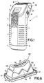
- FIG. 1 shows an oblique view of a razor according to the invention with a shaving head.
- 2 shows, on a larger scale than in FIG. 1, a cross section of the shaving head with a shaving head frame and a foil frame that is adjustable relative to the shaving head frame, and the area of the shaving apparatus according to FIG. 1 adjoining the shaving head, in which a hair dust seal is provided .
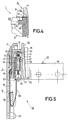
- 3 shows a side view and partly in section the shaving head and the area of the shaving apparatus adjacent to the shaving head according to FIGS. 1 and 2, the hair dust seal being shown in a side view. 4 shows, on a larger scale than in FIG.
- FIG. 3 a detail of the shaving apparatus according to FIGS. 1, 2 and 3, which is outlined in FIG. 3 with a circle.
- 5 shows, analogously to FIG. 2, on a larger scale than FIG. 2, part of the shaving head of the razor according to FIGS. 1, 2 and 3 without a film knife connected to the film frame.
- 6 shows an oblique view of the hair dust seal of the shaver according to FIGS. 1, 2 and 3.
- a shaving apparatus 1 which has a housing 2 which consists of two housing halves 3 and 4 which are connected to one another and which are closed at the bottom by a trough-shaped housing part 5.
- a side cutter (not visible in FIG. 1) is provided, which is adjustable between a rest position retracted into the shaver 1 and an operating position pushed out of the shaver 1 and which is covered in its rest position with a cover plate 6, so that only a knife carrier 7 of the side cutter is partially visible.
- the shaving apparatus 1 has a handle 8 which is connected to the knife carrier 7 of the side cutter via a roller-type flexible connecting part 9.
- a shaving head 10 which is detachably connected to the housing 2, is placed and held on the housing 2 of the shaving apparatus 1.
- the shaving head 10 has a film-like upper knife, which can be covered with the help of a roller shutter-like cover 11, which is essentially parallel to the main wall of the housing half 4 between a cover position shown in FIG. 1, in which it covers the film-like upper knife in a protective manner, and one Release position is adjustable, in which it releases the film-like upper knife to enable a shaving operation.
- the shaving head 10 of the shaving apparatus 1 is described below with reference to FIGS. 2, 3 and 5.
- the shaving head 10 has a metal shaving head frame 12 made of die-cast zinc, which has a first longitudinal side wall 13 and a second longitudinal side wall 14 as well as a first transverse side wall 15 and a second transverse side wall 16.
- a first chrome-plated plastic part 17 or 18 and a second plastic part 19 or 20 are connected to the shaving head frame 12, namely in that first the chrome-plated plastic parts 17 and 18 face away from the shaver 1 Side are pushed onto the shaving head frame 12, after which the two other plastic parts 19 and 20 with the shaving head 10 still removed from the shaving apparatus 1, as shown in FIG. 5, from the side facing the shaving apparatus 1 onto the two chromed plastic parts 17 and 18 pushed on and connected by means of a pin-hole connection 21 and 22, respectively, by the pins falling into the holes of the pin-hole connections 21 and 22.
- the plastic parts 17, 18 and 19, 20 are to be regarded as components of the shaving head frame 12, which is thus made of several parts. But it could also be formed in one piece.
- the two plastic parts 19 and 20 are elongated in relation to the shaving head frame 12 in the direction of the shaving apparatus 1.
- a locking lug 23 or 24 is provided, which can be held by means of a locking hook 25 or 26.
- the shaving head 10 is held on the housing 2 of the shaving apparatus 1.
- the locking hooks 25 and 26 are each provided on a manually actuable push button 27 or 28, which are held adjustable in the housing 2 of the shaver 1 and which, depending on the force of a leaf spring 29 or 30 supported in the housing 2, toward the interior of the device are adjustable to release the shaving head 10 for removing the same.
- a foil frame 31 is adjustably held on the shaving head frame 12, namely in the direction of an axis 32 perpendicular to an apex line of the foil-like upper knife.
- the foil frame 31 can be inserted into and in the shaving head frame 12 through the side or frame opening of the shaving head frame 12 facing the housing 2 hold on.
- the film frame 31, like the shaving head frame 12, has a first longitudinal side wall 33 and a second longitudinal side wall 34 as well as a first transverse side wall 35 and a second transverse side wall 36.
- a cylindrical extension 39 and 40 is connected to each of the two transverse side walls 35 and 36 via a web 37 and 38, respectively. In Fig.2 only the cylindrical extension 40 is shown in section and from Fig.5 only the cylindrical extension 39 can be seen.
- the cylindrical extension 39 is received in a hollow cylindrical guide chamber 41 provided in the first transverse side wall 15 of the shaving head frame 12 with only little play.
- the guide chamber 41 merges into an exemption slot 42 through which the web 37 is passed.
- the cylindrical extension 40 is accommodated in a guide chamber 43 which is provided in the second transverse side wall 16 of the shaving head frame 12 and which is essentially rectangular in cross section, with a relatively large amount of play in the direction of the longitudinal side walls 13 and 14 and 33 and 34, but with only a small amount of play in the transverse direction, which merges into an exemption slot 44 through which the web 38 is passed.
- the film frame 31 is displaceably guided relative to the shaving head frame 12 in the direction of the axis 32.
- a circumferentially closed hollow cylindrical channel 45 and 46 is provided in each of the two cylindrical lugs 39 and 40, as shown in FIG. 2 for the lug 40 and in FIG. 5 for the lug 39.
- a sleeve 47 and 48 is slidably received, which forms a piston-like pressure part.
- Each sleeve 47 or 48 protrudes with its substantially closed end 49 or 50 through a hole provided in the ceiling area 51 or 52 of the extension 39 or 40 from the channel 45 or 46 and is supported on a ceiling-side boundary wall 53 or 54 of the guide chambers 41 and 43, respectively.
- each helical compression spring 57 or 58 is received, which is guided up to the sleeve bottom of the sleeve 47 or 48. With its end facing away from the sleeve bottom, each helical compression spring 57 or 58 is supported on a closing part 59 or 60 which closes off the channel 45 or 46 and is formed by a press-in part pressed into the channel 45 or 46.
- the force of the two helical compression springs 57 and 58 achieves resilient tensioning between the film frame 31 and the shaving head frame 12.
- the helical compression springs 57 and 58 seek to adjust the film frame 31 relative to the shaving head frame 12 held on the housing 2 of the shaving apparatus 1 with the locking hooks 25 and 26 parallel to the axis 32 in the direction of the shaving apparatus 1.
- the helical compression springs 57 and 58 are advantageously captive and free from contamination protected within the channels 45 and 46 and the helical compression springs 57 and 58 act on the shaving head frame 12 via the sleeves 47 and 48, the cylindrical projections 39 and 40 holding the press-in parts 59 and 60 on the one hand and the boundary walls 53 and 54 on the ceiling side on the other Form engagement sections on the film frame 31 and on the shaving head frame 12 for the helical compression springs 57 and 58.
- the present shaving apparatus 1 is particularly simple and advantageously provided the following measures.
- the two transverse side walls 15 and 16 of the shaving head frame 12 are elongated in relation to the two transverse side walls 35 and 36 of the film frame 31 in the direction of the housing 2 of the shaving apparatus 1 and each have a wall extension 61 or in the direction of the shaving apparatus 1 projecting from the shaving head frame 12 or 62, which are covered by the plastic parts 19 and 20.
- These wall extensions 61 and 62 are essentially U-shaped, a connecting web 63 and 64 being provided between the two leg parts of each wall extension 61 and 62, respectively. With each of the two connecting webs 63 and 64, a leaf spring 65 or 66 is provided, which extends essentially in the direction of the wall extension 61 or 62 towards the film frame 31 and is provided as a positively acting holding device.
- Both leaf springs 65 and 66 serve as adjustable bolts, with the free end 67 and 68 of the film frame 31 in the shaving head frame 12 can be positively retained, namely in that the free ends 67 and 68 of the leaf springs 65 and 66 each in the range Support cylindrical lugs 39 and 40 and the locking pieces 59 and 60 located there and in this way absorb the forces exerted by the helical compression springs 57 and 58, respectively.
- the film frame 31 is securely held in the shaving head frame 12 with the simplest of means, the design of the latches provided for holding as leaf springs 65 and 66 further having the advantage of a particularly simple insertion of the film frame 31 into the shaving head frame 12 and also the advantage of a particularly simple one Removing the film frame 31 from the shaving head frame 12 entails.
- the film frame 31 is simply pushed through between the two leaf springs 65 and 66 provided as latches with adjustment thereof, the sleeves 47 and 48 also advantageously coming into operative connection with the boundary walls 53 and 54 provided for this purpose.
- the two leaf springs 65 and 66 are simply pushed apart by hand, after which the film frame 31 is first pressed out under the action of the helical compression springs 57 and 58 from the shaving head frame 12, so that the film frame 31 is subsequently pulled out of the shaving head frame 12 unhindered can be.
- the film frame 31 each has a resilient tab 69 or 70 projecting obliquely from the relevant longitudinal side wall 33 or 34. These tabs 69 and 70 are integrally connected to the film frame 31.
- the flaps 69 and 70 are each supported on the longitudinal side walls 13 and 14 of the shaving head frame 12, as a result of which the play existing between the guide chambers 41 and 43 of the shaving head frame 12 and the cylindrical projections 39 and 40 of the film frame 31 transversely to the longitudinal side walls 13 and 14 as well as 33 and 34 is compensated for, so that no noise development based on such a game is possible.
- the foil frame 31 serves to hold the already mentioned foil-like upper knife of the shaving head 10, which is formed here by a so-called sieve shear foil 71, which is connected to the two longitudinal side walls 33 and 34 of the foil frame 31 with two longitudinal edge regions in a manner not shown.
- the sieve shear foil 71 assumes a shape that is arched with respect to an axis 72 oriented perpendicular to the axis 32, so that its area provided with through-openings forms a cutting area that is arched with respect to the axis 72.
- a bottom knife 73 interacts with the sieve shear foil 71, which in the present shaving apparatus 1 has a sheet-like or foil-like design, but the foil thickness of the bottom knife 73 is greater than the foil thickness of the sieve shear foil 71.
- the foil-like or blade-like bottom knife 73 is at one Lower knife carrier 74 is attached, with which the longitudinal side edges of the lower knife 73 are connected in a manner not shown.
- the lower knife 73 also takes a curved course with respect to the axis 72.
- the lower knife 73 is also in provided in its central region with through-openings, this central region likewise representing a cutting region which is curved in relation to the axis 72.
- the lower knife carrier 74 together with the film-like lower knife 73 fastened thereon is connected to a drive part 75 of a drive device 76 of the shaving apparatus 1, the lower knife carrier 74 being placed on a removal section 77 of the drive part 75 and being held in place by means of a latching connection.
- the drive device 76 is briefly described below. With regard to the drive device 76, reference is made to EP 0 480 499 A1, from which a shaver 1 with such a drive device is known and whose disclosure content is hereby incorporated by reference by reference to the same (herewith incorporated by reference).
- the drive device 76 has a motor 78, to the rotatably drivable motor shaft of which is not visible in FIG. 2, a rotatably drivable eccentric 79 is connected, from which an eccentric pin 80 projecting eccentrically with respect to the shaft of the motor 78 protrudes.
- the eccentric 79 is passed through an opening 81 in an essentially V-shaped connecting piece 82 of a swing bridge 83.
- the swing bridge has, in addition to the V-shaped connecting piece 82, two webs 84 and 85, each of which is provided with two film hinge areas 86 and 87 or 88 and 89 and which each have a connecting area 90 or adjacent to a film hinge area 86 or 88.
- 91 are connected to the V-shaped connecting piece 82 and are each fastened to a device-stationary bearing section 94 or 95 with a fastening area 92 or 93 connected to the other film hinge area 87 or 89.
- the eccentric pin 80 of the eccentric 79 protrudes into a bore 96 of a transmission part 98 which is cylindrical with respect to an axis 97 parallel to the axis 72 and from which two extensions 99 and 100, which are also coaxial with the axis 97, project laterally. These extensions 99 and 100 protrude into two bearing slots 101 and 102 which are open in the direction of the eccentric 79 and which are provided in two tabs 103 and 104 projecting from the drive part 75.
- the drive part 75 which can be driven by the eccentric pin 80 via the transmission part 98, has two cylindrical projections 105 and 106 which project laterally and coaxially to the axis 72 and which are in bearing slots in the connecting areas 90 and 91 which are open towards the lower knife 73 are rotatably or pivotally mounted.
- the webs 84 and 85 of the swing bridge 83 are rigid in the direction of the axis 32, so that the drive part 75 which is pivotably mounted in the connecting regions 90 and 91 and the lower knife 73 connected to the drive part 75 via the lower knife carrier 74 are practically negligible or only negligible Small movement in the direction of the axis 32 can perform.
- the webs 84 and 85 of the swing bridge 83 are, however, very movable in the direction of the axis 72, so that the lower knife 73 can execute a reciprocating swinging movement parallel to the axis 72.
- the lower knife 73 is additionally also given a pivoting movement about the axis 72 via the drive device 76 described above, which is superimposed on the reciprocating movement parallel to the axis 72 , so that in the present razor 1, the lower knife 73 performs a combined movement, which is composed of a linear reciprocating movement and a pivoting movement.
- the lower knife 73 is thus mounted rigidly in the direction of the axis 32.
- the sieve shear foil 71 is pressed against the lower knife 73 mounted in this way in that the sieve shear foil 71 attached to the foil frame 31 is loaded by the helical compression springs 57 and 58, which are supported on the shaving head frame 12 via the sleeves 47 and 48.
- the sieve shear foil 71 is spring-loaded in the manner described above on the lower knife 73, which is also essentially foil-like in this case.
- This springing ensures that the screen shaving foil 71 and the foil-like lower knife 73 are always in perfect contact with one another, so that a perfect shaving performance and shaving quality is ensured, the shaving performance of the shaving apparatus 1 being particularly high due to the combined movement of the lower blade 73.
- the shaving apparatus 1 has a hair dust seal 107.
- the hair dust seal 107 consists of an elastic material, namely rubber.
- the hair dust seal 107 is hood-like and trough-like and arranged around the block-shaped drive part 75.
- the hair dust seal 107 has four side walls 108, 109, 110 and 111. Furthermore, the hair dust seal 107 has an end region 113 which delimits the four side walls 108, 109, 110 and 111 at its ends facing the lower knife 73 and has a passage opening 112 for the beating section 77 of the drive part 75, with which the hair dust seal 107 is connected to the drive part 75 is.
- the drive part 75 has a closed circumferential groove 114, into which the hair dust seal 107 is inserted with its wall sections of the end region 113 surrounding the passage opening 112. Furthermore, the hair dust seal 107 has an edge region 115 which delimits the four side walls 108, 109, 110 and 111 at its ends facing away from the lower knife 73 and by means of which the hair dust seal 107 rests against a housing-stationary zone.
- the hair dust seal 107 lies with its edge region 115 in a shoulder 116 on the inside of the housing and open towards the shaving head 10. Furthermore, the dimension of the edge region 115 in the height direction of the shoulder 116 is selected such that the edge region 115 of the hair dust seal 107, with an edge region zone 117 exposed relative to the shoulder 116, presses against a region 118 of the shaving head 10 or its shaving head frame 12. As a result, mechanical vibrations between the housing 2 of the shaving apparatus 1 and the shaving head 10 or its shaving head frame 12 are prevented, so that no noise caused by such vibrations can occur and a quietly working shaving apparatus is obtained.
- the hair dust seal 107 is fastened in the shaving apparatus 1 with the aid of two resilient brackets 119 and 120.
- the resilient brackets 119 and 120 are passed through clearances 121 in the corners of the edge region 115 of the hair dust seal 107 and brackets with their angled ends 122 and 123 fixed to the ribs 124 and 125 on the housing.
- the hair dust seal 107 has a gradation 126 extending over all four side walls 108, 109, 110 and 111.
- This gradation 126 points in the present shaver 1 in the two opposite side walls 108 and 109 running parallel to the direction of the axis 72 have a wavy course.
- the gradation 126 is sawtooth-shaped in its areas with a wavy course.
- the undulating course could also be essentially sinusoidal.
- the gradation 126 can also have a wavy shape in the two shorter side walls 110 and 111 of the hair dust seal 107.
- the provision of the step 126 with a wave-shaped course means that the wall sections of the area-wide side walls 108 and 109 separated by the step 126 with a wave-shaped course practically only perform movements parallel to these wall sections, so that these side walls 108 and 109 the hair dust seal 107 has no effect like an acoustic membrane. This ensures that the hair dust seal 107 causes only a particularly low level of noise, which is also advantageous with regard to the implementation of a particularly quiet shaver with such a hair dust seal.
- the invention is not restricted to the exemplary embodiment described above.
- the invention is also applicable to a razor in which the lower knife does not perform a combined back and forth movement and swiveling movement, but only a pure back and forth movement.
- other forms of hair dust seals are also possible, for example a hair dust seal with a gradation with an undulating course everywhere.
- Such a hair dust seal can also have two such gradations, which are arranged one above the other.
Landscapes
- Life Sciences & Earth Sciences (AREA)
- Forests & Forestry (AREA)
- Engineering & Computer Science (AREA)
- Mechanical Engineering (AREA)
- Dry Shavers And Clippers (AREA)
Applications Claiming Priority (2)
| Application Number | Priority Date | Filing Date | Title |
|---|---|---|---|
| AT1518/92 | 1992-07-24 | ||
| AT0151892A AT398926B (de) | 1992-07-24 | 1992-07-24 | Rasierapparat mit einer haarstaubdichtung |
Publications (2)
| Publication Number | Publication Date |
|---|---|
| EP0580251A1 true EP0580251A1 (fr) | 1994-01-26 |
| EP0580251B1 EP0580251B1 (fr) | 1996-10-02 |
Family
ID=3515376
Family Applications (1)
| Application Number | Title | Priority Date | Filing Date |
|---|---|---|---|
| EP93202150A Expired - Lifetime EP0580251B1 (fr) | 1992-07-24 | 1993-07-22 | Rasoir électrique à joint anti-poussières de cheveux |
Country Status (5)
| Country | Link |
|---|---|
| US (1) | US5400508A (fr) |
| EP (1) | EP0580251B1 (fr) |
| JP (1) | JP2606107Y2 (fr) |
| AT (1) | AT398926B (fr) |
| DE (1) | DE59304027D1 (fr) |
Families Citing this family (2)
| Publication number | Priority date | Publication date | Assignee | Title |
|---|---|---|---|---|
| USD592805S1 (en) * | 2007-12-28 | 2009-05-19 | Panasonic Electric Works Co., Ltd. | Electric shaver |
| US12409573B2 (en) | 2021-08-27 | 2025-09-09 | Wahl Clipper Corporation | Shaver |
Citations (4)
| Publication number | Priority date | Publication date | Assignee | Title |
|---|---|---|---|---|
| DE1065298B (fr) * | ||||
| DE3415124A1 (de) * | 1984-04-21 | 1985-10-31 | Braun Ag, 6000 Frankfurt | Dichtung fuer einen trockenrasierapparat |
| EP0318103A1 (fr) * | 1987-11-24 | 1989-05-31 | Koninklijke Philips Electronics N.V. | Rasoir électrique |
| EP0480499A1 (fr) * | 1990-10-04 | 1992-04-15 | Koninklijke Philips Electronics N.V. | Rasoir électrique |
Family Cites Families (2)
| Publication number | Priority date | Publication date | Assignee | Title |
|---|---|---|---|---|
| GB2177646B (en) * | 1985-07-02 | 1988-09-07 | Hitachi Maxell | Electric shaver with a drive control |
| US5189792A (en) * | 1990-12-20 | 1993-03-02 | Matsushita Electric Works, Ltd. | Reciprocatory electric shaver |
-
1992
- 1992-07-24 AT AT0151892A patent/AT398926B/de not_active IP Right Cessation
-
1993
- 1993-07-16 US US08/093,244 patent/US5400508A/en not_active Expired - Fee Related
- 1993-07-22 EP EP93202150A patent/EP0580251B1/fr not_active Expired - Lifetime
- 1993-07-22 DE DE59304027T patent/DE59304027D1/de not_active Expired - Fee Related
- 1993-07-23 JP JP1993040421U patent/JP2606107Y2/ja not_active Expired - Fee Related
Patent Citations (4)
| Publication number | Priority date | Publication date | Assignee | Title |
|---|---|---|---|---|
| DE1065298B (fr) * | ||||
| DE3415124A1 (de) * | 1984-04-21 | 1985-10-31 | Braun Ag, 6000 Frankfurt | Dichtung fuer einen trockenrasierapparat |
| EP0318103A1 (fr) * | 1987-11-24 | 1989-05-31 | Koninklijke Philips Electronics N.V. | Rasoir électrique |
| EP0480499A1 (fr) * | 1990-10-04 | 1992-04-15 | Koninklijke Philips Electronics N.V. | Rasoir électrique |
Also Published As
| Publication number | Publication date |
|---|---|
| EP0580251B1 (fr) | 1996-10-02 |
| JPH0617669U (ja) | 1994-03-08 |
| DE59304027D1 (de) | 1996-11-07 |
| US5400508A (en) | 1995-03-28 |
| ATA151892A (de) | 1994-07-15 |
| AT398926B (de) | 1995-02-27 |
| JP2606107Y2 (ja) | 2000-09-25 |
Similar Documents
| Publication | Publication Date | Title |
|---|---|---|
| AT398719B (de) | Rasierapparat mit einem scherkopfrahmen und einem an diesem festhaltbaren folienrahmen | |
| DE69718446T2 (de) | Haarschneidesystem mit einer haarschneidevorrichtung und einer kammvorrichtung, die an der haarschneidevorrichtung befestigt werden kann und die zwei federbelastete kammabschnitte hat | |
| DE68904684T2 (de) | Pumpe mit herausnehmbaren kassetten. | |
| EP1318737B1 (fr) | Systeme d'entrainement pour meuble, se presentant sous la forme d'un double dispositif d'entrainement | |
| EP1140437B1 (fr) | Tondeuse a cheveux | |
| DE69502218T2 (de) | Verstellbarer Führungsschuh für eine Säge mit hin- und hergehendem Sägeblatt | |
| DE3302391A1 (de) | Elektrischer rasierapparat | |
| DE2402170A1 (de) | Elektrischer grill-toaster | |
| DE8300286U1 (de) | Ziehgriff | |
| DE2749936A1 (de) | Elektrisches trockenrasiergeraet | |
| EP0477132B1 (fr) | Une unité de lame avec un element de soutien/guidage | |
| AT398721B (de) | Rasierapparat mit einer verstellbaren zahnschneideinrichtung | |
| AT400690B (de) | Rasiergerät mit einem folienartigen obermesser und einem folienartigen untermesser | |
| AT395125B (de) | Elektrisches trockenrasiergeraet | |
| DE69916239T2 (de) | Massagevorrichtung mit Handhabungsmitteln | |
| AT398720B (de) | Rasierapparat mit einem scherkopfrahmen und einem an diesen angefederten folienrahmen | |
| DE1553673A1 (de) | Scherkopf fuer Trockenrasierapparate | |
| DE1553812C3 (de) | Scherkopf für einen Trockenrasierapparat | |
| EP0580251B1 (fr) | Rasoir électrique à joint anti-poussières de cheveux | |
| DE3631535A1 (de) | Kraftgetriebenes werkzeug, insbesondere kraftgetriebene feile | |
| DE602004009845T2 (de) | Dichtungsanordnung für eine Tür | |
| DE4423912B4 (de) | Fahrzeugsitz, insbesondere Kraftfahrzeugsitz | |
| DE3913319C2 (fr) | ||
| DE2815244A1 (de) | Abdichtungsvorrichtung fuer tueren o.dgl. | |
| CH635024A5 (de) | Trockenrasiergeraet. |
Legal Events
| Date | Code | Title | Description |
|---|---|---|---|
| PUAI | Public reference made under article 153(3) epc to a published international application that has entered the european phase |
Free format text: ORIGINAL CODE: 0009012 |
|
| AK | Designated contracting states |
Kind code of ref document: A1 Designated state(s): DE FR GB |
|
| 17P | Request for examination filed |
Effective date: 19940629 |
|
| RAP1 | Party data changed (applicant data changed or rights of an application transferred) |
Owner name: N.V. PHILIPS' GLOEILAMPENFABRIEKEN |
|
| 17Q | First examination report despatched |
Effective date: 19950929 |
|
| GRAH | Despatch of communication of intention to grant a patent |
Free format text: ORIGINAL CODE: EPIDOS IGRA |
|
| GRAH | Despatch of communication of intention to grant a patent |
Free format text: ORIGINAL CODE: EPIDOS IGRA |
|
| GRAA | (expected) grant |
Free format text: ORIGINAL CODE: 0009210 |
|
| AK | Designated contracting states |
Kind code of ref document: B1 Designated state(s): DE FR GB |
|
| REF | Corresponds to: |
Ref document number: 59304027 Country of ref document: DE Date of ref document: 19961107 |
|
| GBT | Gb: translation of ep patent filed (gb section 77(6)(a)/1977) |
Effective date: 19961029 |
|
| ET | Fr: translation filed | ||
| PLBE | No opposition filed within time limit |
Free format text: ORIGINAL CODE: 0009261 |
|
| 26N | No opposition filed | ||
| REG | Reference to a national code |
Ref country code: FR Ref legal event code: CD |
|
| PGFP | Annual fee paid to national office [announced via postgrant information from national office to epo] |
Ref country code: DE Payment date: 20000918 Year of fee payment: 8 |
|
| PGFP | Annual fee paid to national office [announced via postgrant information from national office to epo] |
Ref country code: FR Payment date: 20010725 Year of fee payment: 9 |
|
| PGFP | Annual fee paid to national office [announced via postgrant information from national office to epo] |
Ref country code: GB Payment date: 20010731 Year of fee payment: 9 |
|
| REG | Reference to a national code |
Ref country code: GB Ref legal event code: IF02 |
|
| PG25 | Lapsed in a contracting state [announced via postgrant information from national office to epo] |
Ref country code: DE Free format text: LAPSE BECAUSE OF NON-PAYMENT OF DUE FEES Effective date: 20020501 |
|
| PG25 | Lapsed in a contracting state [announced via postgrant information from national office to epo] |
Ref country code: GB Free format text: LAPSE BECAUSE OF NON-PAYMENT OF DUE FEES Effective date: 20020722 |
|
| GBPC | Gb: european patent ceased through non-payment of renewal fee |
Effective date: 20020722 |
|
| PG25 | Lapsed in a contracting state [announced via postgrant information from national office to epo] |
Ref country code: FR Free format text: LAPSE BECAUSE OF NON-PAYMENT OF DUE FEES Effective date: 20030331 |
|
| REG | Reference to a national code |
Ref country code: FR Ref legal event code: ST |