EP0580295B1 - Zündkerzenkappevorrichtung - Google Patents
Zündkerzenkappevorrichtung Download PDFInfo
- Publication number
- EP0580295B1 EP0580295B1 EP93304919A EP93304919A EP0580295B1 EP 0580295 B1 EP0580295 B1 EP 0580295B1 EP 93304919 A EP93304919 A EP 93304919A EP 93304919 A EP93304919 A EP 93304919A EP 0580295 B1 EP0580295 B1 EP 0580295B1
- Authority
- EP
- European Patent Office
- Prior art keywords
- plug cap
- groove
- cap body
- plug
- water
- Prior art date
- Legal status (The legal status is an assumption and is not a legal conclusion. Google has not performed a legal analysis and makes no representation as to the accuracy of the status listed.)
- Expired - Lifetime
Links
- XLYOFNOQVPJJNP-UHFFFAOYSA-N water Substances O XLYOFNOQVPJJNP-UHFFFAOYSA-N 0.000 claims description 55
- 230000002093 peripheral effect Effects 0.000 claims description 5
- 230000006866 deterioration Effects 0.000 description 3
- 238000010276 construction Methods 0.000 description 2
- 239000013013 elastic material Substances 0.000 description 2
- 230000002708 enhancing effect Effects 0.000 description 2
- 229920003002 synthetic resin Polymers 0.000 description 2
- 239000000057 synthetic resin Substances 0.000 description 2
- 238000010292 electrical insulation Methods 0.000 description 1
- 239000000463 material Substances 0.000 description 1
- 238000009423 ventilation Methods 0.000 description 1
- 238000013022 venting Methods 0.000 description 1
Images






Classifications
-
- H—ELECTRICITY
- H01—ELECTRIC ELEMENTS
- H01T—SPARK GAPS; OVERVOLTAGE ARRESTERS USING SPARK GAPS; SPARKING PLUGS; CORONA DEVICES; GENERATING IONS TO BE INTRODUCED INTO NON-ENCLOSED GASES
- H01T13/00—Sparking plugs
- H01T13/02—Details
- H01T13/06—Covers forming a part of the plug and protecting it against adverse environment
-
- F—MECHANICAL ENGINEERING; LIGHTING; HEATING; WEAPONS; BLASTING
- F02—COMBUSTION ENGINES; HOT-GAS OR COMBUSTION-PRODUCT ENGINE PLANTS
- F02B—INTERNAL-COMBUSTION PISTON ENGINES; COMBUSTION ENGINES IN GENERAL
- F02B1/00—Engines characterised by fuel-air mixture compression
- F02B1/02—Engines characterised by fuel-air mixture compression with positive ignition
- F02B1/04—Engines characterised by fuel-air mixture compression with positive ignition with fuel-air mixture admission into cylinder
-
- F—MECHANICAL ENGINEERING; LIGHTING; HEATING; WEAPONS; BLASTING
- F02—COMBUSTION ENGINES; HOT-GAS OR COMBUSTION-PRODUCT ENGINE PLANTS
- F02B—INTERNAL-COMBUSTION PISTON ENGINES; COMBUSTION ENGINES IN GENERAL
- F02B2275/00—Other engines, components or details, not provided for in other groups of this subclass
- F02B2275/18—DOHC [Double overhead camshaft]
Definitions
- This invention relates to a plug cap device to be applied to a DOHC (double overhead cam shaft) type gasoline engine or the line.
- DOHC double overhead cam shaft
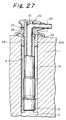
- FIG. 27 is a side view of a prior plug cap device, in which a main part of the device is shown in a cross sectional view.
- the prior plug cap device comprises an elongate cylindrical plug cap body 10 made of a synthetic resin and a rain cover 20 which constitutes a water-proof cover.
- the plug cap body 10 is provided with a rib 11 on the outer periphery of an upper end.
- a cylindrical ribber cap 12 is mounted on a lower end of the body 10.
- the rain cover 20 made of an elastic material is fitted on the upper end of the plug cap body 10 with the rib 11 on the body 10 being mated with an annular recess 22 formed on the inner periphery of an aperture 21 in the cover 20.
- a vent hole 23 is formed in an upper portion of a wall defining the aperture 21 in the cover 20.
- a groove 25 is formed in the inner periphery of the aperture 21 at positions from the vent hole 23 to the lower end of the rain cover 20.
- An air flow passage 24 is defined between the inner periphery of the groove 25 and the outer periphery of the plug cap body 10.
- An ignition cable 30 is inserted from the upper end of the rain cover 20 through a body of the cover 20 into the plug cap body 10.
- a discharge tube unit and a connecting terminal (not shown) connected to an end of the ignition cable 30 is received in a lower half portion of the plug cap body 10.
- the plug cap body 10 is inserted into a plug bore 2 in an engine body 1 and the connecting terminal received in the lower end of the plug cap body 10 is coupled together with a rubber cap 12 to a plug secured to an attaching portion 3 on the bottom of the plug bore 2. Further, a lower portion 20a of the rain cover 20 is airtightly engaged with an upper end of the plug bore 2, so that the rain cover 20 seals the plug bore 2 from an external area except the vent hole.
- a plug cap device comprising: a cylindrical plug cap body which can be detachably inserted into a plug bore extending vertically in an engine body; a water-proof elastic cover having a lower portion detachable and sealingly fitted in the upper end of the plug bore when the body is inserted into the plug bore, the cover having an aperture for receiving an upper portion of said plug cap body and a vent hole in a wall which defines the aperture; and an air flow passage formed between the plug cap body and said water-proof elastic cover so that when the body is disposed in the plug bore air in the plug bore can be discharged through the vent hole to an external area; a groove is formed in the outer periphery of said plug cap body so that said groove constitutes at least a part of said air flow passage.
- the air flow passage is constructed by the groove formed in the plug cap body, it is not necessary to form a groove for an air flow passage in the water-proof cover at the area of the groove formed in the plug cap body. Accordingly, it is possible to make the water-proof cover relatively thick which enhances the rigidity of the water-proof cover.
- a groove may be formed in the outer periphery of said plug cap body so that said groove constitutes at least a part of said air flow passage, and a recess may be formed on the outer periphery of said plug cap body so that said recess defines a water reservoir in an intermediate portion of said air flow passage.
- the air flow passage is formed from the groove formed in the plug cap body, it is not necessary to form a groove for an air flow passage in the water-proof cover at the area of the groove formed in the plug cap body. Accordingly, it is possible to make the water-proof cover relatively thick which enhances its rigidity. Also, since the water reservoir is formed from the recess formed in the outer periphery of the plug cap body at the intermediate portion of the air flow passage, high pressure air trapped in the plug bore is discharged through the air flow passage from the vent hole into an external area. On the other hand, water which enters from the vent hole into the passage is received in the water reservoir and is prevented from entering the plug bore.
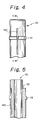
- FIGS. 1 through 5 show a first embodiment P1 of the plug cap device of the present invention.
- the plug cap device P1 comprises an elongate cylindrical plug cap body 110 made of a synthetic resin material and a rain cover 120 which constitutes a waterproof cover.
- the rain cover 120 is made of an elastic material to define a water-proof elastic cover.
- the rain cover 120 is provided with an aperture 121 which receives an upper end of the plug cap body 110.
- An annular recess 122 is formed on the inner periphery of the aperture 121.
- the rain cover 120 is provided with a vent hole 123 in a peripheral wall and with an umbrella-like grommet 125 on the outer periphery of the peripheral wall.
- the rain cover 120 is provided with an opening 124 through which an ignition cable 130 passes into the plug cap body 110.
- the plug cap body 110 is provided in an upper end with an opening 112 through which the ignition cable 130 is inserted and on the outer periphery of the upper end with an annular rib 113, a part of which is slotted to constitute a part of a groove 140 to be described hereinafter.
- the upper end of the plug cap body 110 is inserted into the aperture 121 of the rain cover 120 so that the rib 113 engages with the annular recess 122 in the rain cover 120.
- the groove 140 which constitutes an air flow passage is formed longitudinally on the outer periphery of the upper end of the plug cap body 110.
- the groove 140 extends from a position communicating with the vent hole 123 in the rain cover 120 to a position being below an lower end of the rain cover 120 and communicating with a plug bore 102 to be described hereinafter.
- An air flow passage 150 is defined between the inner surface of the groove 140 and the inner periphery of the aperture 121 in the rain cover 120.
- An end of the ignition cable 130 is inserted from the opening 124 in the rain cover 120 through the opening 112 in the plug cap body 110 into an upper half portion of the body 110.
- a discharge tube unit, a connecting terminal, and the like (not shown) connected to the end of the ignition cable 130 are received in a lower half portion of the plug cap body 110.
- a cylindrical rubber cap 111 is attached on a lower end of the plug cap body 110.
- the plug cap body 110 When the plug cap device P1 with the ignition cable 130 is assembled on an engine, as shown in FIG. 1, the plug cap body 110 is inserted into the plug bore 102 in an engine body 101 and the connecting terminal mounted on the lower end of the plug cap body 110 is coupled to a plug attached on a plug-mounting portion 103 on the bottom in the plug bore 102. Further, a lower portion 126 of the rain cover 120 is airtightly mated in an upper end of the plug bore 102 so that the grommet 125 of the rain cover 120 covers a peripheral area around the opening of the plug bore 102.
- the groove 140 is formed on the outer periphery of the plug cap body 110 and the groove 140 constitutes the air flow passage 150, it is not necessary to form the groove for the air flow passage in the rain cover 120 and it is possible to make the rain cover 120 relatively thick which enhances its rigidity.
- the thickness of the rain cover 120 does not become large and thus it is possible to form the air flow passage 150 with a size suitable for venting air.
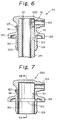
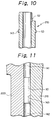
- FIGS. 6 through 11 show a second embodiment P2 of the plug cap device of the present invention.
- a rain cover 220 is provided on the inner periphery of the aperture 121 with a first groove 141 extending from the vent hole 123 to the annular recess 122 and with a second groove 142 extending from the annular recess 122 to the lower end of the rain cover 220.
- the annular rib 113 on a plug cap body 210 is provided with a notch or groove 143 between the first groove 141 and the second groove 142 so that the groove 143 communicates with the first and second grooves 141 and 142, thereby constituting an air flow passage 250 from the vent hole 123 to the plug bore 102.
- the groove 143 is formed in the rib 113 between the first and second grooves 141 and 142 so that the grooves 143 communicates with the first and second grooves 141 and 143 to form the air flow passage 250, as shown in FIG. 11, it is not necessary to form a groove for the air flow passage in the annular recess 122 and the wall around the annular recess 122 becomes relatively thick, thereby enhancing the rigidity of the rain cover 220.
- FIGS. 12 through 14 show a third embodiment P3 of the plug cap device of the present invention.
- the plug cap body 210 is provided with a water reservoir 260 on a half of the outer periphery at the position below an annular rib 213 to be described hereinafter and above a lower open end 227 of the rain cover 220. Further, the plug cap body 210 is provided on the outer periphery with a first groove 241 which extends downwardly along the axial direction from a position opposing to a vent hole 223 to the water reservoir 260. The plug cap body 210 is provided on the outer periphery except the first groove 241 with the annular rib 213 above the water reservoir 260.
- the rain cover 220 is provided with an annular recess 222 in opposition to the rib 213 on the inner periphery of the aperture 221 in the rain cover 220. Further, the rain cover 220 is provided with a second groove 242 on the inner periphery of the aperture 221. The second groove 242 extends along a fourth of the inner periphery of the aperture 221 in opposition to the water reservoir 260 below the annular recess 222 and turns downwardly and extends along the axial direction to the lower open end 227 of the rain cover 220.
- the first groove 241 in the plug cap body 210 is opposite to the vent hole 223 in the rain cover 220 at the upper end thereof while a peripheral end of the water reservoir 260 is opposite to an end of the second groove 242.
- the plug cap body 210 is mated with the aperture 221 in the rain cover 220 at the upper end thereof so that the rib 213 engages with the recess 222. Consequently, the second groove 242 communicates with the water reservoir 260 so that the air flow passage 250 is defined by these portions 241, 260, and 242.
- Water which enters from the vent hole 223 into the air flow passage 250 is received in the water reservoir 260 at the intermediate portion of the air flow passage 250, thereby preventing the water from entering into the plug bore. Further, the water received in the water reservoir 260 is vapoured by a rise in temperature in the plug bore and the vapour flow in a reverse manner in the air flow passage 250, so that the vapour is discharged from the vent hole 223 into the external area.
- the plug cap device if the first and second grooves 241 and 242, and the water reservoir 260 which constitute the air flow passage 250 are formed in both the plug cap body 210 and the rain cover 220, a total volume in the grooves and recess becomes large, a cross sectional area of the air flow passage 250 becomes large, thereby ensuring a good ventilation in the air flow passage 250 and increasing a capacity of the water reservoir 260, in comparison with the prior device having a rain cover in which the air flow passage is formed.
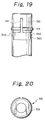
- FIGS. 15 through 18 show a fourth embodiment P4 of the plug cap device.
- a plug cap body 310 is provided with a water reservoir 360 on the outer periphery below an annular rib 313 to be described hereinafter and above a lower open end 327 of a rain cover.
- the water reservoir extends along a half of the outer periphery of the body 310.
- the plug cap body 310 is provided on the outer periphery with a first groove 341 extending along the axial direction from a position in opposition to a vent hole 323 to the water-reservoir 360 and a second groove 342 extending along a fourth of the periphery from an upper end of the water reservoir 360 and turning downwardly along the axial direction to the lower open end 327.
- the plug cap body 310 is provided on the outer periphery except the first groove 341 with the annular rib 313 above the water reservoir 360.
- the plug cap body 310 is inserted into the aperture 321 in the rain cover 320 with the first groove 341 in the plug cap body 310 being opposite to the vent hole 323 in the rain cover 320 and with the rib 313 being fitted in the recess 322.
- the vent hole 323 communicates with the lower open end 327 of the rain cover 320 through the air flow passage 350 which includes the first groove 341, the water reservoir 360, and the second groove 342.
- Water which enters from the vent hole 323 into the air flow passage 350 is received in the water reservoir 360, thereby preventing the water from entering into the plug bore.
- the water received in the water reservoir is vapoured due to a rise in temperature in the plug bore and the vapour flows in a reverse manner in the air flow passage 350, so that the vapour is discharged from the vent hole into the external area.
- the first and second grooves 341 and 342 and the water reservoir 360 which constitute the air flow passage 350 are formed in the plug cap body 310, it is not necessary to form a groove for the air flow passage in the rain cover 320 and the thickness of a wall around the annular recess 322 becomes large, thereby enhancing the rain cover 320 in rigidity.
- shapes of the air flow passages 150, 250, and 350 in the present invention are not limited to those shown in the above embodiments.
- the air flow passage 350 in the fourth embodiment is formed in the plug cap body 310, the passage 350 may take various shapes because the rain cover 320 is not subject to a limitation of thickness.
- the plug cap body 310 may be provided substantially on a half of the outer periphery below the rib 313 with the water reservoir 360.
- the first groove 341 is formed on the body 310 from a position opposite to the vent hole 323 to the water reservoir 360 while two second grooves 342 extend circumferentially from the opposite ends of the water reservoir 360, join together at the rear side, and turn downwardly at the joint point and extend to the lower open end of the rain cover, thereby defining the air flow passage 350.
- the second groove 342 may be branched at an intermediate portion of the first groove 341 so that the air flow passage 350 is formed.
- the second groove 342 may be formed from a middle portion of the water reservoir 360 to a rear side on the outer periphery of the plug cap body 310 so that the air flow passage is defined.
- the water reservoir 160 may be formed on the inner periphery of the aperture 121 in the rain cover 120 below the recess 122 and above the lower open end 127 of the aperture 121.
- first groove 141 is formed on the inner periphery of the aperture 121 so that the first groove extends longitudinally from the vent hole 123 through the recess 122 to the water reservoir 160.
- the second groove 142 may be formed on an area opposite to the first groove 141 on the inner periphery of the aperture 121 so that the second groove 142 extends longitudinally from the water reservoir 160 to the lower open end 127 of the rain cover 120.
- the plug cap device of the present invention since at least a part of the air flow passage is constructed by the groove formed in the plug cap body, it is not necessary to form a groove for an air flow passage in the water-proof cover at the area of the groove formed in the plug cap body, and consequently it is possible to make the water-proof cover relatively thick which can enhance in rigidity. Further, since the water reservoir is constructed by the recess formed in the outer periphery of the plug cap body at the intermediate portion of the air flow passage, a high pressure air trapped in the plug bore is discharged through the air flow passage from the vent hole into the external area. On the other hand, water which enters from the vent hole into the passage is received in the water reservoir and prevented from entering into the plug bore.
Landscapes
- Spark Plugs (AREA)
- Ignition Installations For Internal Combustion Engines (AREA)
Claims (9)
- Zündkerzenkappeneinrichtung (P1) umfassend:- einen zylinderförmigen Zündkerzenkappenkörper (110), der lösbar in eine Zündkerzenbohrung (102) eingeführt werden kann, die sich vertikal in einem Motorkörper (101) erstreckt;- eine wasserdichte, elastische Abdeckung (120) mit einem unteren Abschnitt (126), der lösbar und abdichtend in dem oberen Ende der Zündkerzenbohrung eingepaßt ist, wenn der Körper (110) in die Zündkerzenbohrung eingeführt ist, wobei die Abdeckung (120) eine Öffnung (121) zur Aufnahme eines oberen Abschnittes des Zündkerzenkappenkörpers (110) und ein Entlüftungsloch (123) in einer Wand besitzt, die die Öffnung (121) begrenzt; und- eine Strömungspassage (140) für Luft, die zwischen den Zündkerzenkappenkörpern (110) und der wasserdichten, elastischen Abdeckung (120) gebildet ist, so daß, wenn der Körper in der Zündkerzenbohrung eingeführt ist, Luft in der Zündkerzenbohrung (102) durch das Entlüftungsloch (123) zu einem äußeren Bereich abgeleitet werden kann;dadurch gekennzeichnet, daß
eine Nut (150) im äußeren Umfang des Zündkerzenkappenkörpers (110) gebildet ist, so daß die Nut zumindest einen Teil der Strömungspassage der Luft darstellt. - Zündkerzenkappeneinrichtung gemäß Anspruch 1, worin der Zündkerzenkappenkörper (110) mit einer Rippe (113) entlang des äußeren Umfangs desselben versehen ist, und die wasserdichte Abdeckung entlang des inneren Umfangs der Öffnung (121) mit einer Nut (122) versehen ist, die die Rippe aufnimmt; und worin der Zündkerzenkappenkörper auf dem äußeren Umfang desselben mit der Nut (150) versehen ist, die die Strömungspassage für Luft darstellt, wobei sich die Nut in Längsrichtung von einer Position gegenüber dem Entlüftungsloch (123) quer über die Rippe (113) zu einer Position unter einem unteren Ende des wasserdichten Körpers erstreckt.
- Zündkerzenkappeneinrichtung gemäß Anspruch 1, worin der Zündkerzenkappenkörper (110) mit einer Rippe (113) entlang des äußeren Umfanges desselben versehen ist, und die wasserdichte Abdeckung entlang des äußeren Umfanges der Öffnung (121) mit einer Nut (122) versehen ist, die die Rippe aufnimmt, worin die wasserdichte Abdeckung auf dem inneren Umfang der Öffnung (121) mit einer ersten Nut (141) versehen ist, die sich von dem Entlüftungsloch (123) zu der Nut (122) erstreckt, und mit einer zweiten Nut (142), die sich von der Nut (122) zum unteren Ende der wasserdichten Abdeckung erstreckt; und worin die Rippe (113) auf der Zündkerzenkappe mit einer dritten Nut (143) zwischen den ersten und zweiten Nuten (141, 142) versehen ist, so daß die dritte Nut (143) in Verbindung mit der ersten und zweiten Nut steht, wobei sich die Strömungspassage der Luft von dem Entlüftungsloch zu der Zündkerzenbohrung zusammensetzt.
- Zündkerzenkappeneinrichtung gemäß Anspruch 1, worin eine Nut (260) auf dem äußeren Umfang des Zündkerzenkappenkörpers gebildet ist, so daß die Nut ein Wasserreservoir in einem mittleren Abschnitt der Strömungspassage der Luft darstellt.
- Zündkerzenkappeneinrichtung gemäß Anspruch 4, worin der Zündkerzenkappenkörper (210) mit einer Rippe (213) entlang des äußeren Umfanges desselben versehen ist und die wasserdichte Abdeckung (220) entlang des inneren Umfanges der Öffnung mit einer Nut (222) versehen ist, die die Rippe aufnimmt, wobei der Zündkerzenkappenkörper mit dem Wasserreservoir (216) auf einer Hälfte des äußeren Umfanges unter der Rippe und über einem unteren offenen Ende der wasserdichten Abdeckung versehen ist; worin der Zündkerzenkappenkörper (210) ebenfalls auf dem äußeren Umfang mit einer ersten Nut (241) versehen ist, die sich nach unten in der axialen Richtung von einer Position gegenüberliegend dem Entlüftungsloch (223) zu dem Wasserreservoir (260) erstreckt; worin die wasserdichte Abdeckung mit einer zweiten Nut (242) auf dem inneren Umfang der Öffnung versehen ist; und worin der Zündkerzenkappenkörper mit der Öffnung in der wasserdichten Abdeckung an einem oberen Ende desselben so eingepaßt ist, daß die Rippe (213) in die Nut (222) eingreift und ein Umfangsende des Wasserreservoirs gegenüberliegend einem Ende der zweiten Nut (242) ist; wobei die zweite Nut in Verbindung mit dem Wasserreservoir steht, so daß die Strömungspassage für Luft durch die Nuten und das Reservoir zusammengesetzt ist.
- Zündkerzenkappeneinrichtung gemäß Anspruch 4, worin der Zündkerzenkappenkörper (310) mit einer Rippe (313) und entlang des äußeren Umfanges desselben versehen ist und die wasserdichte Abdeckung (320) entlang des inneren Umfanges der Öffnung mit einer Nut (322) versehen ist, die die Rippe aufnimmt, wobei der Zündkerzenkappenkörper mit dem Wasserreservoir (360) auf dem äußeren Umfang unter der Rippe und über dem unteren offenen Ende der Regenabdeckung versehen ist, worin das Wasserreservoir (360) sich entlang einer Hälfte des äußeren Umfanges des Körpers erstreckt; und worin der Zündkerzenkappenkörper auf dem äußeren Umfang mit einer ersten Nut (341) versehen ist, die sich entlang der axialen Richtung von einer gegenüberliegend dem Entlüftungsloch (323) liegenden Position zu dem Wasserreservoir erstreckt und mit einer zweiten Nut (342) versehen ist, die sich entlang eines Viertels des äußeren Umfanges von einem oberen Ende des Wasserreservoirs (360) erstreckt und nach unten entlang der axialen Richtung zu dem unteren offenen Ende der Regenabdeckung abgebogen ist, so daß die Strömungspassage für Luft durch die ersten und zweiten Nuten und das Wasserreservoir festgelegt ist.
- Zündkerzenkappeneinrichtung gemäß Anspruch 4, worin der Zündkerzenkappenkörper (310) mit einer Rippe (313) entlang dem äußeren Umfang desselben versehen ist und die wasserdichte Abdeckung (320) entlang des inneren Umfanges der Öffnung (321) mit einer Nut (322) versehen ist, die die Rippe aufnimmt, wobei der Zündkerzenkappenkörper (310) mit dem Wasserreservoir (316) auf einer Hälfte des äußeren Umfanges unter der Rippe versehen ist; worin eine erste Nut (341) auf dem Körper von einer Position gegenüberliegend dem Entlüftungsloch (323) zu dem Wasserreservoir (360) gebildet ist; und worin zwei zweite Nuten (342) sich bezüglich des Umfanges von den gegenüberliegenden Enden des Wasserreservoirs (360) erstrecken; sich auf der Rückseite des Zündkerzenkappenkörpers verbinden und am Verbindungspunkt nach unten abgebogen sind und sich zum unteren offenen Ende der Regenabdeckung erstrecken, so daß die Strömungspassage (350) der Luft durch die ersten und zweiten Nuten definiert ist.
- Zündkerzenkappeneinrichtung gemäß Anspruch 6, worin die zweite Nut (342) in einem mittleren Bereich der ersten Nut (341) abgezweigt ist, so daß die Strömungspassage der Luft gebildet wird.
- Zündkerzenkappeneinrichtung gemäß Anspruch 6, worin die zweite Nut (342) von einem mittleren Abschnitt des Wasserreservoirs (360) zu der Hinterseite auf dem äußeren Umfang des Zündkerzenkappenkörpers (310) gebildet ist, so daß die Strömungspassage der Luft definiert ist.
Applications Claiming Priority (4)
| Application Number | Priority Date | Filing Date | Title |
|---|---|---|---|
| JP5784992U JPH0615290U (ja) | 1992-07-23 | 1992-07-23 | プラグキャップ装置 |
| JP57849/92 | 1992-07-23 | ||
| JP1992063974U JP2595146Y2 (ja) | 1992-08-19 | 1992-08-19 | プラグキャップ装置 |
| JP63974/92 | 1992-08-19 |
Publications (2)
| Publication Number | Publication Date |
|---|---|
| EP0580295A1 EP0580295A1 (de) | 1994-01-26 |
| EP0580295B1 true EP0580295B1 (de) | 1995-11-02 |
Family
ID=26398939
Family Applications (1)
| Application Number | Title | Priority Date | Filing Date |
|---|---|---|---|
| EP93304919A Expired - Lifetime EP0580295B1 (de) | 1992-07-23 | 1993-06-23 | Zündkerzenkappevorrichtung |
Country Status (3)
| Country | Link |
|---|---|
| US (1) | US5377640A (de) |
| EP (1) | EP0580295B1 (de) |
| DE (1) | DE69300726T2 (de) |
Families Citing this family (9)
| Publication number | Priority date | Publication date | Assignee | Title |
|---|---|---|---|---|
| JP2602711Y2 (ja) * | 1993-10-13 | 2000-01-24 | 矢崎総業株式会社 | 点火プラグ取り付け孔のレインカバー |
| JPH0729792U (ja) * | 1993-11-01 | 1995-06-02 | 住友電装株式会社 | プラグキャップの空気抜き構造 |
| JP2914195B2 (ja) * | 1994-10-14 | 1999-06-28 | 住友電装株式会社 | 内燃機関のプラグキャップ |
| JPH08124651A (ja) * | 1994-10-24 | 1996-05-17 | Sumitomo Wiring Syst Ltd | 点火ケーブル用プラグキャップ |
| JP3145880B2 (ja) * | 1994-11-22 | 2001-03-12 | 住友電装株式会社 | 内燃機関用点火プラグと点火コイルの接続構造 |
| JP3361704B2 (ja) * | 1996-10-25 | 2003-01-07 | 矢崎総業株式会社 | 点火プラグ用プラグキャップ |
| US5799633A (en) * | 1997-08-08 | 1998-09-01 | Lexington Insulators | Electrical insulator with a duckbill-shaped valve |
| ES2283904T3 (es) * | 2003-06-04 | 2007-11-01 | GE JENBACHER GMBH & CO. OHG | Motor de combustion interna. |
| CN102971465A (zh) * | 2010-06-29 | 2013-03-13 | 沃尔沃建造设备有限公司 | 用于建筑机械驾驶室顶的防水垫圈 |
Family Cites Families (12)
| Publication number | Priority date | Publication date | Assignee | Title |
|---|---|---|---|---|
| US1748650A (en) * | 1929-06-28 | 1930-02-25 | Seiberling Latex Products Comp | Protective cover for ignition distributors |
| US2904769A (en) * | 1953-07-10 | 1959-09-15 | Gen Motors Corp | Spark plug nipple |
| US2835724A (en) * | 1953-12-21 | 1958-05-20 | Lee J Colbert | Sheathed electrical cables |
| US3545250A (en) * | 1968-10-03 | 1970-12-08 | George Curtis Jones | Body dent removing apparatus |
| JPS5819284Y2 (ja) * | 1977-07-18 | 1983-04-20 | トヨタ自動車株式会社 | ベンチレ−ションバルブ凍結防止用保温カバ− |
| US4723211A (en) * | 1984-08-30 | 1988-02-02 | International Business Machines Corp. | Editing of a superblock data structure |
| CA1281953C (en) * | 1984-09-27 | 1991-03-26 | Yoshiki Yano | Plug cap apparatus |
| FR2596589B1 (fr) * | 1986-03-25 | 1988-07-08 | Electricfil | Capuchon d'isolation pour bougie d'allumage de moteur a combustion interne |
| US4790767A (en) * | 1987-11-16 | 1988-12-13 | Prestolite Wire Corporation | Electrical connector for a distributorless ignition system |
| JPH04203269A (ja) * | 1990-11-29 | 1992-07-23 | Yazaki Corp | 高圧ケーブル装置 |
| US5154624A (en) * | 1991-09-13 | 1992-10-13 | Cooper Industries, Inc. | Ignition coil adapter for a distributorless ignition system |
| FR2682822B1 (fr) * | 1991-10-21 | 1994-01-21 | Sagem Allumage | Coiffe de connecteur de liaison pour cable electrique. |
-
1993
- 1993-06-21 US US08/078,645 patent/US5377640A/en not_active Expired - Fee Related
- 1993-06-23 EP EP93304919A patent/EP0580295B1/de not_active Expired - Lifetime
- 1993-06-23 DE DE69300726T patent/DE69300726T2/de not_active Expired - Fee Related
Also Published As
| Publication number | Publication date |
|---|---|
| US5377640A (en) | 1995-01-03 |
| DE69300726T2 (de) | 1996-04-11 |
| DE69300726D1 (de) | 1995-12-07 |
| EP0580295A1 (de) | 1994-01-26 |
Similar Documents
| Publication | Publication Date | Title |
|---|---|---|
| US5324207A (en) | Cap for a high-tension cable terminal for use in an automobile engine | |
| EP0580295B1 (de) | Zündkerzenkappevorrichtung | |
| US5811728A (en) | Waterproof rubber tap and waterproof connector | |
| US4495234A (en) | Weather strip for automobiles | |
| EP0549269B1 (de) | Wasserdichte Verbinder | |
| KR0148527B1 (ko) | 내연 기관용의 점화 플러그와 점화 코일을 연결하는 구조물 | |
| US4709123A (en) | Electric component for motor vehicles | |
| US5878706A (en) | Plug cap for ignition plug | |
| US5462023A (en) | Rain cover of an ignition plug attaching hole | |
| US5358415A (en) | Spark plug cap | |
| US5771870A (en) | Ignition coil for an internal combustion engine | |
| US4616758A (en) | Insulating container, in particular insulating bottle | |
| WO2021095453A1 (ja) | 電子装置 | |
| US4930050A (en) | Housing for automobile lamps | |
| US5755581A (en) | Plug cap for spark plug | |
| JP2595146Y2 (ja) | プラグキャップ装置 | |
| JPH0615290U (ja) | プラグキャップ装置 | |
| US5630721A (en) | Plug cord connecting structure | |
| CA2109894C (en) | Telescoping antenna device | |
| JPH0239220Y2 (de) | ||
| JP3954299B2 (ja) | 点火プラグ用プラグキャップ | |
| JP3389011B2 (ja) | 点火プラグ用プラグキャップ | |
| JPH0137321Y2 (de) | ||
| JPS6011732Y2 (ja) | 小型モ−タの防水構造 | |
| JP3361697B2 (ja) | 点火プラグ用プラグキャップ |
Legal Events
| Date | Code | Title | Description |
|---|---|---|---|
| PUAI | Public reference made under article 153(3) epc to a published international application that has entered the european phase |
Free format text: ORIGINAL CODE: 0009012 |
|
| 17P | Request for examination filed |
Effective date: 19930712 |
|
| AK | Designated contracting states |
Kind code of ref document: A1 Designated state(s): DE FR GB |
|
| 17Q | First examination report despatched |
Effective date: 19940414 |
|
| GRAA | (expected) grant |
Free format text: ORIGINAL CODE: 0009210 |
|
| AK | Designated contracting states |
Kind code of ref document: B1 Designated state(s): DE FR GB |
|
| REF | Corresponds to: |
Ref document number: 69300726 Country of ref document: DE Date of ref document: 19951207 |
|
| ET | Fr: translation filed | ||
| PLBE | No opposition filed within time limit |
Free format text: ORIGINAL CODE: 0009261 |
|
| STAA | Information on the status of an ep patent application or granted ep patent |
Free format text: STATUS: NO OPPOSITION FILED WITHIN TIME LIMIT |
|
| 26N | No opposition filed | ||
| PGFP | Annual fee paid to national office [announced via postgrant information from national office to epo] |
Ref country code: FR Payment date: 19990610 Year of fee payment: 7 |
|
| PGFP | Annual fee paid to national office [announced via postgrant information from national office to epo] |
Ref country code: GB Payment date: 19990623 Year of fee payment: 7 |
|
| PGFP | Annual fee paid to national office [announced via postgrant information from national office to epo] |
Ref country code: DE Payment date: 19990626 Year of fee payment: 7 |
|
| PG25 | Lapsed in a contracting state [announced via postgrant information from national office to epo] |
Ref country code: GB Free format text: LAPSE BECAUSE OF NON-PAYMENT OF DUE FEES Effective date: 20000623 |
|
| GBPC | Gb: european patent ceased through non-payment of renewal fee |
Effective date: 20000623 |
|
| PG25 | Lapsed in a contracting state [announced via postgrant information from national office to epo] |
Ref country code: FR Free format text: LAPSE BECAUSE OF NON-PAYMENT OF DUE FEES Effective date: 20010228 |
|
| REG | Reference to a national code |
Ref country code: FR Ref legal event code: ST |
|
| PG25 | Lapsed in a contracting state [announced via postgrant information from national office to epo] |
Ref country code: DE Free format text: LAPSE BECAUSE OF NON-PAYMENT OF DUE FEES Effective date: 20010403 |