EP0580397A2 - Konferenzgerät - Google Patents
Konferenzgerät Download PDFInfo
- Publication number
- EP0580397A2 EP0580397A2 EP93305681A EP93305681A EP0580397A2 EP 0580397 A2 EP0580397 A2 EP 0580397A2 EP 93305681 A EP93305681 A EP 93305681A EP 93305681 A EP93305681 A EP 93305681A EP 0580397 A2 EP0580397 A2 EP 0580397A2
- Authority
- EP
- European Patent Office
- Prior art keywords
- conference
- display
- data
- operative
- conference participant
- Prior art date
- Legal status (The legal status is an assumption and is not a legal conclusion. Google has not performed a legal analysis and makes no representation as to the accuracy of the status listed.)
- Withdrawn
Links
Images















Classifications
-
- H—ELECTRICITY
- H04—ELECTRIC COMMUNICATION TECHNIQUE
- H04M—TELEPHONIC COMMUNICATION
- H04M3/00—Automatic or semi-automatic exchanges
- H04M3/42—Systems providing special services or facilities to subscribers
- H04M3/56—Arrangements for connecting several subscribers to a common circuit, i.e. affording conference facilities
- H04M3/567—Multimedia conference systems
-
- H—ELECTRICITY
- H04—ELECTRIC COMMUNICATION TECHNIQUE
- H04M—TELEPHONIC COMMUNICATION
- H04M11/00—Telephonic communication systems specially adapted for combination with other electrical systems
- H04M11/06—Simultaneous speech and data transmission, e.g. telegraphic transmission over the same conductors
- H04M11/062—Simultaneous speech and data transmission, e.g. telegraphic transmission over the same conductors using different frequency bands for speech and other data
-
- H—ELECTRICITY
- H04—ELECTRIC COMMUNICATION TECHNIQUE
- H04M—TELEPHONIC COMMUNICATION
- H04M2203/00—Aspects of automatic or semi-automatic exchanges
- H04M2203/20—Aspects of automatic or semi-automatic exchanges related to features of supplementary services
- H04M2203/2061—Language aspects
-
- H—ELECTRICITY
- H04—ELECTRIC COMMUNICATION TECHNIQUE
- H04M—TELEPHONIC COMMUNICATION
- H04M2203/00—Aspects of automatic or semi-automatic exchanges
- H04M2203/50—Aspects of automatic or semi-automatic exchanges related to audio conference
- H04M2203/5036—Aspects of automatic or semi-automatic exchanges related to audio conference using conference for collection of feedback
-
- H—ELECTRICITY
- H04—ELECTRIC COMMUNICATION TECHNIQUE
- H04M—TELEPHONIC COMMUNICATION
- H04M3/00—Automatic or semi-automatic exchanges
- H04M3/42—Systems providing special services or facilities to subscribers
- H04M3/56—Arrangements for connecting several subscribers to a common circuit, i.e. affording conference facilities
- H04M3/563—User guidance or feature selection
- H04M3/564—User guidance or feature selection whereby the feature is a sub-conference
-
- H—ELECTRICITY
- H04—ELECTRIC COMMUNICATION TECHNIQUE
- H04M—TELEPHONIC COMMUNICATION
- H04M3/00—Automatic or semi-automatic exchanges
- H04M3/42—Systems providing special services or facilities to subscribers
- H04M3/56—Arrangements for connecting several subscribers to a common circuit, i.e. affording conference facilities
- H04M3/563—User guidance or feature selection
- H04M3/566—User guidance or feature selection relating to a participants right to speak
Definitions
- the present invention generally relates to conferencing apparatus, and in particular to conferencing apparatus for use during a conference that makes use of electronic communication means.
- the face to face meeting has historically been the primary mechanism used in all cultures to achieve consensus and to initiate and direct action. In such meetings, a number of practices are typically adopted to improve communication. Usually, an individual is selected to chair the meeting, managing its progress and, where the meeting is formal, determining who can speak. An individual may also be identified as the record keeper or secretary.
- the rules used to govern the conduct of the meeting may be formal or informal and include meeting management protocols, rules of interpersonal behavior and rules of verbal interaction. They govern communication between conference participants not only by speech, but also through facial expressions, body language and gestures and shared text and images.
- a further complication is that it is not possible to determine at any time who is in the conference. After an initial roll call, people may join the conference late, leave it, their connections may fail, or they may temporarily put the conference "on hold". Background noise is also a problem: unless participants mute their telephones when they are not speaking, the conference can be "flooded' with background sounds, including in some cases the music that is played when some telephones are put on hold.
- the conference service provider Darome Inc attempts to address this problem by having a trusted human operator monitor the voice conference equipped with the facility to mute disruptive connections. This service is labour intensive and so costly, and raises security issues.
- Video conferencing represents an improvement over voice conferencing, at higher cost. It uses special high speed digital connections. Currently, participants travel to special rooms and sit in a line facing a TV camera and monitors, sometimes with some means to create text on screen for joint review. Because of the linear layout, participants in the same room are forced to view each other through the TV system rather than directly. This artificial mode of interaction is not satisfactory for many meetings and participants. Also, without much confusing zooming of the camera, it is difficult to move rapidly from a review of participants' overall posture to a close study of their faces. In consequence, important information is lost. Video conferencing nevertheless represents an improvement on voice conferencing albeit at considerably higher cost.
- Meeting scheduling is facilitated by several existing products.
- Meeting Maker on the Apple (Trade Mark) personal computer (PC) operates over a local area network and provides a degree of automatic scheduling.
- Microsoft Windows (Trade Mark) for Workgroups allows users to manually schedule meetings using electronic mail over local and wide area networks.
- Meeting metaphor There is no known system that simulates a complete meeting metaphor including non-verbal components such as indications of comprehension, agreement with others in the meeting, requests to speak, or (current) presence or absence from the meeting.
- Conferenced Data Over Voice An important aspect of conferencing is to provide text and image information for participants while participants are speaking. An efficient way to be able to simultaneously transmit voice and non-voice information among the participants is to transmit both kinds of information over the same communication links. Existing systems partially satisfy this need.
- the Optel Communications, Inc. modem broadcasts data over a conferenced voice communication bridge.
- the present invention provides conferencing apparatus comprising display means visible to at least one conference participant, display driving means adapted to display conference parameters on said display means, and discrete input means operable by respective conference participants to modify variable said conference parameters displayed on said display means, said input means including reaction input means to input a signal that controls a displayed conference parameter that is indicative of a reaction of the respective conference participant to a conference event and for the displayed conference parameters.
- conference parameter is used in the specification to describe features of a conference which are openly true for all conference participants, and includes a) constant conference parameters that are constant for a particular conference, such as names of conference members, and b) variable conference parameters that can change during a conference such as reactions of conference participants to a conference event.
- the said display means comprises discrete displays for respective conference participants.
- the present invention also provides conferencing apparatus wherein at least one conference participant is located remotely and connected to the or each other conference participant by at least one communication channel, comprising display means including a discrete display for the or each remote conference participant; an associated respective display driver adapted to display conference parameters on a said display; discrete input means operable by respective conference participants to modify variable said conference parameters displayed on each said discrete display; modem means for the or each remote conference participant to provide data over voice modulation for the transmission and reception of data between the or each remote conference participant and other conference participants, said data defining at least modifications of said variable conference parameters.
- said conferencing apparatus includes automatic identification means to identify conference participants automatically and to control said display driving means to indicate said identities as conference parameters on said display means.
- the apparatus includes a respective voice detector for each conference participant, and automatic speaker identification means responsive to said voice detector to identify automatically the conference participant who is speaking and control said display driving means to identify said conference participant on said display means.
- the or each remote conference participant is connected by a single analogue telephone voice channel that is conveniently in turn connected to a multi-station conference bridge.
- the or each modem means is arranged to provide data over voice modulation on said single analogue telephone voice channel.
- Such data over voice modulation can be achieved by using a pre-selected band of the analogue telephone voice channel for data, whilst the rest of the bandwidth is used for speech.
- each modem means includes filter means operative to filter out the spectral portion of the voice signal to enable data transmission in said spectral portion, and to filter out received data in said spectral portion to enable clear voice reception at a receiving loudspeaker in a telephone handset for example.
- the remote conferencing apparatus includes discrete voice circuitry for the or each remote conference participant that includes a microphone.
- Dialogue control means is provided which is operable by a predetermined conference participant designated as a chairman to selectively disconnect the microphones of the conference participants. This allows a conference chairman to ensure that only a designated speaker is allowed to speak. This feature also reduces the level of background noise transmitted into the conference. Many conference participants who desire to speak can do so according to one embodiment of the present invention by using signaling means provided for the or each conference participant to enable the generation of a "request to speak" signal for transmission to the chairman.
- the remote conferencing apparatus includes control circuitry provided at the chairman's location that is operative to generate an acknowledgment signal for transmission to a conference participant from whom said request to speak signal is received.
- the display driver at the chairman's location then being operative in response to reception of the request to speak signal to display the identity of the conference participant from whom the request to speak signal originated.
- this queuing is carried out automatically, without the intervention of the chair.
- any participant can speak at any time and the system is restricted to displaying the identities of all current speakers.
- participants are identified on the display as iconic representations of faces.
- richer communication is provided between participants by identifying some or all participants by the display of previously input scanned photographs.
- the or each remote conference participant is further connected by a second communication channel for the transmission and reception of video images.
- the apparatus includes at each remote location video means to provide a video image of at least a speaking conference participant and video modem means to transmit and receive a video image to and from the or each remote conference participants.
- the display drivers in such an embodiment are adapted to display said video image on associated displays.
- the system includes one or more conference bridges: devices which allow all stations to intercommunicate. For telephone conferences, conference participants dial into (or are dialed by) a conference bridge or by conferencing service using such a bridge.
- the remote conferencing apparatus preferably includes clock means associated with the display means such that each discrete display has an associated discrete clock.
- the clock means is operative to count down from a preset conference time length and the display driving means is operative to display the count down on the display means. This gives a clear indication of the time left available on the telephone conferencing network for the present conference.
- the apparatus includes warning means operative in response to said clock means to cause said display driving means to display a warning when said count down reaches a preset value. This feature allows for a conference chairman to program the warning means to indicate when for instance the time allocated for discussing a particular motion has run out.
- the remote conferencing apparatus preferably includes keystroke and mouse movement means operative to capture and transmit a message in response to inputs from said input means.
- the display driving means is then operative to update on the display means both locally and for the other participants. This allows conference participants to use what can be termed a shared application.
- one embodiment of the present invention includes generating means operative to generate a text message in response to inputs from respective discrete input means operative by a conference participant.
- the text message is displayed by a respective display driver on an associated display.
- Message transmission means are provided that are operative to transmit said text message to one or more selected conference participants for display by a respective display driver on their associated displays only.
- this arrangement means can also be provided to indicate to all other conference participants that a message has been transmitted from one conference participant to one or more others.
- a means of ensuring message security is provided whereby encryption means are included within the system so that a select number of (one or more) conference participants can pass messages between or among themselves without other participants being able to read the messages.
- remote conferencing apparatus for use where at least one conference participant is located remotely and is connected to the or each other conference participant by a single analogue telephone voice channel.
- modem means arranged to provide data over voice modulation on said voice channel for transmitting or receiving data to or from other conference participants, a display, input means operative to generate data for display, processing means to control said modem means to transmit said generated data and to receive data for display generated remotely, and a display driver arranged to display said generated data and/or said receive data on said display.
- the processing means is responsive to control data to enable the input means to generate the data for display, or the processing means is responsive to a disabling signal to disable the input means from generating the data for display.
- the processing means is operative in response to an access demand signal from the input means to generate and transmit via said modem means a said disabling signal to the or each other conference participant and to enable said input means to generate said data for display.
- the data for display is text and cursor generating means that is provided to enable conference participants to indicate positions in the display text.
- a translator can be provided at a location to receive the text, translate it and re-transmit it to selected conference participants.
- remote conferencing apparatus comprises telephone apparatus for use when a plurality of telephone apparatuses are connected to each other by a single analogue telephone voice channels, said telephone apparatus comprising a microphone and remote mute means operable by a conference participant to selectively mute microphones of other telephone apparatuses being operated by the conference participants.
- Such muting can be provided by the transmission of a disabling signal that is responded to by respective microphones.
- conference participants can have a unique identification code.
- the machine used by the conference chairman is designated as the "Master Station" for the conference.
- the Master Station preferably contains circuitry to determine and or control the identification codes of the conference participants.
- Control circuitry at the location of each of the conference participants then being operative to compare a stored identification code with the identification code transmitted from the Master Station in order to generate a signal to identify that the conference participant is present.
- a present signal is transmitted in a time slot or poll sequence where the poll sequence corresponds to the sequence of the identification codes determined by the Master Station.
- the apparatus includes input means at each remote location operable by a conference participant to generate a request to speak signal to be transmitted to the Master Station.
- the control circuitry of the Master Station is able to identify from whom the request to speak signal originated and generate an acknowledgment signal.
- the identity of the speaker requesting to speak can be added to a queue and the position in the queue of that person can be displayed to conference participants.
- remote conferencing apparatus for use during the organizing of a conference between respective conference participants at remote locations connected together by a telephone channel, said apparatus comprising at each remote location a network connection to a public or private electronic mail network in the form of a local area network connection or a modem, memory means containing a diary for a prospective conference participant, input means for inputting information into said diary in said memory means and network connection control means responsive to said input means, network connection control means at a location being operative in response to a respective input means operable by a conference organizer to send mail to each prospective conference participant in turn to access respective diaries to determine a common date and time available for each prospective conference participant, and to make an entry temporarily in respective diaries if a common date and time is available, said input means at a prospective conference participant's location being operable by a prospective conference participant to generate an acceptance signal for transmission to the conference organizer; said network connection control means at the location of the conference organizer being operative to make a permanent entry in respective diaries if an acceptance signal is
- the network connection control means at the conference organizer's location is operative in response to respective input means to transmit an agenda for the proposed conference to each prospective conference participant when a temporary entry is made in each diary.
- the present invention also provides a method of improving communication between conference participants during a conference where at least one conference participant is at a remote location and is in audio or audio and video communication with the other conference participants using at least one common analogue telephone channel.
- the method comprises the repeated steps for the or each conference participant at a remote location, generating data representing conference parameters, said data being modifiable by a respective conference participant, transmitting said data using a telephone channel to the or each other conference participant, and receiving said data from the or each other conference participant, the transmitted and received conference parameters being displayed during transmission and reception.
- the present invention provides a low cost conferencing apparatus that allows conference participants to have available comprehensive information on the other conference participants and their interaction within the conference.
- the embodiments of the invention provide conferencing apparatus that allows for a designated chairman to be able to monitor and control the progress of a conference to more efficiently utilize conference time.
- conferencing apparatus allows for richer communication between conference participants who are communicating by telephone.
- Embodiments of the present invention overcome the limitations of previous systems that attempt to facilitate conferences using communications instead of physical meetings.
- a number of novel capabilities not previously known are included and a range of capabilities that have been provided previously in isolation are integrated.
- the apparatus conveniently provides an ability for individuals who may be located at diverse locations to interact more effectively than they would if they were meeting face to face at a single location.
- the embodiment of the present invention described hereinafter is a unique combination of special software and communications hardware that integrates a standard personal computer with a single standard telephone line and standard conference bridges.
- the invention also optionally uses local area network or other communication facilities with suitable bridging capability.
- the embodiment of the invention includes a voice (and optionally video) conferencing capability that is enhanced by a unique data conferencing capability wherein each conference participant can be guaranteed that the participant can send data to and receive data from every other participant, at will, within one second.
- Each station within a conference consists of a conventional telephone (with or without a video camera) and a standard personal computer that are connected together using the hardware of this invention.
- the connections use conventional telephone (or video) conferencing techniques or services.
- To this arrangement is added the capability of sending data simultaneously with the voice (or video) transmissions.
- the data transmission(s) are controlled in a unique manner using a "round-robin" concept whereby each participant is allowed to send data to every other participant in turn.
- Such data can range from brief reactions to conference speakers by participants, to factual (textual or graphical) information which one participant makes available to one or more other participants (a "caucus" feature).
- the software of the embodiment of the invention provides a "meeting metaphor".
- This capability includes alternate graphical representations of a meeting room in which conference participants are assigned physical locations and unique identities. Users employ this display for a number of useful purposes. For example, it clearly identifies the current speaker. It further allows participants to signify their desire to speak. Non-verbal feedback is made available to the current speaker (including the degree of comprehension and agreement of both individuals and the group as a whole.) Using the metaphor, the system shows when a specific individual leaves or joins the conference.
- a number of options are included by which participants may signal their desire to speak. These range from a "free for all” where participants contend for recognition by the others to a "first come first served" protocol.
- a conference can be controlled by a conference chairman so that a participant can only speak when he is recognized by the chairman. Participants can at any time interrupt the current speaker on a point of order or point of information or for any other reason.
- the participants are shown grouped around a common work area on which such items as the meeting agenda and specific items of information can be posted.
- This area can be used as a conventional whiteboard to which any participant can write textual and graphical information using their computer keyboard and pointing device.
- the area can also be used to run applications such as spreadsheets jointly on the machines of all participants.
- the embodiment of the invention includes a number of features that enhance the management of a conference.
- the software allows for allocating specific amounts of time to each agenda item, tracking the amount of time actually taken on each item, and allowing participants to observe the expected time at which the current agenda item or the conference will conclude.
- the software allows either the chairman, or a designated conference secretary, to keep minutes of the meeting as it progresses and to allow participants to review them as they are generated.
- a chairman can call for votes on specific decision items.
- the system records the votes and makes the results available to the participants.
- the software allows individual participants to pass notes and other information to one or more specifically designated recipients. Recipients can be designated during the conference by the person generating the note, or they can be identified as a group prior to convening the conference. In this manner, the system supports the idea of forming one or more "caucuses", sub-groups of the entire meeting. This capability allows, for example, members of one organization involved in a negotiation with another organization to reach a consensus position privately that can then be presented to the other organization.
- the software also includes meeting planning and scheduling capability. This allows coordination of the schedules of proposed meeting participants, who may be in different time zones, and the distribution (electronically) of relevant material (including material generated at prior conferences) before convening the conference itself.
- the system simplifies the following up of action items that result from a conference.
- This meeting set-up and follow-up capability uses available private or public electronic mail services for data transfer.
- the system is designed to enable users who are not "computer literate" to use it effectively without a long learning period.
- a user can exploit most features of the system using only a pointing device such as a computer mouse or pen.
- the system supports use of a keyboard as an input device for composing and sending notes, writing on the whiteboard and so on in a manner that requires only limited keyboard skills.
- Figs. 1A and 1B illustrate remote conferencing apparatus for use during a voice/data conference (Fig. 1A) or a video/voice/data conference (Fig. 1B) wherein at least one conference participant is located at a remote location and is in communication with the other conference participants by a single telephone voice channel, i.e. a single Public Switched Telephone Network (PSTN) line, or communication media suitable for voice or voice and video transmission.
- PSTN Public Switched Telephone Network
- the apparatus comprises a computer 1 such as an IBM (Trade Mark) compatible personal computer.
- IBM Trade Mark
- a Voice/Data Modem card 2 is fitted inside the computer 1 within a standard expansion slot for connection to a single PSTN line 6 and, in turn to a standard termination 3.
- the apparatus also includes a telephone handset 4 that is connected to the Voice/Data Modem 2 by line 5 and thereby also connected through the Voice/Data Modem to line 6 and thence to termination 3 of the single PSTN line.
- the computer 1 includes a display 7 and a keyboard 8. Also a mouse pointing device, or equivalent, (not shown) is included.
- the telephone handset 4 is provided with the normal features of a such a device and might include a "speaker-phone" capability so that a conferee is able to participate in a voice/data conference without holding a telephone handset to his ear.
- the computer 1 is also able to transmit data over the PSTN line in a conventional mode where the Voice/Data Modem 2 takes control of the PSTN line and uses the full bandwidth of the single telephone voice channel.
- the Voice/Data Modem 2 takes control of the PSTN line and uses the full bandwidth of the single telephone voice channel.
- the data When data transmission takes place simultaneously with speech transmission, the data must occupy a much smaller bandwidth in order to share the total bandwidth of the single telephone channel with voice transmission.
- Fig. 1B shows components added to provide video as well as voice/data conferencing.
- a camera 9 is shown that will capture a conferee's image for transmission to remote members of a conference.
- Fig. 1B shows as an alternative a microphone 10 and a loudspeaker 11.
- a second card 13 is included along with an Voice/Data Modem card 2.
- This second card is a video modem. It is shown connected to a second PSTN line 13 in addition to a line for voice transmission 12.
- the cards shown could encode voice and video inputs to provide a digital output connected to a single transmission facility capable of multiplexing both voice and video signals.
- ISDN Integrated Service Digital Network
- LAN Local Area Network
- Ethernet or Token Ring systems or a combination of these facilities along with the PSTN or wide band private line circuits.
- the Voice/Data Modem 2 shown in Fig. 1B is assumed to be similar to the one shown in Fig. 1A.
- the video portion of the system can be any of a number of standard variations that can be integrated with the voice/data modem capability of the invention by one skilled in the art.
- Fig. 2 is a block diagram of the construction of the voice/data embodiment illustrated in Fig. 1A. Shown in Fig. 2 is the computer 1 that contains the plug-in Voice/Data Modem 2. Data generated within or displayed on the computer is passed to or from the plug-in Voice/Data Modem 2. Connected to the Voice/Data Modem through line 5 is a standard telephone set 4. Also connected to the Voice/Data Modem 2 is an output line 6 that in turn is connected to the PSTN termination 3.
- Fig. 3 is a block diagram of the preferred embodiment of the Voice/Data Modem 2 which makes use of standard Digital Signal Processor (DSP) technology. Shown are the transmitter (sending) portion of the Voice/Data Modem in the upper portion of the figure and the receiver in the lower portion.
- a Clock circuit 20 provides a timing reference for both transmitter and receiver blocks of the Voice/Data Modem.
- the basic timing rate of the system is preferably 8,000 Hz, the international standard sampling rate for digital voice transmission and switching systems.
- each voice sample is a 12-bit or 13-bit quantity.
- the North American Standard is 12 bits for conversion to an 8-bit quantity using ⁇ -log compression standard. In Europe, 13-bit quantization is used for conversion to the A-log 8-bit compression standard of the CCITT.
- the voice signal 5 (preferably from a telephone set) is connected over a 2-wire line (or, alternatively, the sender portion of a 4-wire connection) to an analogue to digital converter (A/D Converter) 21.
- the analogue telephone signal is converted to 12 bits digital samples in accordance with standard telephone practice.
- the output from the A/D Converter 21 is connected to a digital Low Pass Filter 22 that is preferably implemented as a part of a DSP. Assuming that the data portion of the signal is centered at a frequency of preferably 3000 Hz and that the nominal (Nyquist rate) bandwidth is preferably 300 Hz, the digital filter is implemented as a sharp cut-off filter.
- the filter is implemented with a raised cosine spectral characteristic and has a 3 dB cut-off frequency of 2700 Hz and an attenuation of 20 dB.
- the filter can be implemented as a multi-pole Butterworth or elliptical pass band characteristic.
- the data transmitter portion of the Voice/Data Modem accepts data from an 8-bit bus 29 that is stored in a Data Buffer 30 with sufficient storage to facilitate implementation of the data protocol described below.
- the amount of storage is preferably 512 bytes (4,096 bits).
- Data are read into the buffer in 8-bit bytes and are read out serially by bit into the Data Modulator 27.
- Data are read out of the Data Buffer 30 under the control of the Data Start Line 31 and an output from the Clock Module 20 (not shown explicitly).
- An enabling signal on the Data Start Line begins the transfer of a block of data stored in the Data Buffer where said enabling signal is generated by timing logic within the Computer 1 and the Clock Module.
- the Data Modulator 27 is implemented in the DSP using a standard modulation technique, preferably a standard 8 level quadrature amplitude modulation (QAM) algorithm.
- the preferable encoded bit rate is 600 bits per second. Since the 8 level modulation technique encodes 3 bits in a modulation symbol, the rate at which symbols are sent (the baud rate) is 200 symbols per second, resulting in a data signal bandwidth of roughly three times the Nyquist bandwidth, or 600 Hz.
- the output of the Data Modulator 27 is connected to the digital Adder 25 where said output is transferred at the system sampling rate of preferably 8000 Hz. These samples are summed (linearly) by the Adder, the output of which is connected to the D/A Converter 21 as described above. Using this arrangement, both voice and data are transmitted simultaneously through the Hybrid Junction 28 and over the PSTN line 6.
- Low Pass Filter 34 eliminates the data signal energy from the voice signal. It has a 3 dB bandwidth equal to that of the Low Pass Filter in the transmitter.
- the output of the High Pass Filter 34 is connected to the D/A Converter 32 to provide an analogue output signal to the telephone over line 5, that is either a 2-wire line or the receiver pair of a 4-wire connection. Note that the transmitter and receiver filters are in tandem resulting in a 6 dB voice bandwidth of 2700 Hz for the end-to-end system.
- a High Pass Filter 35 is designed with a 3 dB bandwidth of approximately 2,700 Hz. Its purpose is to eliminate voice signal energy from the data path.
- the output of the High Pass Filter is connected to a Data Demodulator 37 that implements within the DSP the inverse process to that implemented in the Data Modulator 27.
- the output of the Data Demodulator is a serial bit stream that is stored in the Output Data Buffer 39 whose output 40 consists of an 8-bit bus.
- the Data Demodulator produces a Signal Present signal on line 43 within computer 1 of Figs. 1 and 2.
- the serial data produces an output on the Serial Data line 41 and a clocking signal aligned with the data appears on the Data Clock line 42. These signals are used by the computer for timing and data acquisition purposes.
- the DSP is a programmable device that is connected preferably to a 16-bit Data Bus 26. As shown in Fig. 3, this bus is connected to Low Pass Filters 22 and 34, to High Pass Filter 35, to Data Modulator 27, to the Data Demodulator 37 and to the Clock 20.
- This arrangement allows for changes in the operation of the system to introduce embodiments other than the preferred embodiment.
- it allows the Voice/Data Modem to be programmed to operate in a data only mode. In this case, the bandwidth of Low Pass Filter 22 is set to zero so that no voice energy is allowed to enter or leave the system. In this mode, the entire available bandwidth of the voice channel is available for data transmission.
- Appropriate software is also loaded into the other filters, the modulator and demodulator along with appropriate clock signals.
- Fig. 4A, 4B and 4C Characteristic physical configurations of stations are shown in Fig. 4A, 4B and 4C. Shown in Fig. 4A is a multiplicity of stations, each connected to a single point that is the summing junction 45 of a multi-party conference.
- Fig. 4B shows a group of stations connected in a ring configuration where each station is connected to the same transmission facility in a serial manner.
- Fig. 4C shows a multidrop configuration where all stations are connected to a common communication facility. These latter configurations are typically used in local area networks and in multi-station radio systems (such as the Aloha system) and other wide area network systems.
- the conference bridge of Fig. 4A is the preferred embodiment.
- the Conference Bridge 45 assumed is one conventionally used for voice.
- data transmission utilizes only a small bandwidth of the single telephone voice channel, data transmission is restricted, for example to 600 bits per second. It is important that the displays at the locations of the conference participants are updated frequently in order to facilitate the rapid interaction that occurs during a conference. It has been found to be necessary for all participants in a conference to receive data from every member of the conference at least once every second.
- Timing delays must be considered when designing a data protocol that provides for this rapid interaction over a conference bridge.
- each station connected in any of the "multipoint" configurations of Fig. 4A, 4B and 4C, and specifically to a Conference Bridge must obey a specific set of rules, i.e., a well-defined protocol.
- the embodiment of the present invention extends past practice by making use of a unique characteristic of a conference bridge, namely, that such a bridge contains a " s umming junction" where signals from all active stations are added to one another for transmission to all stations.
- the uniqueness of the configuration of Fig. 4A is that transmissions from all stations to all other stations pass through a single point. As a result, any station receives signals from all other stations in the same order that they appear at the summing junction of the conference bridge.
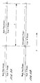
- Fig. 5 There are two modes of data transfer. These are illustrated in Fig. 5. "Basic Data Frames” allow each station in the system to transfer certain elemental data to all other stations once each frame interval. "Information Data Frames” allow a single station to transmit an extended amount of information to either all other stations, or selectively, to a subset of the stations. These two modes of transfer as well as two other modes used for initial station connection and for error control are under the control of the Master Station and of the rules of the protocol. The other two modes are the Acquisition Data and Error Modes that are used to allow new stations to become connected to a conference and to facilitate error recovery when abnormal circumstances occur.
- C/R-R/R Blocks include the Master Station Command/Response Data Block that occurs at the beginning of every frame and the Slave Station Request/Response Data Blocks.
- C/R-R/R Blocks are all data blocks included in the system other than Information Data Blocks used in Information Data Frames.
- C/R-R/R Blocks can communicate status information as a part of their purpose.
- Information Data Blocks are meant to transfer larger amounts of information among the stations and are associated with Information Data Frames defined above.
- the preferred embodiment is an automatic method of assigning stations as they become connected contains the following sequence of operations:
- Each station responds in inverse order of its Station ID Code (assumed assigned in order at the time of initial connection).
- Using a Consequent Response protocol either fixed or variable frame periods may be used. It is simpler to use variable periods and that approach is assumed in the following.
- Each Slave Station begins transmission of its Slave Station Request/Response Data Block immediately after it receives the end of the transmission of the data block from its predecessor station.
- the Slave Station at the start of the round robin sequence begins transmission after it has received the Master Station Command/Response Data Block.
- the next in sequence begins transmission after it has received the Slave Station Request/Response Data Block from the previous Slave Station, and so on.
- the process continues until the Master Station receives the Slave Station Request/Response Data Block from the final Slave Station in the sequence. At that time, the Master Station initiates another Basic Data Frame cycle, or changes the system mode to one of the other modes described.
- the Master Station can monitor the progress of the Basic Data Frame process. If it determines that a station is not responding to its predecessor within a time which is less than twice the maximum delay, the Master Station supplies a surrogate Slave Station Request/Response Data Block for the Slave Station that is not responding to its poll. This operation keeps the cycle going.
- the Master Station After having sent its surrogate Slave Station Request/Response Data Block, waits for the maximum delay period, and not hearing a response from said data block's successor, sends another surrogate Slave Station Request/Response Data Block using as the Station ID Code said successor's Station ID Code. This process continues until a Slave Station that remains responds to a surrogate Slave Station Request/Response Data Block.
- the total period required from the time the first Basic Data Block is transmitted from any station and the time that the Master Station Command/Response Data Block has been received at the most distant station is equal to the delay from the nth Station block to the Conference Bridge, plus the round trip delay from every other station to the Conference Bridge plus the delay from the Conference Bridge to the most distant station.
- ⁇ i is the delay between Station #k and the Conference Bridge
- the total length is 1.153 seconds.
- propagation delays are approximately equal to the length of all transmissions.
- Basic Data Frames As described above, there are two system modes that determine the types of transmissions being sent, Basic Data Frames or Information Data Frames as shown in Fig. 5.
- Basic Data Frame mode all stations send their basic data according to the chosen protocol.
- Information Data Frame mode only one station is transmitting information. It is one of the functions of the Master Station to set the mode of the system and to determine that all stations are in the correct mode.
- the preferred embodiment of the system makes use of Digital Signal Processors (DSPs) for generation and detection of data blocks.
- DSPs Digital Signal Processors
- the transmission system is assumed to be the analogue telephone network.
- the information being sent is converted from digital to analogue for transmission and back to digital for reception using universally available digital communication components.
- the duration of each data frame is seconds. Its default value is set for a given system release, but can be changed after shipment.
- a granularity unit is determined from the system clock by the granularity unit divisor N G that determines the minimum time for a particular embodiment of the system for which decisions are made concerning data communicated among the stations.
- each baud period chosen for the system be an integer number of samples and an integer number of carrier cycles.
- each symbol chosen for the system can be a fixed set of sample amplitudes that include both carrier and data information. Data recovery by the receivers in the system is facilitated by this choice. Intersymbol interference is more easily controlled and acquisition of carrier phase at each receiver is simplified.
- the baud period is chosen to be an integer multiple of 3 carrier cycles (samples), that is, a multiple of 1 msec.
- the Nyquist bandwidth is the minimum bandwidth required to transmit at the information rate with the number of bits per symbol shown. Practical systems require bandwidths larger than this rate. If the chosen baud period is 5 msec and the number of bits per symbol is 3, the data rate for this combination is 600 bits per second. The Nyquist bandwidth is 200 Hz; a practical bandwidth is of the order of 600 Hz.
- the length of any data block transmitted from any station must be an integer number of baud periods.
- each data block is a multiple of 3 bits.
- the throughput of the system can be maximized by judicious choices for the structure of data blocks used in the system.
- the number of bits required in each data frame along with a brief description of each field is given in Tables 3 and 4 in the Appendix.
- each frame begins with a Space that is preferably a single baud period in length that is meant to allow for acquisition of the data signal by a conference bridge, and allows the demodulators in each station to acquire carrier lock of the signal.
- the time required is more than one baud period; this can have an adverse impact on system performance by increasing overall system delays.
- the Space is preferably a period where a fixed symbol is sent. This allows a conference bridge to detect the presence of a signal at the time a predecessor block ends and to connect a new signal to the summing junction. In performing this action, some conference bridges clip off the first few milliseconds of a new signal in detecting its presence. For example, if the baud period is 5 msec and the detection (clipping) period of the bridge is 4 msec, all but 1 msec of the Space period would not appear at the summing junction and would not be received by any of the stations. (Alternatively, the Space period could be a period where no energy is present, providing a gap between data blocks. However, this approach would not work where the number of conference participants exceeds the maximum simultaneously connected capacity of the conference bridge and where the conference bridge clips off the first part of a signal.)
- the Master Station always sends a Master Station Command/Response Data Block at the beginning of each frame that is identical in length, but whose content depends on the mode of the system. This is true even if the Master Station is to send an Information Data Block. In this case the Information Data Block is preceded by a Master Station Command/Response Data Block. Tables 3A and 3B show an illustrative case of Master Station Command/Response Data Block fields.
- Table 3A shows the field state alternatives for a Master Station Command/Response Data Block for all fields except Field 4, the Command/Status Field. It is detailed for the various System Modes (Field 5) in Tables 5 and 6.
- Every data block of the system begins with a Field 1 that is a Space. It is used for system synchronization as described above.
- Field 2 is the "window" field that is the Frame Address for use in the error control means described below.
- Each frame is given a consecutive address of 0, 1, 2, or 3 in an ever recurring cycle as long as there is no error.
- the error control means causes the system to revert to a previous address state when an error is detected.
- Field 3 is the Station Address that is used in conjunction with the Command/Status Field. It is a 5-bit field used to address either individual stations or pre-defined groups of stations. It may designate various subsets of stations that are user-determined either prior to, or during a conference and include, as a minimum, "all stations" which is designated as Station ID Code 0.
- Field 4 a 5-bit field, is the Command/Status Field. Taken together with the station address field, status information is sent from one station to other stations. In addition, the Slave Stations send requests to the Master Station for permission to speak (voice) or send a data frame to the addressed station(s). The Master Station sends commands to either individual stations or groups of stations as designated by the address field.
- Slave Station Request/Response Data Blocks depends on the mode of the system and the communication protocol being used.
- the Master Station either continually, or periodically sends Master Station Command/Response Data Blocks that command the system to be in the Acquisition Mode so that new Slave Stations can become connected to the conference.
- Master Station is connected alone to the Conference Bridge, Acquisition Mode Master Station Command/Response Data Blocks are sent continuously. After one or more Slave Stations are connected, the Master Station signals the Acquisition Mode only periodically.
- the system is set into the Acquisition Mode when the Master Station Command/Response Data Block sends a block with Field 5 set to the ⁇ acquisition > state, i.e., state 0.
- Table 4 shows Slave Station Request/Response Data Block fields for this case.
- the data block consists of only a Space field and a Temporary Station ID field.
- An additional bit, labeled Request/Response is required to inform the Master Station whether the Slave Station is requesting connection to the conference, or is responding to a specific poll from the Master Station during the connection sequence.
- the total block length is 9 bits or 15 msec. This length is purposely shorter than that for the other modes to minimize the probability that transmission from multiple new stations will collide.
- Table 5 shows the Slave Station Request/Response Data Block for Basic Data Mode Frames. It is identical to the Master Station Data Block shown in Table 3 with three exceptions.
- Field 4 is replaced by a Status/Request field which is 5-bits in length.
- Field 5 becomes a Station ID Code field which designates the address of the sending station, i.e., the Slave Station sending the block.
- Field 6 is replaced by a Spare field which is non-zero bits in length when the sum of the bits assigned to the other fields is not evenly divisible by the number of bits per baud period.
- the error control means (described below) does not require an error control field in any block except the Master Station Command/Response Data Block.
- the following discloses the Master Station Command/Status and Slave Station Status/Request Fields used to define operational states of the invention.
- Table 6 shows the various Command/Status Field states for the described protocol when the system is set in the Acquisition Mode. The use of these fields has been described under the protocol descriptions presented in connection with a description of Fig. 6 above.
- Table 7 lists the set of states that can be signaled by both Master and Slave Stations in the current implementation. Additional states will be added as features are added. Each state listed is either a command, a request or a status indication. States that can be signaled by the Master Station are designated by an "M"; those signaled by a Slave Station by an "S”; and those that can signaled by either by an "MS".
- All states signaled are used within the system as "latches". In other word, the states are assumed to be in effect until changed by a succeeding transmission of a countermanding state. All stations either generate a state message for itself or can hear all state messages from all other stations. Software in each station maintains the state signaled by all other stations. In addition, the Master Station periodically sends Information Data Blocks addressed to Slave Stations that contain state information of every connected station. These Information Data Blocks are used by all Slave Stations to synchronize their stored state tables to synchronize them with those recorded by the Master Station. Any discrepancies found by a Slave Station of its state information triggers that station to send appropriate Basic Data Block(s) to correct the error. Although such errors are unlikely to occur, this mechanism assures robustness of the system in the event of pathological conditions.
- the Master Station Whenever the Master Station detects a Cyclic Redundancy Checksum (CRC) error in a frame or when it receives an ⁇ error_detected > status indication from any Slave Station, it places the system into Error Mode.
- CRC Cyclic Redundancy Checksum
- the Master Station sends a Reset Command that consists of the appropriate Window address and a Command/Status field set to the 0 state. In response to this command, all stations revert to the state prior to the sending of said Window address frame and resume operation from that point.
- the format for Information Data Blocks is the same whether sent by the Master Station or a Slave Station. Its structure is shown in Table 8. As with all data blocks, it begins with Space, Window and Station Address fields. As usual, the Station Address field designates the station or group of stations to which the message is intended and the Station ID Code is the address of the station sending the message. The Message Type field defines the intended use of the message. Its alternatives are shown in Table 9. The message lengths shown assume that a data compression algorithm (such as ZIP format compression) is used to minimize field lengths. These values are expected values rather than maxima.
- a data compression algorithm such as ZIP format compression
- the message itself follows and is limited in length by an arbitrary bound set for the system. Whenever the message length exceeds the maximum for a given frame, it extends over multiple Information Data Frames. Once permission to send an Information Data Block is given by the Master Station, that is, the system is put into the Information Data Mode, the Master Station can continue to keep the system in that mode by sending additional Information Data Mode signals, or intersperse the frames with Frames in other modes. Table 9 lists current data block types: this will be extended as features are added.
- the Conference Bridge itself has parameters that affect overall system operation. Most, if not all, conference bridges with more than a small number of ports operate in a way where only a subset of the total number of stations connected to a conference are physically connected to the summing junction of the bridge at the same time. This approach is necessary to reduce noise heard by participants and to assure that too many people are not trying to speak at the same time. There are five critical parameters that affect operation of systems based on embodiments of the invention. These are listed in Table 10 in the Appendix. These characteristics of a conference bridge affect the permissible design of data blocks used. Both the final design and the operation of a system depend on determination of these parameters for specific embodiments.
- Error control is an important aspect of the system. It is critical that each station attached to the system be operating in the same mode and that a mechanism be provided for resetting the entire system in case of pathological error conditions. It is also important that a mechanism be provided for detection of errors that occur and to provide for retransmission of frames contaminated by errors.
- a unique error control method is described for providing a robust method of error control as a part of one embodiment of the invention that minimizes the amount of bandwidth that must be provided.
- an error control technique used for asynchronous low speed transmission is to append a "parity bit" to a block of data.
- This method of error detection is useful if two conditions obtain: first, if the probability of error for each bit in a block is independent of every other bit in the block, and second, if the probability of error is low. In the system, the second condition is expected to occur in most conferences.
- the first condition is not valid. Noise within the telephone network occurs primarily as noise bursts rather than noise related solely to the bandwidth of the signal channel. Thus, when noise occurs, it is likely to influence more than a single bit time.
- the Master Station sends the CRC sum pattern that it has computed to all other connected stations. These stations each compare this pattern as received from the Master Station with the one that it computed locally. If they match, no action is taken. If they are different, one or more Slave Stations have determined that an error has occurred and in its next available time slot of a Basic Data Frame, each sends an "Error Detected" command along with the Window Address received by the Slave Station from the Master Station in its data block that contained the CRC sum used in the comparison.
- the Window Address field must be included since Basic Data and Information Data Frames can be intermixed.
- the Master Station must be able to reset the system to the Window Address state where the error occurred. As shown previously in the invention description, it is necessary to reset the Window Address to the last Basic Data Frame Window Address if an error occurs in an Information Data Frame.
- Using a 2-bit Window Address field allows for more than a single Information Data Frame to follow another, an important element in maximizing information flow through the system. It is not always necessary for a Slave Station to send an Error Detected command when an error occurs.
- the system operates by using the window type of operation wherein a mouse is used to move a cursor to within a window whereupon the mouse button is clicked to select that option.
- the following describes the software at its first release, as implemented on Microsoft Windows (Trade Mark) version 3.1.
- the top row of buttons is used to invoke the different functions of the system.
- the second row of buttons is used to identify the Groups to which the user belongs: Groups provide a context to the functions selected by the top row of buttons.
- At the top right of the screen are a clock and date display.
- the PCs communicate using electronic mail through a network connector attached to the PC which can be a modem or a Local Area Network adapter.
- Help When the Help option is selected, the selection of another option provides 'Help' text for that command. Help can also be used to report a problem to the administrator of the system.
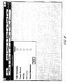
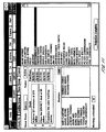
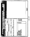
- Selecting Admin is only possible for the systems administrator nominated to support the users of the system. Selecting the option gives the display shown in Figure 8. The Faults Outstanding selection allows the systems administrator to monitor and reply to faults reported by users.
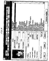
- Change Directory allows the administrator to modify the contents of a list of users who are connectable using the system, as shown in Figure 9.
- a user in the list is identified by name and their preferred language (English, French, German, Italian, Japanese for example) can be indicated together with their telephone country code and operating system utilized by their computers. This feature allows the system to organize conferences between users with different systems software.
- a systems administrator is also able to change the administrator, i.e. pass the system administration on to another user. This is achieved using the Change Administrator function.
- a group is a selection from the user Directory of a set of individuals who are working to a common goal.
- An individual may be a member of up to 6 groups.
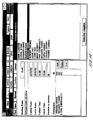
- the Group option allows a user to create a new group, to modify the description of a group which they have previously created, or to review the description of a group of which they are a member.
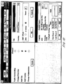
- Figure 11 illustrates the display when this option is selected.
- the display allows input of the name of the group, the goals to be achieved by the group and the list of group members selected from the user Directory.
- Clicking Confirm Group causes the information about the group to be transmitted to all members. After creating the group, its owner can revise the goals, report when goals are achieved and change the membership of the group. Again, all changes are transmitted to the members of the group. In this way a community of interest is maintained.
- Clicking this button displays a list of the actions which have been accepted by the user in past meetings.
- the display is shown in Figure 13.
- the user can review either all actions, those which they have not yet reported as complete or those which are due after a specified date. They can also report the completion of any action. This causes the minutes of all attendees of the meeting at which the action was agreed to be revised to show the date of completion.
- Their system then messages the systems of each of the proposed participants, searches their calendars for possible time slots, and tentatively reserves them.
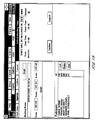
- the organizer's system reports back as shown in Figure 15 so that a preferred meeting time can be selected (only one time is shown available in the example display). If the organizer does not select an option within a specified time period, the reserved times are released on the calendars of the participants to prevent "calendar clutter".
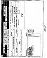
- the organizer's system On selection of the preferred meeting time, the organizer's system then messages each participant, releases the unused times in their calendars and uses their flashing icons to alert them to a possible meeting and to invite them to confirm or refuse attendance: the display is shown in Figure 16. When all participants have responded, the organizer is alerted alerts and invited to finally register or abandon the meeting as shown in Figure 17.
- This display also invites the organizer to the organizer to contact their local conference call service and enter the conference call dial in numbers and password.
- the organizer can also specify which participants are to act as chair and secretary for the meeting, by clicking the Roles button. This button can also be used to specify translators for different languages. These are linked into the conference when participants require translations of shared text.
- This command is used by participants to review the plan for a meeting, the roles of the participants, its agenda and any attachments. It is also used to review the records of past meetings: agendas, minutes and whiteboards.
- the command can be used before a meeting by its chair to change any aspect of the meeting and to send these changes to all participants.
- Clicking Papers and a specific Group button displays a list of all meetings for that group: selecting a specific meeting displays its meeting plan as shown in Figure 18. If the meeting has not yet taken place, an agenda and its attachments can be entered or modified by the chair of the meeting, as shown in Figures 19 and 20.
- the chair is warned of an impending meeting two minutes and the other participants one minute before the scheduled start time.
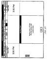
- Their initial displays at the start of the meeting will shows the appropriate number of seats for the meeting surrounding a 'whiteboard" on which the conference call number to dial into is displayed. See Figure 21 for a three person meeting.
- the participant will then dial the conference call number either automatically or manually and enter any password.
- One of the "seats' contains the icon for the local participant. Initially this is shown grayed, signifying that their machine is connected but that they are not yet necessarily present. When the participant clicks on their icon it converts to black signifying that they are now present in the meeting.
- the participant can, using the Help button, specify the amount of information provided about each attendee: the minimum is their first name and the maximum their full name, location and local time. All examples given here show the maximum information.
- the first to dial the conference call number will usually be the chairman.
- the chairman's system will start the Master CRP broadcast as described above. As each new participant successfully connect their modem starts listening for this broadcast, and responds as appropriate. This process continues until all participants report as connected and present.
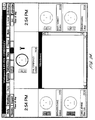
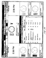
- Figure 22 shows the display for an eight person meeting at this point. As each participant detects the presence of another participant their screen will show that participant's icon grayed on the meeting display. At any time during this set-up process, a connected conference participant can report as present by clicking on their own icon. Participants receiving a "present" broadcast from another member convert the icon for that member from gray to solid. Throughout this period there is no control on the telephones and any one can talk. Once either all the conference participants are present or the chairman decides to start the meeting any way, the chairman calls the meeting to order by selecting Order. This causes
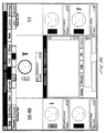
- Figure 24 illustrates the situation where there are 5 conference participants when a meeting has been called to order.
- the two rows of buttons at the top of the display indicate the functions available during a meeting: the labeled buttons are described below.
- the two corner positions around the whiteboard are used to display either time of day, duration of the meeting, time left for the current agenda item or time left for the meeting.
- In the center of the second line from the top there are options available for a conference participant to indicate their level of comprehension and the level of agreement responses to the current speaker.
- the level of comprehension is indicated as Good by a check or Poor by a question mark.
- the level of agreement is indicated by either a smiling face or a sour face.
- Another conference participant can at any time select to indicate the level of comprehension and their emotional response.
- An option is also provided to display an aggregate response, for use where anonymity is preferred.
- the current speaker is signified by a solid ring around their icon, scanned image or video picture.
- the participant who is speaking also has control of the whiteboard and is able to input text on to the whiteboard or import text files or applications on to the whiteboard whereupon all conference participants are able to view this.
- the display indicates who is speaking and for every participant their name, location, local time, whether they are currently present, and their level of understanding and emotional response to the current speaker.
- the chairman who is indicated by the symbolic gavel will not indicate either any emotion or degree of understanding, but will remain neutral.
- the meeting can adopt a range speaking protocols and can switch between them during the course of a meeting.
- the options are selected using the Style command:
- the whiteboard displayed at the center of the display operates under the following rules:
- a translator may be provided (see Set above).
- a translator has a similar system which operates in a different way and must be connected into the telephone conference. Their system receives the text to be translated and this is displayed on the screen. The translator enters the translated text into their system.
- When a conference participant requests a translation by clicking on the translator's icon, they receive the translated whiteboard text from the translator.
- the translator's display is different from that of the conference participants in that the display shows the whiteboard text and simultaneously the translation as it is input by the translator.
- the left hand side displays the untranslated whiteboard and the right hand side the target language.
- the translator's machine will of course include an appropriate keyboard for the language.
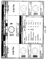
- Figure 25 shows a typical display during a meeting. Mr. Corbishley is the current speaker. Mr. Evans and Ms Harai are queued to speak next. This is indicated by the numbers 1 and 2 which show their position in the queue. Mr. Evans and Ms. Byrne are signifying agreement, and Ms. Harai is signifying disagreement. Ms. Byrne and Ms. Harai are signifying comprehension and Ms. Kenney is signifying lack of comprehension.
- Any participant can select Agenda to display the meeting agenda for review on their whiteboard.
- the chair additionally has the ability to revise the agenda: deleting items, changing their positions or timings, or adding items.
- the chair also uses this command to record the completion of each agenda item.
- Figure 26 gives an example of an agenda display, as seen by the chair and figure 28 shows the display after an agenda item has been marked as completed.
- This option is only available to the chair.
- the Vote option the display shown in Figure 29 appears. The chair then enters the text indicating the motion and selects a time for the vote. Once this is done, they select Ballot to start the balloting.
- This option allows a conference participant to pass a private text message to one or more conference participant.
- a window overlays the whiteboard and allows entry of the identity of the sender and the receiver, a text message and space allowed for a text reply. After the text is entered the message can be sent by appropriate selection of options.
- the sender's icon shows a flashing name box.
- the recipient(s) can display the note on their whiteboard by clicking on the sender's icon.
- the recipient(s) can either then reply or indicate that there is no reply.
- the reply or indication that there is no reply is then re-transmitted to the sender.
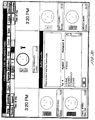
- Figure 31 is an example of a display of Mr. Evans responding to a note from Ms. Kenney.
- This command provides the entire width of the display to the whiteboard, compressing the participant information into a single line.
- Figure 32 is an example.
- This command is used to set up another meeting during a meeting and operates in a similar manner to the Out of Meeting Set command.
- a single conference participant uses a single telephone line and computer, it is possible for a number of users to share the same telephone line and the same computer. If this is the case, the system indicates that there are for example 4 conference participants at the single location. The 4 conference participants appoint a sub-chairman to operate the keyboard and provide a democratic response. All other features remain unchanged.
- the embodiments of the present invention described herein above refer to the use of a computer connected to a data over voice modem provided within a telephone handset, it will be appreciated that the processor could be provided within the telephone handset and programmable via a keypad provided thereon. A small LCD display or a series of LED's would suffice to provide indications of the responses of conference participants to conference presentations or events.
- the microphone of a conference participant can be enabled or disabled.
- an arrangement is provided to detect speech which is detected by the microphone and signal this to the processor by for example the RS232 line. This facility provides a signal every time a conference participant speaks which can be used for instance to identify the speaker.
- the present invention is also applicable to conferences wherein the conference participants are at a single location.
- the provision of a common display or discrete displays together with discrete input means would allow conference participants to view the responses of other conference participants to a presentation by one conference participant.
- This arrangement also provides the chairman with some degree of control, especially where microphones are used during the conference since the chairman would be able to enable and disable microphones as required and speakers requesting to speak would be indicated on the display.
- many different types of conference parameters can be displayed on the display means, thereby greatly enhancing the communication possible during a conference.
Landscapes
- Engineering & Computer Science (AREA)
- Multimedia (AREA)
- Signal Processing (AREA)
- Computer Networks & Wireless Communication (AREA)
- Data Exchanges In Wide-Area Networks (AREA)
- Two-Way Televisions, Distribution Of Moving Picture Or The Like (AREA)
- Telephonic Communication Services (AREA)
Applications Claiming Priority (2)
| Application Number | Priority Date | Filing Date | Title |
|---|---|---|---|
| GB9215662 | 1992-07-23 | ||
| GB929215662A GB9215662D0 (en) | 1992-07-23 | 1992-07-23 | Conference assisting apparatus |
Publications (2)
| Publication Number | Publication Date |
|---|---|
| EP0580397A2 true EP0580397A2 (de) | 1994-01-26 |
| EP0580397A3 EP0580397A3 (de) | 1995-01-25 |
Family
ID=10719176
Family Applications (1)
| Application Number | Title | Priority Date | Filing Date |
|---|---|---|---|
| EP93305681A Withdrawn EP0580397A3 (de) | 1992-07-23 | 1993-07-20 | Konferenzgerät. |
Country Status (2)
| Country | Link |
|---|---|
| EP (1) | EP0580397A3 (de) |
| GB (1) | GB9215662D0 (de) |
Cited By (26)
| Publication number | Priority date | Publication date | Assignee | Title |
|---|---|---|---|---|
| EP0717345A1 (de) * | 1994-12-16 | 1996-06-19 | AT&T Corp. | Graphische Benutzerschnittstelle für Multimedia-Anrufaufbau und -Bearbeitung |
| US5559875A (en) * | 1995-07-31 | 1996-09-24 | Latitude Communications | Method and apparatus for recording and retrieval of audio conferences |
| GB2303516A (en) * | 1995-07-20 | 1997-02-19 | Plessey Telecomm | Teleconferencing |
| GB2303517A (en) * | 1995-07-20 | 1997-02-19 | Plessey Telecomm | Teleconferencing |
| WO1998059256A3 (en) * | 1997-06-25 | 1999-05-14 | Navox Corp | Vehicle tracking and security system incorporating simultaneous voice and data communication |
| EP0724352A3 (de) * | 1995-01-25 | 1999-11-17 | Alcatel Austria Aktiengesellschaft | Konferenzsystem |
| RU2154911C2 (ru) * | 1995-12-08 | 2000-08-20 | Самсунг Электроникс Ко., Лтд. | Устройство коммутации и конференц-связи в системе обмена информацией |
| US6215486B1 (en) * | 1998-07-20 | 2001-04-10 | Hewlett-Packard Company | Event handling in a single logical screen display using multiple remote computer systems |
| EP1094657A1 (de) * | 1999-10-18 | 2001-04-25 | BRITISH TELECOMMUNICATIONS public limited company | Mobilkonferenzsystem und Verfahren |
| US6538684B1 (en) * | 1994-11-29 | 2003-03-25 | Canon Kabushiki Kaisha | Television conference system indicating time data |
| GB2429614A (en) * | 2005-08-22 | 2007-02-28 | Infineon Technologies Ag | Voting in a conference system using control protocol messages |
| WO2007051493A1 (en) * | 2005-11-07 | 2007-05-10 | Telecom Italia S.P.A. | Method for managing a conference call in a telephone network |
| EP1580999A3 (de) * | 2004-02-25 | 2009-02-25 | Pioneer Corporation | Netzwerkkonferenzsystem, Managementserver, Konferenzendgerät und Informationsoriginisierungs Berechtigungsverwaltungsmethode |
| US7508810B2 (en) | 2005-01-31 | 2009-03-24 | Airbiquity Inc. | Voice channel control of wireless packet data communications |
| US7747281B2 (en) | 1997-05-19 | 2010-06-29 | Airbiquity Inc. | Method for in-band signaling of data over digital wireless telecommunications networks |
| US7848763B2 (en) | 2001-11-01 | 2010-12-07 | Airbiquity Inc. | Method for pulling geographic location data from a remote wireless telecommunications mobile unit |
| US7924934B2 (en) | 2006-04-07 | 2011-04-12 | Airbiquity, Inc. | Time diversity voice channel data communications |
| US7979095B2 (en) | 2007-10-20 | 2011-07-12 | Airbiquity, Inc. | Wireless in-band signaling with in-vehicle systems |
| US7983310B2 (en) | 2008-09-15 | 2011-07-19 | Airbiquity Inc. | Methods for in-band signaling through enhanced variable-rate codecs |
| US8068792B2 (en) | 1998-05-19 | 2011-11-29 | Airbiquity Inc. | In-band signaling for data communications over digital wireless telecommunications networks |
| US8073440B2 (en) | 2009-04-27 | 2011-12-06 | Airbiquity, Inc. | Automatic gain control in a personal navigation device |
| US20120004953A1 (en) * | 2010-06-30 | 2012-01-05 | Paul Comito | Voting system |
| US8249865B2 (en) | 2009-11-23 | 2012-08-21 | Airbiquity Inc. | Adaptive data transmission for a digital in-band modem operating over a voice channel |
| US8418039B2 (en) | 2009-08-03 | 2013-04-09 | Airbiquity Inc. | Efficient error correction scheme for data transmission in a wireless in-band signaling system |
| US8594138B2 (en) | 2008-09-15 | 2013-11-26 | Airbiquity Inc. | Methods for in-band signaling through enhanced variable-rate codecs |
| US8848825B2 (en) | 2011-09-22 | 2014-09-30 | Airbiquity Inc. | Echo cancellation in wireless inband signaling modem |
Family Cites Families (3)
| Publication number | Priority date | Publication date | Assignee | Title |
|---|---|---|---|---|
| US4785472A (en) * | 1987-05-11 | 1988-11-15 | The Trustees Of The Stevens Institute Of Technology | Remote teaching system |
| US4953159A (en) * | 1989-01-03 | 1990-08-28 | American Telephone And Telegraph Company | Audiographics conferencing arrangement |
| US5195086A (en) * | 1990-04-12 | 1993-03-16 | At&T Bell Laboratories | Multiple call control method in a multimedia conferencing system |
-
1992
- 1992-07-23 GB GB929215662A patent/GB9215662D0/en active Pending
-
1993
- 1993-07-20 EP EP93305681A patent/EP0580397A3/de not_active Withdrawn
Cited By (37)
| Publication number | Priority date | Publication date | Assignee | Title |
|---|---|---|---|---|
| US6538684B1 (en) * | 1994-11-29 | 2003-03-25 | Canon Kabushiki Kaisha | Television conference system indicating time data |
| EP0717345A1 (de) * | 1994-12-16 | 1996-06-19 | AT&T Corp. | Graphische Benutzerschnittstelle für Multimedia-Anrufaufbau und -Bearbeitung |
| EP0724352A3 (de) * | 1995-01-25 | 1999-11-17 | Alcatel Austria Aktiengesellschaft | Konferenzsystem |
| EP0755145A3 (de) * | 1995-07-20 | 1999-05-19 | Siemens Plc | Telekonferenz |
| GB2303516A (en) * | 1995-07-20 | 1997-02-19 | Plessey Telecomm | Teleconferencing |
| GB2303517A (en) * | 1995-07-20 | 1997-02-19 | Plessey Telecomm | Teleconferencing |
| US5668863A (en) * | 1995-07-31 | 1997-09-16 | Latitude Communications | Method and apparatus for recording and retrieval of audio conferences |
| US5559875A (en) * | 1995-07-31 | 1996-09-24 | Latitude Communications | Method and apparatus for recording and retrieval of audio conferences |
| RU2154911C2 (ru) * | 1995-12-08 | 2000-08-20 | Самсунг Электроникс Ко., Лтд. | Устройство коммутации и конференц-связи в системе обмена информацией |
| US7747281B2 (en) | 1997-05-19 | 2010-06-29 | Airbiquity Inc. | Method for in-band signaling of data over digital wireless telecommunications networks |
| WO1998059256A3 (en) * | 1997-06-25 | 1999-05-14 | Navox Corp | Vehicle tracking and security system incorporating simultaneous voice and data communication |
| US8068792B2 (en) | 1998-05-19 | 2011-11-29 | Airbiquity Inc. | In-band signaling for data communications over digital wireless telecommunications networks |
| US6215486B1 (en) * | 1998-07-20 | 2001-04-10 | Hewlett-Packard Company | Event handling in a single logical screen display using multiple remote computer systems |
| EP1094657A1 (de) * | 1999-10-18 | 2001-04-25 | BRITISH TELECOMMUNICATIONS public limited company | Mobilkonferenzsystem und Verfahren |
| WO2001030059A1 (en) * | 1999-10-18 | 2001-04-26 | British Telecommunications Public Limited Company | Mobile conferencing system and method |
| US7848763B2 (en) | 2001-11-01 | 2010-12-07 | Airbiquity Inc. | Method for pulling geographic location data from a remote wireless telecommunications mobile unit |
| EP1580999A3 (de) * | 2004-02-25 | 2009-02-25 | Pioneer Corporation | Netzwerkkonferenzsystem, Managementserver, Konferenzendgerät und Informationsoriginisierungs Berechtigungsverwaltungsmethode |
| US7733853B2 (en) | 2005-01-31 | 2010-06-08 | Airbiquity, Inc. | Voice channel control of wireless packet data communications |
| US7508810B2 (en) | 2005-01-31 | 2009-03-24 | Airbiquity Inc. | Voice channel control of wireless packet data communications |
| US8036201B2 (en) | 2005-01-31 | 2011-10-11 | Airbiquity, Inc. | Voice channel control of wireless packet data communications |
| GB2429614A (en) * | 2005-08-22 | 2007-02-28 | Infineon Technologies Ag | Voting in a conference system using control protocol messages |
| GB2429614B (en) * | 2005-08-22 | 2007-12-05 | Infineon Technologies Ag | Voting systems |
| WO2007051493A1 (en) * | 2005-11-07 | 2007-05-10 | Telecom Italia S.P.A. | Method for managing a conference call in a telephone network |
| US8270957B2 (en) | 2005-11-07 | 2012-09-18 | Telecom Italia S.P.A. | Method for managing a conference call in a telephone network |
| US7924934B2 (en) | 2006-04-07 | 2011-04-12 | Airbiquity, Inc. | Time diversity voice channel data communications |
| US7979095B2 (en) | 2007-10-20 | 2011-07-12 | Airbiquity, Inc. | Wireless in-band signaling with in-vehicle systems |
| US8369393B2 (en) | 2007-10-20 | 2013-02-05 | Airbiquity Inc. | Wireless in-band signaling with in-vehicle systems |
| US7983310B2 (en) | 2008-09-15 | 2011-07-19 | Airbiquity Inc. | Methods for in-band signaling through enhanced variable-rate codecs |
| US8594138B2 (en) | 2008-09-15 | 2013-11-26 | Airbiquity Inc. | Methods for in-band signaling through enhanced variable-rate codecs |
| US8073440B2 (en) | 2009-04-27 | 2011-12-06 | Airbiquity, Inc. | Automatic gain control in a personal navigation device |
| US8195093B2 (en) | 2009-04-27 | 2012-06-05 | Darrin Garrett | Using a bluetooth capable mobile phone to access a remote network |
| US8346227B2 (en) | 2009-04-27 | 2013-01-01 | Airbiquity Inc. | Automatic gain control in a navigation device |
| US8452247B2 (en) | 2009-04-27 | 2013-05-28 | Airbiquity Inc. | Automatic gain control |
| US8418039B2 (en) | 2009-08-03 | 2013-04-09 | Airbiquity Inc. | Efficient error correction scheme for data transmission in a wireless in-band signaling system |
| US8249865B2 (en) | 2009-11-23 | 2012-08-21 | Airbiquity Inc. | Adaptive data transmission for a digital in-band modem operating over a voice channel |
| US20120004953A1 (en) * | 2010-06-30 | 2012-01-05 | Paul Comito | Voting system |
| US8848825B2 (en) | 2011-09-22 | 2014-09-30 | Airbiquity Inc. | Echo cancellation in wireless inband signaling modem |
Also Published As
| Publication number | Publication date |
|---|---|
| EP0580397A3 (de) | 1995-01-25 |
| GB9215662D0 (en) | 1992-09-09 |
Similar Documents
| Publication | Publication Date | Title |
|---|---|---|
| EP0580397A2 (de) | Konferenzgerät | |
| Vin et al. | Multimedia conferencing in the Etherphone environment | |
| US6100882A (en) | Textual recording of contributions to audio conference using speech recognition | |
| Mark et al. | Meeting at the desktop: An empirical study of virtually collocated teams | |
| EP1377005B1 (de) | Zusammenarbeit mittels Instant Messaging in multimedialen Telefonie-über-LAN Konferenzen | |
| US6914519B2 (en) | System and method for muting alarms during a conference | |
| US7734692B1 (en) | Network collaboration system with private voice chat | |
| US6839417B2 (en) | Method and apparatus for improved conference call management | |
| EP0898424B1 (de) | Multimedia Telekonferenzsystem | |
| US20070208806A1 (en) | Network collaboration system with conference waiting room | |
| US20050018828A1 (en) | System and method for indicating a speaker during a conference | |
| US20060067499A1 (en) | Method and apparatus for querying a list of participants in a conference | |
| US20060147009A1 (en) | Integrated voice and video conferencing management | |
| US20040250201A1 (en) | System and method for indicating an annotation for a document | |
| CN102694665A (zh) | 通知参与者会议开始 | |
| WO1998004989A1 (en) | Apparatus and method for multi-station conferencing | |
| WO2000060809A8 (en) | Apparatus and method for establishing an audio conference in a networked environment | |
| Swinehart et al. | Adding voice to an office computer network | |
| EP1661024A2 (de) | Verfahren und system zur bereitstellung von konferenzdiensten | |
| WO2008104500A2 (en) | Method and system for managing simultaneous electronic communications | |
| WO2006127160A2 (en) | Media conference enhancements | |
| Kellogg et al. | Leveraging digital backchannels to enhance user experience in electronically mediated communication | |
| Maeno et al. | Distributed desktop conferencing system (MERMAID) based on group communication architecture | |
| Schooler et al. | Multimedia conferencing: Has it come of age? | |
| CA2296187C (en) | Synchronization in video conferencing |
Legal Events
| Date | Code | Title | Description |
|---|---|---|---|
| PUAI | Public reference made under article 153(3) epc to a published international application that has entered the european phase |
Free format text: ORIGINAL CODE: 0009012 |
|
| AK | Designated contracting states |
Kind code of ref document: A2 Designated state(s): DE ES FR GB IE IT NL |
|
| PUAL | Search report despatched |
Free format text: ORIGINAL CODE: 0009013 |
|
| AK | Designated contracting states |
Kind code of ref document: A3 Designated state(s): DE ES FR GB IE IT NL |
|
| STAA | Information on the status of an ep patent application or granted ep patent |
Free format text: STATUS: THE APPLICATION IS DEEMED TO BE WITHDRAWN |
|
| 18D | Application deemed to be withdrawn |
Effective date: 19950726 |