EP0580443A2 - Elastische Kupplung - Google Patents
Elastische Kupplung Download PDFInfo
- Publication number
- EP0580443A2 EP0580443A2 EP93305814A EP93305814A EP0580443A2 EP 0580443 A2 EP0580443 A2 EP 0580443A2 EP 93305814 A EP93305814 A EP 93305814A EP 93305814 A EP93305814 A EP 93305814A EP 0580443 A2 EP0580443 A2 EP 0580443A2
- Authority
- EP
- European Patent Office
- Prior art keywords
- flexible coupling
- coupling
- elements
- rubber
- fixing means
- Prior art date
- Legal status (The legal status is an assumption and is not a legal conclusion. Google has not performed a legal analysis and makes no representation as to the accuracy of the status listed.)
- Granted
Links
Images


Classifications
-
- F—MECHANICAL ENGINEERING; LIGHTING; HEATING; WEAPONS; BLASTING
- F16—ENGINEERING ELEMENTS AND UNITS; GENERAL MEASURES FOR PRODUCING AND MAINTAINING EFFECTIVE FUNCTIONING OF MACHINES OR INSTALLATIONS; THERMAL INSULATION IN GENERAL
- F16D—COUPLINGS FOR TRANSMITTING ROTATION; CLUTCHES; BRAKES
- F16D3/00—Yielding couplings, i.e. with means permitting movement between the connected parts during the drive
- F16D3/50—Yielding couplings, i.e. with means permitting movement between the connected parts during the drive with the coupling parts connected by one or more intermediate members
- F16D3/76—Yielding couplings, i.e. with means permitting movement between the connected parts during the drive with the coupling parts connected by one or more intermediate members shaped as an elastic ring centered on the axis, surrounding a portion of one coupling part and surrounded by a sleeve of the other coupling part
-
- F—MECHANICAL ENGINEERING; LIGHTING; HEATING; WEAPONS; BLASTING
- F16—ENGINEERING ELEMENTS AND UNITS; GENERAL MEASURES FOR PRODUCING AND MAINTAINING EFFECTIVE FUNCTIONING OF MACHINES OR INSTALLATIONS; THERMAL INSULATION IN GENERAL
- F16D—COUPLINGS FOR TRANSMITTING ROTATION; CLUTCHES; BRAKES
- F16D3/00—Yielding couplings, i.e. with means permitting movement between the connected parts during the drive
- F16D3/50—Yielding couplings, i.e. with means permitting movement between the connected parts during the drive with the coupling parts connected by one or more intermediate members
- F16D3/70—Yielding couplings, i.e. with means permitting movement between the connected parts during the drive with the coupling parts connected by one or more intermediate members comprising elastic elements arranged in holes in one coupling part and surrounding pins on the other coupling part
Definitions
- Known flexible couplings of this kind are often used to connect an engine flywheel to a driven component of the engine for example the gearbox or alternator.
- These couplings are substantially disc shaped having an inner metallic member connected to an outer metallic ring via a rubber body which is vulcanised to the inner member.
- the inner member of the coupling is connected to the driven component and the ring is bolted to the engine flywheel.
- the rubber body provides the torsional flexibility of the coupling.
- the rubber body has peripheral teeth which engage with corresponding teeth on the outer ring.
- the teeth on the outer ring and the rubber body allow the coupling to be assembled blind.
- This type of coupling has several disadvantages. Under load there is a tendency for adjacent engaging teeth to disengage, slip over each other and to re-engage with the next tooth. This causes undesirable wear on the teeth and ultimately ruins the coupling.
- the rubber teeth on the rubber body tend to swell during rotation and grip tightly the outer ring. This induces friction between them and effectively prevents axial movement between the rubber and the outer ring.
- Axial movement is desirable in flexible couplings to help provide compensation for any misalignment of the coupled components.
- a flexible coupling for interconnecting machine components comprising a resilient annular body fixed to rigid inner and outer annular members for connection to respective machine components, characterised in that said body has angularly spaced holes adjacent its outer periphery and said holes are lined by elements of said outer member.
- the elements of said outer member are tubular, interconnected by arcuate connecting pieces and are smaller in width than the elements such that the connecting pieces are embedded in the annular body.
- the annular body extends radially beyond the periphery of the outer member and over the arcuate connecting pieces giving extra torsional flexibility in the coupling.
- the connecting pieces are preferably T-shaped in section with the stem of the T directed radially outwardly.
- the elements have a resilient lining which may have a tapered bore such that fixing means for connecting the coupling to a machine component can be received in the bore and compresses the lining.
- the bore may be tapered from both ends such that the minimum diameter of the bore is at the centre.
- the provision of the compressible resilient lining serves to reduce backlash in the coupling to a very low value.
- a flexible coupling assembly comprising a flexible coupling as defined above, and fixing means for connecting the outer annular member to its machine component.
- the fixing means comprises a plurality of drive pins each of which is engageable in a respective one of said elements of said outer member.
- the drive pins have free ends engageable in said elements so as to permit blind fitting of the coupling with respect to the fixing means.
- the fixing means may also comprise a locating member adapted to be fixed to said machine component, the locating member having a plurality of recesses which engage with respective spigots on the adjacent ends of the drive pins.
- a failsafe mechanism which comprises at least one inward projection of said locating member and at least one outward projection from said inner member angularly spaced from said inward projection so as to maintain drive transmission in the event of failure of the coupling.
- the flexible coupling generally indicated by arrow 1 is connected between a hub 2 and a flywheel 3 of an internal combustion engine.
- the hub 2 is machined to fit on to a shaft of a driven component of the engine, for example, the gearbox or the alternator.
- the coupling has a main body 4 of rubber and is connected at its outer end to the flywheel 3.
- An inner member 5 of cylindrical shape and having a radially inwardly directed flange 6 is connected to the hub 2 by a plurality of equiangularly spaced screws 7 which pass through the flange 6.
- the inner member 5 is vulcanised on its outer surface to the main body 4 of rubber.
- the main body 4 of rubber is of disc-like configuration having faces with radially outward tapers so that the axial thickness of the body 4 diminishes radially outwards.
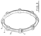
- the body 4 has embedded in it, adjacent its outer edge, a metal reinforcement skeleton 8 which is shown in detail in figure 3.
- the skeleton 8 comprises a plurality of equiangularly spaced tubes 9 which are linked together by arcuate bridges 9a of inverted T-shaped cross section (see figure 4) to form a complete ring.
- each tube 9 is lined with a rubber tube 10 formed from rubber which is harder than the rubber of the main body 4.
- the rubber tube 10 is internally tapered from both ends to a minimum diameter at the centre.
- a sleeve 11 which is slightly longer than the rubber tube 10.
- One end of the sleeve 11 has rounded edges 12 and the other end has a spigot formation 13.
- the minimum inside diameter of the rubber tube 10 is slightly less than the outside diameter of the sleeve 11.
- a location ring 14 fits into a recess 15 provided in the flywheel 3.
- the location ring 14 is drilled and counterbored to match the hole pattern in the flywheel 3.
- the spigot 13 on each sleeve 11 locates in the corresponding counterbore in the location ring 14.
- the coupling 1 is fixed to the flywheel 3 by means of screws 16 which pass through bores in the sleeves 11 and the location ring 14 to engage in a threaded bore in the flywheel 3.
- the sleeves 11 may, in an alternative embodiment, be counterbored to receive the head of each screw 16.
- the coupling 1 is assembled in the following manner.
- the location ring 14 and sleeves 11 are attached to the flywheel 3 by means of the screws 16 and the hub 2 is connected to the driven machine shaft by means of, for example, a key.
- the coupling 1 comprising the rubber body 4, the inner member 5, the skeleton 8 and the rubber tubes 10 is then connected to the hub 2 by means of screws 7.
- the rubber tubes 10 are lubricated with, for example, silicon fluid.
- the coupling 1 and the flywheel 3 can then be assembled blind by bringing them together and aligning the sleeves 11 to their respective holes in the coupling 1 by feel.
- the engine and driven machine are then pushed together such that the sleeves 11 enter the rubber tubes 10.
- the rounded edges 12 of the sleeves 11 and the tapered bores of the rubber tubes 10 facilitate entry of the sleeves 11 into the tubes 10.
- the rubber body 4 is tapered as described to provide for uniform torsional strength throughout the coupling.
- the arrangement of the sleeves 11 in the tubes 10 provides for a very low axial stiffness in the coupling. As the friction force between the sleeves 11 and the rubber tubes 10 is not great the coupling is allowed to slide axially on the sleeves 11 whilst in use. This axial movement is desirable in couplings to provide compensation for any misalignment of the coupled components.
- the relatively high radial stiffness of the connection ensures that the torque load or centrifugal stresses do not tend to cause swelling of the rubber tubes 10 and thus they have little or no effect on the axial stiffness.
- the skeleton 8 is bonded to the rubber body 4 over a large surface area such that the stress of the rubber to metal bond has a relatively low value.
- the skeleton 8 acts to reinforce the harder rubber of the tubes 10 and provides a strong connection resistant to localised deformation of the rubber.
- the skeleton 8 and the rubber tubes 10 preloaded by the sleeves 11 act to eliminate virtually all backlash.
- the provision of a rubber body 4 which entirely encompasses the skeleton 8 and therefore the connection holes gives extra flexibility in the coupling 1 compared with known couplings of this kind. This allows the rubber to have a lower stiffness without overstressing the rubber.
- the bridges 9a of the skeleton 8 provide restraint from centrifugal forces acting on the connection tubes 9 and the associated fixings as the coupling rotates, and help to reduce the stress concentration in its rubber body near each tube 9.
- the coupling provides extra torsional flexibility whilst minimising backlash and allowing blind assembly.
- the coupling of the present invention can also be used in applications where blind fitting is not required.
- the coupling can be bolted to the flywheel once the tubes 9 of the reinforcement skeleton 8 have been aligned to the holes in the flywheel.
- the backlash in these cases will be zero.
- couplings may be provided which do not have the rubber tubes 10 lining the tubes 9 of the reinforcement skeleton 8.
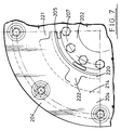
- Figures 6 and 7 show a further alternative embodiment in which parts common to the first embodiment are given the same reference numeral but incremented by a value of 200. For convenience only part of the coupling is shown, the rest of the coupling being the mirror image of the part shown about the centre lines.
- the location ring 214 extends radially inwardly from the flywheel connection.
- An inner limit ring 220 is connected in the same plane as the location ring 214 to the hub 202 and inner member 205 by means of screws 207.
- the location ring 214 has radially inwardly extending projections 221 which project into the spaces between corresponding outwardly extending projections 222 on the inner limit ring 220. This arrangement acts as a failsafe mechanism.
- the degree of relative rotational motion between the hub 202 and the flywheel 203 is limited by the abutment of the projections 221,222 on the limit ring 220 and location ring 214.
- the projections 221,222 enable the drive to be transmitted by the coupling until the requisite repair action can be taken.
Landscapes
- Engineering & Computer Science (AREA)
- General Engineering & Computer Science (AREA)
- Mechanical Engineering (AREA)
- Shafts, Cranks, Connecting Bars, And Related Bearings (AREA)
Applications Claiming Priority (3)
| Application Number | Priority Date | Filing Date | Title |
|---|---|---|---|
| GB929215518A GB9215518D0 (en) | 1992-07-22 | 1992-07-22 | A flexible coupling |
| GB9215518 | 1992-07-22 | ||
| US08/110,238 US5514038A (en) | 1992-07-22 | 1993-08-23 | Flexible coupling facilitating blind assembly |
Publications (3)
| Publication Number | Publication Date |
|---|---|
| EP0580443A2 true EP0580443A2 (de) | 1994-01-26 |
| EP0580443A3 EP0580443A3 (en) | 1994-09-07 |
| EP0580443B1 EP0580443B1 (de) | 1996-12-18 |
Family
ID=26301296
Family Applications (1)
| Application Number | Title | Priority Date | Filing Date |
|---|---|---|---|
| EP93305814A Expired - Lifetime EP0580443B1 (de) | 1992-07-22 | 1993-07-21 | Elastische Kupplung |
Country Status (2)
| Country | Link |
|---|---|
| US (1) | US5514038A (de) |
| EP (1) | EP0580443B1 (de) |
Cited By (5)
| Publication number | Priority date | Publication date | Assignee | Title |
|---|---|---|---|---|
| EP1002966A1 (de) * | 1998-11-20 | 2000-05-24 | Stromag AG | Elastische Wellenkupplung |
| US6117016A (en) * | 1997-01-25 | 2000-09-12 | Agco Gmbh & Co. | Transmission coupling assembly |
| US6402308B1 (en) | 1999-06-24 | 2002-06-11 | Canon Kabushiki Kaisha | Liquid supply system and liquid supply vessel used for the same |
| RU2274780C1 (ru) * | 2004-09-07 | 2006-04-20 | Иосиф Александрович Трибельский | Упругая муфта |
| RU2282070C2 (ru) * | 2004-09-07 | 2006-08-20 | Иосиф Александрович Трибельский | Упругая муфта |
Families Citing this family (9)
| Publication number | Priority date | Publication date | Assignee | Title |
|---|---|---|---|---|
| US6074122A (en) * | 1997-12-15 | 2000-06-13 | Caterpillar Inc. | Cone drive power train connection |
| US20030157987A1 (en) * | 2000-10-26 | 2003-08-21 | Kop Flex, Inc. | Shaft couplings with bonded flexible elements |
| US7704009B2 (en) * | 2005-03-25 | 2010-04-27 | Boote Carey J | Axial spacer for a rotational assembly |
| DE102005055605A1 (de) * | 2005-11-22 | 2007-05-31 | Centa-Antriebe Kirschey Gmbh | Elastische Wellenkupplung |
| US20070295153A1 (en) * | 2006-06-13 | 2007-12-27 | Burdeshaw Galen E | Combination compression/diaphragm coupling system |
| CN100478574C (zh) * | 2006-10-20 | 2009-04-15 | 重庆大学 | 高弹性橡胶合金联轴器 |
| DE102008005257C5 (de) * | 2008-01-18 | 2016-12-22 | Centa-Antriebe Kirschey Gmbh | Drehelastische Wellenkupplung |
| US9065307B2 (en) | 2012-08-03 | 2015-06-23 | Kohler Co. | Apparatus for facilitating attachment of fan and flywheel in an internal combustion engine |
| CN112128259B (zh) * | 2020-09-21 | 2021-08-13 | 株洲时代新材料科技股份有限公司 | 一种橡胶衬套联轴器 |
Family Cites Families (11)
| Publication number | Priority date | Publication date | Assignee | Title |
|---|---|---|---|---|
| BE475957A (de) * | ||||
| US1396979A (en) * | 1921-02-21 | 1921-11-15 | Flexible Couplings Company | Flexible shaft-coupling |
| US2460628A (en) * | 1943-02-15 | 1949-02-01 | Thomas L Fawick | Flexible coupling |
| GB1159750A (en) * | 1966-11-26 | 1969-07-30 | Daimler Benz Ag | Improvements relating to Shaft Couplings. |
| DE2942874A1 (de) * | 1979-10-24 | 1981-04-30 | Gerhard Dipl.-Ing. 5600 Wuppertal Kirschey | Elastische wellenkupplung |
| EP0106579A3 (de) * | 1982-09-23 | 1985-05-08 | Supra Group Plc | Elastische Kupplung |
| JPH027278Y2 (de) * | 1984-09-10 | 1990-02-21 | ||
| GB2235034A (en) * | 1989-07-13 | 1991-02-20 | Holset Engineering Co | Flexible coupling |
| DE3942797A1 (de) * | 1989-12-23 | 1991-07-04 | Bayerische Motoren Werke Ag | Antriebsverbindung zwischen zwei wellen in einem kraftfahrzeug |
| DE9206358U1 (de) * | 1992-05-12 | 1992-10-01 | Centa-Antriebe Kirschey GmbH, 5657 Haan | Drehelastische Kupplung |
| US5195625A (en) * | 1992-05-29 | 1993-03-23 | General Motors Corporation | Torque cushion for electromagnetic clutch |
-
1993
- 1993-07-21 EP EP93305814A patent/EP0580443B1/de not_active Expired - Lifetime
- 1993-08-23 US US08/110,238 patent/US5514038A/en not_active Expired - Lifetime
Cited By (5)
| Publication number | Priority date | Publication date | Assignee | Title |
|---|---|---|---|---|
| US6117016A (en) * | 1997-01-25 | 2000-09-12 | Agco Gmbh & Co. | Transmission coupling assembly |
| EP1002966A1 (de) * | 1998-11-20 | 2000-05-24 | Stromag AG | Elastische Wellenkupplung |
| US6402308B1 (en) | 1999-06-24 | 2002-06-11 | Canon Kabushiki Kaisha | Liquid supply system and liquid supply vessel used for the same |
| RU2274780C1 (ru) * | 2004-09-07 | 2006-04-20 | Иосиф Александрович Трибельский | Упругая муфта |
| RU2282070C2 (ru) * | 2004-09-07 | 2006-08-20 | Иосиф Александрович Трибельский | Упругая муфта |
Also Published As
| Publication number | Publication date |
|---|---|
| EP0580443B1 (de) | 1996-12-18 |
| EP0580443A3 (en) | 1994-09-07 |
| US5514038A (en) | 1996-05-07 |
Similar Documents
| Publication | Publication Date | Title |
|---|---|---|
| EP0580443B1 (de) | Elastische Kupplung | |
| US7707703B2 (en) | Flexible couplings | |
| US4781486A (en) | Shaft coupling | |
| US5545089A (en) | Shaft coupling | |
| CA2103949C (en) | Engine/transmission rotary connection | |
| US4413393A (en) | Method of manufacturing a valve assembly | |
| GB2153969A (en) | Means for use in connecting a drive coupling to a non-splined end of a pump drive member | |
| JPH0674813B2 (ja) | 全スチ−ル製たわみ継ぎ手 | |
| KR930004567B1 (ko) | 마찰 라이닝 지지판과 허브를 결합시키는 스프링 콜릿을 갖는 마찰요소 | |
| JPH0146738B2 (de) | ||
| US4307584A (en) | Resilient coupling mechanism | |
| EP0824202B1 (de) | Kupplungsmethode und Kupplungsvorrichtung | |
| US20120099926A1 (en) | Hub-shaft assembly | |
| US20060019756A1 (en) | Flexible drive interface | |
| JP2023127554A (ja) | 駆動機構、および、車両 | |
| US4701068A (en) | Spline anti-backlash device | |
| KR880000812B1 (ko) | 축계수 | |
| US6117017A (en) | Insertable toothed coupling | |
| US5382194A (en) | Plug-in axially and angularly yieldable toothed coupling for transmitting torque | |
| CA1085639A (en) | Thrust cancelling shaft coupling | |
| KR20220078631A (ko) | 커플링 | |
| WO1988002074A1 (en) | Bolted coupling | |
| RU2153607C2 (ru) | Гибкая муфта для трансмиссионных систем | |
| US20050197193A1 (en) | Temporary repair device for mechanical drive couplings | |
| US5964662A (en) | Thrust coupler |
Legal Events
| Date | Code | Title | Description |
|---|---|---|---|
| PUAI | Public reference made under article 153(3) epc to a published international application that has entered the european phase |
Free format text: ORIGINAL CODE: 0009012 |
|
| AK | Designated contracting states |
Kind code of ref document: A2 Designated state(s): DE FR GB |
|
| PUAL | Search report despatched |
Free format text: ORIGINAL CODE: 0009013 |
|
| AK | Designated contracting states |
Kind code of ref document: A3 Designated state(s): DE FR GB |
|
| 17P | Request for examination filed |
Effective date: 19941230 |
|
| 17Q | First examination report despatched |
Effective date: 19951103 |
|
| GRAG | Despatch of communication of intention to grant |
Free format text: ORIGINAL CODE: EPIDOS AGRA |
|
| GRAH | Despatch of communication of intention to grant a patent |
Free format text: ORIGINAL CODE: EPIDOS IGRA |
|
| GRAH | Despatch of communication of intention to grant a patent |
Free format text: ORIGINAL CODE: EPIDOS IGRA |
|
| GRAA | (expected) grant |
Free format text: ORIGINAL CODE: 0009210 |
|
| AK | Designated contracting states |
Kind code of ref document: B1 Designated state(s): DE FR GB |
|
| RAP1 | Party data changed (applicant data changed or rights of an application transferred) |
Owner name: RENOLD HOLSET COUPLINGS LIMITED |
|
| REF | Corresponds to: |
Ref document number: 69306684 Country of ref document: DE Date of ref document: 19970130 |
|
| ET | Fr: translation filed | ||
| PLBE | No opposition filed within time limit |
Free format text: ORIGINAL CODE: 0009261 |
|
| STAA | Information on the status of an ep patent application or granted ep patent |
Free format text: STATUS: NO OPPOSITION FILED WITHIN TIME LIMIT |
|
| 26N | No opposition filed | ||
| REG | Reference to a national code |
Ref country code: GB Ref legal event code: 732E |
|
| REG | Reference to a national code |
Ref country code: FR Ref legal event code: TP Ref country code: FR Ref legal event code: CD |
|
| PGFP | Annual fee paid to national office [announced via postgrant information from national office to epo] |
Ref country code: GB Payment date: 19980812 Year of fee payment: 6 |
|
| PGFP | Annual fee paid to national office [announced via postgrant information from national office to epo] |
Ref country code: DE Payment date: 19980817 Year of fee payment: 6 |
|
| PGFP | Annual fee paid to national office [announced via postgrant information from national office to epo] |
Ref country code: FR Payment date: 19980827 Year of fee payment: 6 |
|
| PG25 | Lapsed in a contracting state [announced via postgrant information from national office to epo] |
Ref country code: GB Free format text: LAPSE BECAUSE OF NON-PAYMENT OF DUE FEES Effective date: 19990721 |
|
| PG25 | Lapsed in a contracting state [announced via postgrant information from national office to epo] |
Ref country code: FR Free format text: THE PATENT HAS BEEN ANNULLED BY A DECISION OF A NATIONAL AUTHORITY Effective date: 19990731 |
|
| GBPC | Gb: european patent ceased through non-payment of renewal fee |
Effective date: 19990721 |
|
| PG25 | Lapsed in a contracting state [announced via postgrant information from national office to epo] |
Ref country code: DE Free format text: LAPSE BECAUSE OF NON-PAYMENT OF DUE FEES Effective date: 20000503 |
|
| REG | Reference to a national code |
Ref country code: FR Ref legal event code: ST |