EP0580485A1 - System zur Kontrolle von Kanalisation insbesondere aus Stahl mit oder ohne Ummantelung - Google Patents
System zur Kontrolle von Kanalisation insbesondere aus Stahl mit oder ohne Ummantelung Download PDFInfo
- Publication number
- EP0580485A1 EP0580485A1 EP93401851A EP93401851A EP0580485A1 EP 0580485 A1 EP0580485 A1 EP 0580485A1 EP 93401851 A EP93401851 A EP 93401851A EP 93401851 A EP93401851 A EP 93401851A EP 0580485 A1 EP0580485 A1 EP 0580485A1
- Authority
- EP
- European Patent Office
- Prior art keywords
- coils
- signal
- equations
- interfaces
- transmitter
- Prior art date
- Legal status (The legal status is an assumption and is not a legal conclusion. Google has not performed a legal analysis and makes no representation as to the accuracy of the status listed.)
- Withdrawn
Links
Images

Classifications
-
- G—PHYSICS
- G01—MEASURING; TESTING
- G01N—INVESTIGATING OR ANALYSING MATERIALS BY DETERMINING THEIR CHEMICAL OR PHYSICAL PROPERTIES
- G01N27/00—Investigating or analysing materials by the use of electric, electrochemical, or magnetic means
- G01N27/72—Investigating or analysing materials by the use of electric, electrochemical, or magnetic means by investigating magnetic variables
- G01N27/82—Investigating or analysing materials by the use of electric, electrochemical, or magnetic means by investigating magnetic variables for investigating the presence of flaws
- G01N27/90—Investigating or analysing materials by the use of electric, electrochemical, or magnetic means by investigating magnetic variables for investigating the presence of flaws using eddy currents
- G01N27/9046—Investigating or analysing materials by the use of electric, electrochemical, or magnetic means by investigating magnetic variables for investigating the presence of flaws using eddy currents by analysing electrical signals
Definitions
- the present invention relates to the field of devices for monitoring the condition of pipelines.
- the present invention applies in particular, but not exclusively, to the control of bare or coated steel pipes, in particular coated with prestressed concrete, such as the pipes used to convey water.
- the object of the present invention is to detect possible corrosion of said pipes.
- the most conventional technique for controlling the quality of non-metallic pipelines is to use a radar type system.
- the present invention now aims to provide a system for monitoring the condition of metal pipes, especially steel pipes.
- the electromagnetic sensor comprises two coils with coplanar axes serving respectively as transmitting and receiving elements.
- variable signal applied to the transmitter element is a sinusoidal electrical signal.
- a device comprising a transmitting coil receiving a variable electrical signal, generally sinusoidal, and a receiving coil, in order to detect massive conductive mineralizations located at depths varying from a few meters to a few hundred meters approximately.
- the known system for archaeological prosepction comprises two coils with parallel axes, oblique to the interfaces to be controlled, with a distance "a", between the transmitting coil and the receiving coil, equal to 1.50m.
- the present invention applies in particular to the control of the condition of steel pipes coated with concrete, in order to detect possible corrosion of the pipes.
- the steel wall of the pipe is referenced 10 and the prestressed concrete coatings placed on the inside and on the outside of the steel casing 10 are referenced respectively.
- the layers " tabular "of prestressed concrete 20, 30 placed respectively on the inside and on the outside of the steel pipe 10, have a thickness typically of the order of 4 to 5 cm, while the steel pipe typically has a thickness of around 4mm.
- the receiving body that is to say the medium surrounding the pipeline, is referenced 40 in FIG. 1.
- the structure thus formed to be studied can therefore be considered at device level as a structure tabular with five layers, including the air located inside the concrete layer 20, when the pipeline is out of service.
- each medium The physical characteristics of each medium are called: ⁇ i : electrical conductivity, ⁇ i : magnetic permeability, ⁇ i : dielectric permittivity, with index i: o: for the air layer located inside the concrete layer 20, 1: for the internal layer of concrete 20, 2: for steel pipe 10, 3: for the outer layer of concrete 30, 4: for the environment 40.
- the control system comprises a sensor device 100 designed to be placed preferably inside the pipe.
- This device 100 preferably comprises two coils 110, 120.
- the two coils 110, 120 preferably have axes 112, 122 coplanar.
- the arrangement of the two coils 110, 120 can be the subject of a large number of configurations.
- the arrangement of the coils 110, 120 is chosen from one of the five arrangements shown in FIG. 2.
- the axes 112, 122 of the coils are coplanar.
- the two coils 110, 120 are of identical structure. They are multispire.
- the two coils 110, 120 can be produced for example by winding a fine copper wire on a coreless support produced on the basis of plastic material for example or on a support with magnetic core.
- the coils 110, 120 typically have a diameter of 1 to 4 cm. Their height is also typically of the order of 1 to 4 cm.
- the distance between the two coils 110, 120 is typically of the order of 5 to 20 cm, very advantageously of the order of ten cm.
- the distance a between the two coils 110, 120 is typically from 1 to 5 times, the distance separating the sensor 100 from the pipe wall 10 to be checked, ie in this case from 1 to 5 times, the thickness L1 of the inner layer of concrete 20, plus the distance h between the device 100 and the internal surface 22 of the internal concrete layer 20.
- the sensor device 100 is made waterproof when it is placed in a pipe under load, in particular in water.
- the coil 110 receives a variable electrical signal from a generator shown diagrammatically under the reference 114 in FIG. 1.
- the electrical signal from the generator 114 and applied to the emitting coil 110 is preferably a sinusoidal signal having a frequency between 1 and 1000Hz.
- the electrical signal coming from the generator 114 may be of the niche or step type, or any other similar form provided that the range of times or frequencies is adapted.
- the electric current applied by the generator 114 to the coil 110 creates in the air and in the surrounding non-conducting medium, an alternating magnetic field in phase with the primary current called primary field Hp.
- This primary field variable in time, creates by induction in the highly conductive steel 10 and in the surrounding medium possibly conductive 40, variable electric currents, which themselves create a secondary magnetic field Hs.
- the receiving coil 120 makes it possible to measure the axial component of the total magnetic field Ht, that is to say the superposition of the primary field and the secondary field.
- the system according to the present invention further comprises an element 124 for measuring the signal generated at the terminals of the receiving coil 120 and a means 126 for processing the signal measured by the means 124.
- the processing means 126 is adapted to determine the electrical conductivity or the conductance of the wall 10 as well as the magnetic permeability thereof by solving the non-linear equations of the system giving the total field as a function of the conductance and the permeability of the pipeline. This resolution is carried out by an iterative method, such as the Newton-Raphson method described in the document "Ortega J. and Rheniboldt W., 1970, Iterative Solution of Non Linear Equations in Several Variables New York, Academic Press".
- the equations solved by the means 126 involve the physical characteristics of the media (concrete 20, 30, metallic pipe 10 and box 40), as well as the measured quantities H.
- the means 126 solves an equation which corresponds to a combination of the above equations.
- Hz is the component of the field perpendicular to the interface to be controlled
- Hx is a component of the field parallel to the interface referenced with respect to the transmitter
- m is the time of the transmitter in Axm2
- h is the distance between the plane of the device 100 and the surface 22 of the inner layer of concrete 20
- ⁇ is an integration constant which varies from - ⁇ to + ⁇ .
- J0 ( ⁇ a) and J1 ( ⁇ a) are the Bessel functions of order 0 and order 1.
- the magnitudes measured in mV across the terminals of the secondary coil 120 are transformed into magnetic field values in A / m.
- the means 126 separates the real component of the measured signal, that is to say the component of this signal in phase with the signal from the generator 114 and the imaginary component of the signal measured, ie the component of this signal in quadrature with the signal from the generator 114, to form a system with two nonlinear equations.
- the generator 114 applies two frequencies between 1 and 1000 Hz to the transmitting coil 110, different, but close.
- the measurement of the signals induced at the terminals of the secondary coil 120 then makes it possible to solve a system of four equations if the real component and the imaginary component of the measured signal are separated for each of the two frequencies and if each is taken into account of these two real components and two imaginary components.
- two excitation frequencies can be used, but only exploit the real parts or the imaginary parts of the signals measured, which leads to a system with two equations.
- the system delivers the permeability and conductance values for each position of the device. If the device moves along the circumference and along a diameter or preferably if several devices allow simultaneous measurements along a circumference and the whole moves along the pipes, two cards can be issued.
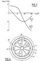
- FIG. 3 The evolution of the real part of the secondary field and the imaginary part of the secondary field, as a percentage of the primary field, for a given distance "a", as a function of the frequency, is shown in FIG. 3 attached.
- the curves in FIG. 3 make it possible to choose the frequency as a function of the sensitivity sought and of the geometry of the device.
- the system is placed on a robot 200 designed to continuously osculate the circumference of the pipe.
- the robot 200 preferably comprises several pads 210 fixed by generally radial arms 220 on a central pad holder 230, which pads 210 are applied along a circumference on the internal surface of the pipe.
- Each shoe 210 has one or more measurement sensors 110, 120.
- Each coil 110 carried by a shoe 210 is connected to the generator 114 placed on the shoe holder 230.
- each coil 120 carried by a pad 210 is connected to the measurement means 124 and to the storage and processing means 126 placed on the central pad holder 230.
- the generator 114 placed at the level of the pad holder 230 generates the electrical excitation signal continuously.
- slightly different frequencies are chosen for each of the devices so that simultaneous measurements can be made with all the devices located on the circumference.
- the robot 200 is moved slowly along the pipeline, for example of the order of 1m per second. The movement can be controlled manually or automatically by a motorized system.
- the present invention can also be applied for the control of pipes under load, on condition that the robot 200 can support it and for the control of bare steel pipes.
Landscapes
- Chemical & Material Sciences (AREA)
- Chemical Kinetics & Catalysis (AREA)
- Electrochemistry (AREA)
- Physics & Mathematics (AREA)
- Health & Medical Sciences (AREA)
- Life Sciences & Earth Sciences (AREA)
- Analytical Chemistry (AREA)
- Biochemistry (AREA)
- General Health & Medical Sciences (AREA)
- General Physics & Mathematics (AREA)
- Immunology (AREA)
- Pathology (AREA)
- Investigating Or Analyzing Materials By The Use Of Magnetic Means (AREA)
- Investigating Or Analyzing Materials By The Use Of Electric Means (AREA)
Applications Claiming Priority (2)
| Application Number | Priority Date | Filing Date | Title |
|---|---|---|---|
| FR9208941A FR2693797B1 (fr) | 1992-07-20 | 1992-07-20 | Système de contrôle de canalisations, notamment de canalisations en acier nu ou enrobé. |
| FR9208941 | 1992-07-20 |
Publications (1)
| Publication Number | Publication Date |
|---|---|
| EP0580485A1 true EP0580485A1 (de) | 1994-01-26 |
Family
ID=9432064
Family Applications (1)
| Application Number | Title | Priority Date | Filing Date |
|---|---|---|---|
| EP93401851A Withdrawn EP0580485A1 (de) | 1992-07-20 | 1993-07-19 | System zur Kontrolle von Kanalisation insbesondere aus Stahl mit oder ohne Ummantelung |
Country Status (4)
| Country | Link |
|---|---|
| EP (1) | EP0580485A1 (de) |
| JP (1) | JPH06317562A (de) |
| CA (1) | CA2100822A1 (de) |
| FR (1) | FR2693797B1 (de) |
Cited By (3)
| Publication number | Priority date | Publication date | Assignee | Title |
|---|---|---|---|---|
| FR2724019A1 (fr) * | 1994-08-31 | 1996-03-01 | Intercontrole Sa | Procede d'analyse numerique d'un signal, notamment pour controle par courants de foucault |
| WO2000042425A1 (en) * | 1999-01-13 | 2000-07-20 | Rock Solid Research Pty. Ltd. | A subsurface pipeline inspection probe |
| WO2002061412A3 (en) * | 2001-01-29 | 2004-07-08 | Pure Technologies Ltd | Electromagnetic analysis of concrete tensioning strands |
Families Citing this family (3)
| Publication number | Priority date | Publication date | Assignee | Title |
|---|---|---|---|---|
| DE69122801T2 (de) * | 1990-04-24 | 1997-03-20 | Nippon Denso Co | Eine Mehrzahl unabhängiger Dreiphasenwicklungen aufweisender Wechselstromgenerator |
| JP4982075B2 (ja) * | 2005-11-26 | 2012-07-25 | マークテック株式会社 | 渦電流探傷プローブ |
| JP5188088B2 (ja) * | 2007-03-30 | 2013-04-24 | 川崎重工業株式会社 | 減速機等の故障予知装置 |
Citations (4)
| Publication number | Priority date | Publication date | Assignee | Title |
|---|---|---|---|---|
| EP0260355A1 (de) * | 1985-03-29 | 1988-03-23 | Nippon Kokan Kabushiki Kaisha | Vorrichtung zur Erfassung von innerlichen Oberflächenfehlern jedes Rohres der eine Rohrleitung bildet |
| EP0370691A1 (de) * | 1988-11-16 | 1990-05-30 | Nnc Limited | Zerstörungsfreies Prüfverfahren mit Wirbelströmen |
| EP0392295A1 (de) * | 1989-04-13 | 1990-10-17 | Siemens Aktiengesellschaft | Wirbelstromprüfsonde zur Prüfung von Rohren eines Dampferzeugers |
| EP0449753A1 (de) * | 1990-03-26 | 1991-10-02 | Vallourec Industries | Verfahren und Vorrichtung zur Kontrolle von metallischen Rohren unter Verwendung von Wirbelströmen |
Family Cites Families (1)
| Publication number | Priority date | Publication date | Assignee | Title |
|---|---|---|---|---|
| JPS63124209A (ja) * | 1986-11-12 | 1988-05-27 | Sanyo Electric Co Ltd | 磁気ヘツドの特性検査方法 |
-
1992
- 1992-07-20 FR FR9208941A patent/FR2693797B1/fr not_active Expired - Fee Related
-
1993
- 1993-07-19 CA CA 2100822 patent/CA2100822A1/fr not_active Abandoned
- 1993-07-19 JP JP17837893A patent/JPH06317562A/ja active Pending
- 1993-07-19 EP EP93401851A patent/EP0580485A1/de not_active Withdrawn
Patent Citations (4)
| Publication number | Priority date | Publication date | Assignee | Title |
|---|---|---|---|---|
| EP0260355A1 (de) * | 1985-03-29 | 1988-03-23 | Nippon Kokan Kabushiki Kaisha | Vorrichtung zur Erfassung von innerlichen Oberflächenfehlern jedes Rohres der eine Rohrleitung bildet |
| EP0370691A1 (de) * | 1988-11-16 | 1990-05-30 | Nnc Limited | Zerstörungsfreies Prüfverfahren mit Wirbelströmen |
| EP0392295A1 (de) * | 1989-04-13 | 1990-10-17 | Siemens Aktiengesellschaft | Wirbelstromprüfsonde zur Prüfung von Rohren eines Dampferzeugers |
| EP0449753A1 (de) * | 1990-03-26 | 1991-10-02 | Vallourec Industries | Verfahren und Vorrichtung zur Kontrolle von metallischen Rohren unter Verwendung von Wirbelströmen |
Non-Patent Citations (1)
| Title |
|---|
| PATENT ABSTRACTS OF JAPAN vol. 12, no. 380 (P-769)12 Octobre 1988 & JP-A-63 124 209 ( SANYO ) 27 Mai 1988 * |
Cited By (8)
| Publication number | Priority date | Publication date | Assignee | Title |
|---|---|---|---|---|
| FR2724019A1 (fr) * | 1994-08-31 | 1996-03-01 | Intercontrole Sa | Procede d'analyse numerique d'un signal, notamment pour controle par courants de foucault |
| WO2000042425A1 (en) * | 1999-01-13 | 2000-07-20 | Rock Solid Research Pty. Ltd. | A subsurface pipeline inspection probe |
| US6573721B1 (en) | 1999-01-13 | 2003-06-03 | Rock Solid Research Pty. Ltd. | Time domain electromagnetic analysis and inspection system for conduits |
| US7042223B2 (en) | 1999-01-13 | 2006-05-09 | Rock Solid Research Pty. Ltd. | Time domain electromagnetic analysis and inspection system for conduits |
| WO2002061412A3 (en) * | 2001-01-29 | 2004-07-08 | Pure Technologies Ltd | Electromagnetic analysis of concrete tensioning strands |
| US6781369B2 (en) | 2001-01-29 | 2004-08-24 | Pure Technologies Ltd. | Electromagnetic analysis of concrete tensioning wires |
| US6791318B2 (en) | 2001-01-29 | 2004-09-14 | Pure Technologies Ltd. | Electromagnetic analysis of concrete tensioning wires |
| EP2458376A3 (de) * | 2001-01-29 | 2012-10-03 | Pure Technologies Ltd | Elektromagnetische Analyse von Betonspannungsdrähten |
Also Published As
| Publication number | Publication date |
|---|---|
| JPH06317562A (ja) | 1994-11-15 |
| FR2693797A1 (fr) | 1994-01-21 |
| CA2100822A1 (fr) | 1994-01-21 |
| FR2693797B1 (fr) | 1994-10-21 |
Similar Documents
| Publication | Publication Date | Title |
|---|---|---|
| EP0608230B1 (de) | Verfahren zum dynamischen kontaktlosen Messen einer Verschiebungs- oder Dielektrizitätskonstanten, mit Hilfe eines kapazitiven Sensors | |
| EP0176408B1 (de) | Verfahren und Messgerät zur akustischen Kontrolle eines mit einem Rohr ausgerüsteten Bohrlochs | |
| EP0215695A1 (de) | Verfahren und Vorrichtung zum Lokalisieren eines Objekts und Bestimmen seiner Orientierung im Raum | |
| FR2654214A1 (fr) | Formation d'image par courants de foucault utilisant une detection de difference de phase. | |
| JP2009539086A (ja) | 導電性基材上の導電性被膜の膜厚の決定方法 | |
| Lin et al. | Multiple reflection analysis of TDR signal for complex dielectric spectroscopy | |
| EP0290513B1 (de) | Verfahren zum feststellen der variationen der wandstärke eines elektrisch leitenden körpers | |
| FR2633971A1 (fr) | Dispositif et procede pour la determination dans un forage du pendage et de l'azimut d'une couche de discontinuite dans un milieu homogene | |
| EP0580485A1 (de) | System zur Kontrolle von Kanalisation insbesondere aus Stahl mit oder ohne Ummantelung | |
| FR2795521A1 (fr) | Procede et dispositif pour determiner la resistivite d'une formation traversee par un puits tube | |
| RU2733095C2 (ru) | Способ поиска трехмерных объектов методами геоэлектрики тм-поляризации | |
| CN102597791B (zh) | 用于测量电气设备的损耗因子的仪器和方法 | |
| FR2550628A1 (fr) | Procede et dispositif de mesure de la permeabilite initiale de materiaux ferrimagnetiques dans une large bande de frequences | |
| EP3067704B1 (de) | Vorrichtung zum messen eines elektrischen felds in einem leitenden medium, und kalibrierverfahren dieser vorrichtung | |
| CA2788259C (fr) | Procede d'estimation de defauts dans un objet et dispositif de mise en oeuvre | |
| WO2005096020A1 (en) | Method and apparatus for deriving a calibration filter for electromagnetic data | |
| EP0441074B1 (de) | Induktiver Sensor und Vorrichtung zum messen der Verschiebung eines mobilen Gegenstandes | |
| WO2000049398A1 (fr) | Procede et dispositif de mesure in situ de la distance entre deux elements donnes dans une conduite tubulaire | |
| EP0722096B1 (de) | Vorrichtung zur Kartierung eines Mediums durch Induktionsmessung | |
| EP1666923A1 (de) | Verfahren zur Lokalisierung beweglicher magnetischer Ziele | |
| FR3044780A1 (de) | ||
| EP0422985A1 (de) | Verfahren und Anlage zur Detektierung von Umkehrungen des erdmagnetischen Feldes durch Messungen in einem Bohrloch | |
| WO2002001145A1 (fr) | Procede de mesure d'epaisseur de paroi d'une aube creuse | |
| CH574105A5 (en) | Measurement of density and water content esp. for snow - by measuring permittivity using two different frequencies | |
| EP0200619B1 (de) | Einrichtung zum Messen des Niveaus von in einem Behälter enthaltenem elektrisch leitendem Material und ihre Anwendungen |
Legal Events
| Date | Code | Title | Description |
|---|---|---|---|
| PUAI | Public reference made under article 153(3) epc to a published international application that has entered the european phase |
Free format text: ORIGINAL CODE: 0009012 |
|
| AK | Designated contracting states |
Kind code of ref document: A1 Designated state(s): DE ES FR GB IT NL |
|
| 17P | Request for examination filed |
Effective date: 19940530 |
|
| 17Q | First examination report despatched |
Effective date: 19960201 |
|
| GRAG | Despatch of communication of intention to grant |
Free format text: ORIGINAL CODE: EPIDOS AGRA |
|
| GRAH | Despatch of communication of intention to grant a patent |
Free format text: ORIGINAL CODE: EPIDOS IGRA |
|
| STAA | Information on the status of an ep patent application or granted ep patent |
Free format text: STATUS: THE APPLICATION IS DEEMED TO BE WITHDRAWN |
|
| 18D | Application deemed to be withdrawn |
Effective date: 19970424 |