EP0580505A1 - Anpassungssystem zwischen einem Antennenstecker und der Buchse eines Funktelefons - Google Patents
Anpassungssystem zwischen einem Antennenstecker und der Buchse eines Funktelefons Download PDFInfo
- Publication number
- EP0580505A1 EP0580505A1 EP93401882A EP93401882A EP0580505A1 EP 0580505 A1 EP0580505 A1 EP 0580505A1 EP 93401882 A EP93401882 A EP 93401882A EP 93401882 A EP93401882 A EP 93401882A EP 0580505 A1 EP0580505 A1 EP 0580505A1
- Authority
- EP
- European Patent Office
- Prior art keywords
- antenna
- adaptation
- base
- housing
- connection
- Prior art date
- Legal status (The legal status is an assumption and is not a legal conclusion. Google has not performed a legal analysis and makes no representation as to the accuracy of the status listed.)
- Granted
Links
- 230000006978 adaptation Effects 0.000 title claims abstract description 38
- 238000003780 insertion Methods 0.000 claims abstract description 6
- 230000037431 insertion Effects 0.000 claims abstract description 6
- 230000007246 mechanism Effects 0.000 claims description 4
- 230000004913 activation Effects 0.000 claims description 3
- 238000000605 extraction Methods 0.000 claims description 3
- 239000002184 metal Substances 0.000 description 7
- 230000000295 complement effect Effects 0.000 description 4
- 238000012423 maintenance Methods 0.000 description 4
- 230000005540 biological transmission Effects 0.000 description 2
- 239000004020 conductor Substances 0.000 description 2
- 239000012212 insulator Substances 0.000 description 2
- 239000000470 constituent Substances 0.000 description 1
- 230000002542 deteriorative effect Effects 0.000 description 1
- 238000003754 machining Methods 0.000 description 1
- 239000000463 material Substances 0.000 description 1
- 238000000926 separation method Methods 0.000 description 1
Images

Classifications
-
- H—ELECTRICITY
- H01—ELECTRIC ELEMENTS
- H01Q—ANTENNAS, i.e. RADIO AERIALS
- H01Q1/00—Details of, or arrangements associated with, antennas
- H01Q1/12—Supports; Mounting means
- H01Q1/1207—Supports; Mounting means for fastening a rigid aerial element
- H01Q1/1214—Supports; Mounting means for fastening a rigid aerial element through a wall
-
- H—ELECTRICITY
- H01—ELECTRIC ELEMENTS
- H01Q—ANTENNAS, i.e. RADIO AERIALS
- H01Q1/00—Details of, or arrangements associated with, antennas
- H01Q1/08—Means for collapsing antennas or parts thereof
- H01Q1/088—Quick-releasable antenna elements
Definitions
- the field of the invention is that of adaptation systems between an antenna and a radio transmitter and / or receiver station. More specifically, the present invention relates to an adaptation system making it possible to connect any antenna to such a station.
- the station is for example a radiotelephone, and the present invention applies in particular to portable radiotelephones.
- a portable radiotelephone is in the form of a small-sized box to which is connected an antenna for transmitting and receiving radioelectric signals.
- the antenna comprises at one of its ends a plug cooperating with a complementary base fixed on the housing.
- the plug and the base provide both electrical contact and mechanical maintenance of the antenna to the housing and are manually separable to allow the antenna to be removed and thus facilitate the transport of the station and the antenna when not in use.
- An SMA type socket consists on the one hand of a female base, comprising a thread forming a mass and an internal conductor forming a core, and on the other hand of a male plug, comprising a nut capable of cooperating with this thread and a soul.
- the male plug is mounted at the end of an antenna and its cooperation with the base is ensured by screwing the nut onto the thread of the base.
- a socket allowing a high number of operations commonly called “subclic”
- the main disadvantage of this type of plug is that it is expensive and not widely used.
- the present invention aims in particular to overcome these drawbacks.
- a first objective of the invention is to provide an adaptation system between a radio transmission / reception station and an antenna allowing the user to mount any commercial antenna on his post.
- a second objective of the invention is to provide such a system which makes it possible to carry out a high number of maneuvers for securing-detaching the antenna from the station.
- an adaptation system between an antenna plug and a base of a radio transmitter and / or receiver station comprising a housing for receiving an adaptation element from the antenna plug to the base, this adaptation element comprising an electrical and mechanical connection end intended to cooperate with the antenna plug and an at least electrical connection means intended to cooperate with the base, this base being included inside the reception housing and coming into electrical contact with the connection means by axial insertion only of the adapter element in the housing, the adapter element being held in the housing by means of a manually actuated holding means so as to ensure an electrical connection between the antenna plug and the base when the antenna plug cooperates with the connection end.
- This system allows any antenna to be mounted on a specific station, the number of securing-detaching operations being high since the electrical contact between the base and the connection means is effected by axial insertion only of the element adaptation in the housing provided in the post. There is therefore no rotational movement to be made to electrically and mechanically connect the antenna to the station.
- connection means of the adaptation element is an axial connection means which penetrates axially into the base and the electrical connection end of the adaptation element is a screw connection cooperating with the plug. antenna, so that activation of the holding means allows simultaneous axial extraction of the antenna and the adapter element.
- connection means and the base constitute an MCX type socket.
- the antenna plug and the connection end constitute an SMA type socket.
- This guy socket is the most frequently used for connecting an antenna to a station and the user thus has a large choice of antenna type.
- the manually activatable holding means is constituted by a latching mechanism ensuring locking of the adaptation element in the housing. This ensures easy attachment and separation of the station and the antenna.
- the set is a portable radiotelephone.
- the invention also relates to an adaptation element and a station provided for such an adaptation system.
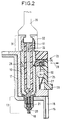
- Figures 1 and 2 show sections of a preferred embodiment of the system according to the invention.
- the system according to the invention is suitable for plugging an antenna of any type into a box of a radio transmitting and / or receiving station. It consists of an adapter element 10 comprising an end 11 of electrical and mechanical connection intended to cooperate with the plug of an antenna shown in FIG. 2.
- the adapter element 10 also includes an electrical connection means 12 intended to cooperate with a complementary base 13 located at the bottom of a receiving housing 14 formed in the station 15.
- a half-shell 16 of the station is shown, this half-shell being for example of plastic material.
- the housing 14 is for example cylindrical and has inner walls 17 of metal cooperating electrically and mechanically with the base 13.
- This base 13 comprises a central part 18 of metal, of female type, intended to come into electrical contact with a core 19 of the means of connection 12 of the adaptation element 10, this central part 18 being isolated, by an insulator 20, from a ground conductor 21 intended to come into electrical contact with metal teeth 22 of the means 12.
- the teeth 22 have a certain elasticity ensuring maintenance of the adaptation element 10 in the housing 14, when this element 10 is engaged in this housing 14. As will be seen later, this maintenance is mainly intended to ensure optimal electrical contact between the element 10 and the base 13.
- the adaptation element 10 is held in the housing 14 by means of a manually actuated holding means 23 which ensures an electrical connection between the antenna plug and the base when this antenna plug cooperates with the connection end.
- This holding means is here constituted by a lock 24 with beveled end, making it possible to insert the element 10 in the housing 14 without actuation of a lever 25.
- the lock cooperates, as shown in FIG. 2, with a groove 26 circular provided in the adaptation element 10.
- a leaf spring 27 integral with the lever 25 makes it possible to automatically recall the lock 24 in the position shown, this lock performing a movement of translation in a direction 28 when the user presses on the lower part 29 of the lever 25 or then engages the connection element 10 in the housing 14.
- the axis of rotation of the lever 25 is noted 30.
- the manually activatable holding means is constituted by a latching mechanism ensuring a locking of the adaptation element in the housing of the station, like that shown, the maneuvers of securing-detaching from the antenna, equipped with the adaptation element 10 are easy.
- connection means 12 and the base 13 constitute an MCX type socket.
- This type of plug is well known in the field of electrical cable connection, and allows a high number of operations (more than 4000 operations).
- the end 11 of electrical and mechanical connection is intended to cooperate with the plug 31 of an antenna 35.
- the embodiment shown corresponds to an SMA type socket, that is to say that the antenna plug comprises a nut 32 which is screwed onto the thread presented by the connection end 11 of the adapter element 10.
- This type of plug which does not allow a high number of operations is the most common for radiotelephone antennas.
- the adaptation element 10 may include other types of connection end, adapted to other types of antenna plugs.
- the connection end can for example be of the subclic, quarter-type turn, ...
- the base 13 and the connection means 12 may be of another type, the main thing being that the electrical contact between the element 10 and the base 13 is established inside of the housing 14 by simple insertion of the element 10 in the housing. It is for example possible to use metal blades arranged on either side in the housing 14, these blades being in electrical contact with conductive tracks disposed on the adaptation element 10. It will however be observed that the electrical connections made must be good quality since electrical signals have high frequencies.
- the core 33 of the antenna plug 31 enters a metal housing 34 (FIG. 1) connected to the core 19 of the connection means 12.
- the adaptation element 10 consists of a metal core 36 coated with an insulator 37 itself surrounded by a metal body 38 forming a mass and constituting the exterior of the element. The total length of this element is very reduced, of the order of 15 mm.
- the present invention applies to any type of radio transmitter and / or receiver station, and in particular to portable type radiotelephones. It allows any existing antenna to be attached to a specific station, the attachment achieved allowing a high number of operations. Its application to portable radiotelephones is advantageous insofar as their antennas are frequently removed, to facilitate their transport when not in use.
Landscapes
- Input Circuits Of Receivers And Coupling Of Receivers And Audio Equipment (AREA)
- Support Of Aerials (AREA)
- Telephone Set Structure (AREA)
- Fittings On The Vehicle Exterior For Carrying Loads, And Devices For Holding Or Mounting Articles (AREA)
- Connector Housings Or Holding Contact Members (AREA)
- Telephone Function (AREA)
- Details Of Aerials (AREA)
- Coupling Device And Connection With Printed Circuit (AREA)
- Transceivers (AREA)
Applications Claiming Priority (2)
| Application Number | Priority Date | Filing Date | Title |
|---|---|---|---|
| FR9209171 | 1992-07-24 | ||
| FR9209171A FR2694138B1 (fr) | 1992-07-24 | 1992-07-24 | Système d'adaptation entre une fiche d'antenne et un socle d'un radiotéléphone. |
Publications (2)
| Publication Number | Publication Date |
|---|---|
| EP0580505A1 true EP0580505A1 (de) | 1994-01-26 |
| EP0580505B1 EP0580505B1 (de) | 1997-09-03 |
Family
ID=9432243
Family Applications (1)
| Application Number | Title | Priority Date | Filing Date |
|---|---|---|---|
| EP93401882A Expired - Lifetime EP0580505B1 (de) | 1992-07-24 | 1993-07-21 | Anpassungssystem zwischen einem Antennenstecker und der Buchse eines Funktelefons |
Country Status (9)
| Country | Link |
|---|---|
| US (1) | US5603630A (de) |
| EP (1) | EP0580505B1 (de) |
| JP (1) | JPH06177624A (de) |
| AT (1) | ATE157818T1 (de) |
| AU (1) | AU668727B2 (de) |
| DE (1) | DE69313553T2 (de) |
| ES (1) | ES2105160T3 (de) |
| FR (1) | FR2694138B1 (de) |
| NZ (1) | NZ248121A (de) |
Cited By (5)
| Publication number | Priority date | Publication date | Assignee | Title |
|---|---|---|---|---|
| EP0710999A1 (de) * | 1993-09-20 | 1996-05-08 | Nec Corporation | Installationsstruktur für eine Aussen-Kommunikationseinrichtung |
| US5673886A (en) * | 1994-10-26 | 1997-10-07 | Nec Corporation | Installation structure of outdoor communication device |
| WO1998018654A1 (de) * | 1996-10-26 | 1998-05-07 | Robert Bosch Gmbh | Rundfunkempfänger |
| EP0875956A1 (de) * | 1994-10-25 | 1998-11-04 | Nec Corporation | Installationsstruktur für eine Aussen-Kommunikationseinrichtung |
| US6019327A (en) * | 1993-09-20 | 2000-02-01 | Nec Corporation | Installation structure of outdoor communication drive |
Families Citing this family (21)
| Publication number | Priority date | Publication date | Assignee | Title |
|---|---|---|---|---|
| DE9417946U1 (de) * | 1994-11-09 | 1995-01-05 | Fa. Carl Zeiss, 89520 Heidenheim | Zwischenstecker und Fotoapparat mit einem solchen Zwischenstecker |
| JPH09320690A (ja) * | 1996-05-31 | 1997-12-12 | Ricoh Co Ltd | Acアダプタ利用の装置 |
| ITVI980153A1 (it) * | 1998-08-11 | 2000-02-11 | Massimo Calearo | Antenna antifurto |
| US6166695A (en) * | 1998-10-02 | 2000-12-26 | Motorola, Inc. | Antenna detent and latching mechanism for a radiotelephone |
| JP3645106B2 (ja) * | 1998-11-12 | 2005-05-11 | 松下電器産業株式会社 | アンテナ装置及び該アンテナ装置を備えた携帯無線電子機器 |
| GB9907190D0 (en) * | 1999-03-30 | 1999-05-26 | Ganeshmoorthy David | Antenna connector bushing and coil assembly |
| WO2000065687A1 (en) * | 1999-04-28 | 2000-11-02 | The Whitaker Corporation | Antenna assembly adapted with an electrical plug |
| US6268836B1 (en) | 1999-04-28 | 2001-07-31 | The Whitaker Corporation | Antenna assembly adapted with an electrical plug |
| US6243041B1 (en) | 2000-04-24 | 2001-06-05 | Motorola, Inc. | Antenna indexing and retaining mechanism |
| US6317087B1 (en) | 2000-05-12 | 2001-11-13 | Motorola, Inc. | Antenna detent and latching system for satellite phones |
| FR2820887A1 (fr) * | 2001-02-15 | 2002-08-16 | Frank Fischer | L'antenne amplificatrice de radio telephone |
| KR100491537B1 (ko) * | 2002-07-11 | 2005-05-27 | 주식회사 선우커뮤니케이션 | 안테나 이득개선을 위한 휴대 단말기용 안테나연결커넥터 |
| TWI232673B (en) * | 2003-10-22 | 2005-05-11 | Benq Corp | Electronic device and lock device for locking module of electronic device |
| US7161538B2 (en) * | 2004-05-24 | 2007-01-09 | Amphenol-T&M Antennas | Multiple band antenna and antenna assembly |
| EP3084890A4 (de) | 2013-12-20 | 2017-07-05 | PPC Broadband, Inc. | Hochfrequenzabschirmung für mikrokoaxialkabelverbinder |
| JP6565654B2 (ja) * | 2015-12-11 | 2019-08-28 | 日立金属株式会社 | コネクタ及び端子接続構造 |
| WO2017139942A1 (zh) * | 2016-02-18 | 2017-08-24 | 林顺华 | 一种工业连接器和连接结构 |
| DE102017130005B3 (de) | 2017-12-14 | 2019-06-06 | Harting Electric Gmbh & Co. Kg | Steckverbinder |
| DE102017118918A1 (de) * | 2017-08-18 | 2019-02-21 | Harting Electric Gmbh & Co. Kg | Druckknopfverriegelung für ein Steckverbindergehäuse |
| US11493073B2 (en) | 2017-08-18 | 2022-11-08 | Harting Electric Gmbh & Co. Kg | Locking mechanism for a plug connector housing |
| TWI769669B (zh) * | 2021-01-19 | 2022-07-01 | 佳必琪國際股份有限公司 | 電連接器 |
Citations (5)
| Publication number | Priority date | Publication date | Assignee | Title |
|---|---|---|---|---|
| US4047779A (en) * | 1975-10-16 | 1977-09-13 | Afco Products Incorporated | Antenna couplings |
| FR2544552A1 (fr) * | 1983-04-12 | 1984-10-19 | Bellomayre Michel De | Support d'antenne auto-radio |
| FR2584871A3 (fr) * | 1985-07-09 | 1987-01-16 | Zendar Spa | Support fixe pour antennes |
| DE9105159U1 (de) * | 1991-04-26 | 1991-08-01 | Ulsmid, Franz, 8503 Altdorf | Ersatzantenne für Autoradio |
| EP0443172A1 (de) * | 1990-02-19 | 1991-08-28 | RICHARD HIRSCHMANN GMBH & CO. | Fahrzeugantenne |
Family Cites Families (8)
| Publication number | Priority date | Publication date | Assignee | Title |
|---|---|---|---|---|
| US2502303A (en) * | 1948-03-08 | 1950-03-28 | Cannon Electric Dev Company | Electrical connector |
| US3046513A (en) * | 1961-01-30 | 1962-07-24 | Gen Electric | Detachable electrical connector |
| GB1413673A (en) * | 1972-06-26 | 1975-11-12 | Bunker Ramo | Push-pull connector |
| JPS601503Y2 (ja) * | 1979-03-16 | 1985-01-16 | アルプス電気株式会社 | コネクタ |
| BE1000101A6 (fr) * | 1987-02-03 | 1988-03-22 | Anner Res And Dev Ltd | Connecteurs electriques. |
| US5158483A (en) * | 1988-01-11 | 1992-10-27 | Motorola, Inc. | Antenna connector and concealed test jack |
| US5015194A (en) * | 1989-03-17 | 1991-05-14 | Seas James A | Connector for antennas and coaxial cable |
| US5061940A (en) * | 1990-12-28 | 1991-10-29 | Blaese Herbert R | Antenna with quick disconnect whip |
-
1992
- 1992-07-24 FR FR9209171A patent/FR2694138B1/fr not_active Expired - Fee Related
-
1993
- 1993-07-12 NZ NZ248121A patent/NZ248121A/en unknown
- 1993-07-13 AU AU41874/93A patent/AU668727B2/en not_active Ceased
- 1993-07-21 EP EP93401882A patent/EP0580505B1/de not_active Expired - Lifetime
- 1993-07-21 DE DE69313553T patent/DE69313553T2/de not_active Expired - Fee Related
- 1993-07-21 AT AT93401882T patent/ATE157818T1/de not_active IP Right Cessation
- 1993-07-21 ES ES93401882T patent/ES2105160T3/es not_active Expired - Lifetime
- 1993-07-23 JP JP5183048A patent/JPH06177624A/ja active Pending
-
1995
- 1995-11-13 US US08/558,976 patent/US5603630A/en not_active Expired - Fee Related
Patent Citations (5)
| Publication number | Priority date | Publication date | Assignee | Title |
|---|---|---|---|---|
| US4047779A (en) * | 1975-10-16 | 1977-09-13 | Afco Products Incorporated | Antenna couplings |
| FR2544552A1 (fr) * | 1983-04-12 | 1984-10-19 | Bellomayre Michel De | Support d'antenne auto-radio |
| FR2584871A3 (fr) * | 1985-07-09 | 1987-01-16 | Zendar Spa | Support fixe pour antennes |
| EP0443172A1 (de) * | 1990-02-19 | 1991-08-28 | RICHARD HIRSCHMANN GMBH & CO. | Fahrzeugantenne |
| DE9105159U1 (de) * | 1991-04-26 | 1991-08-01 | Ulsmid, Franz, 8503 Altdorf | Ersatzantenne für Autoradio |
Cited By (6)
| Publication number | Priority date | Publication date | Assignee | Title |
|---|---|---|---|---|
| EP0710999A1 (de) * | 1993-09-20 | 1996-05-08 | Nec Corporation | Installationsstruktur für eine Aussen-Kommunikationseinrichtung |
| US5556066A (en) * | 1993-09-20 | 1996-09-17 | Nec Corporation | Installation structure of outdoor communication device |
| US6019327A (en) * | 1993-09-20 | 2000-02-01 | Nec Corporation | Installation structure of outdoor communication drive |
| EP0875956A1 (de) * | 1994-10-25 | 1998-11-04 | Nec Corporation | Installationsstruktur für eine Aussen-Kommunikationseinrichtung |
| US5673886A (en) * | 1994-10-26 | 1997-10-07 | Nec Corporation | Installation structure of outdoor communication device |
| WO1998018654A1 (de) * | 1996-10-26 | 1998-05-07 | Robert Bosch Gmbh | Rundfunkempfänger |
Also Published As
| Publication number | Publication date |
|---|---|
| US5603630A (en) | 1997-02-18 |
| ATE157818T1 (de) | 1997-09-15 |
| ES2105160T3 (es) | 1997-10-16 |
| NZ248121A (en) | 1995-12-21 |
| FR2694138A1 (fr) | 1994-01-28 |
| AU4187493A (en) | 1994-01-27 |
| JPH06177624A (ja) | 1994-06-24 |
| DE69313553D1 (de) | 1997-10-09 |
| DE69313553T2 (de) | 1998-01-15 |
| EP0580505B1 (de) | 1997-09-03 |
| FR2694138B1 (fr) | 1994-08-19 |
| AU668727B2 (en) | 1996-05-16 |
Similar Documents
| Publication | Publication Date | Title |
|---|---|---|
| EP0580505B1 (de) | Anpassungssystem zwischen einem Antennenstecker und der Buchse eines Funktelefons | |
| EP1143573A1 (de) | Koaxialer Verbinder | |
| EP2104963B1 (de) | Wasserdichte elektrische anschlussvorrichtung mit zwei konjugierten anschlusselementen | |
| EP0464767A1 (de) | Aus zwei über ein Gelenk und elektrisch verbundenen Elementen bestehendes Gerät | |
| EP1054479A1 (de) | Anordnung für eine elektrische Verbindung zwischen einer koaxialen Leitung und einer gedrückten Schaltungskarte | |
| FR2778500A1 (fr) | Antenne a plaque | |
| EP0663706A1 (de) | Mikrominiatur-Koaxialverbinder mit Schnappbefestigung | |
| EP2572406A1 (de) | Antennenschnittstelle für einen funkempfänger | |
| EP0678223A1 (de) | Koaxial hochfrequenz bauelement verbinder-umschalter | |
| EP1278224B1 (de) | Elektrische Verbindungsvorrichtung für zwei nebeneinander auf einer Schiene montierte elektrische Geräte | |
| EP0685911B1 (de) | Koaxiales elektrisches Verbinderelement mit Schalt-Funktion und elektrischer Verbinder mit einem derartigen Verbinderelement | |
| EP3512057A1 (de) | Elektrisches gerät, das drahtlos kommuniziert, und elektrischer schaltschrank, der ein solches elektrisches gerät umfasst | |
| FR2813998A1 (fr) | Dispositif comprenant un boitier et un connecteur pour liaison a un cable coaxial et procede de fabrication d'un tel dispositif | |
| EP0821837B1 (de) | Miniatur koaxialschaltsteckverbinder mit betätigungsstift und passiven kontaktfedern | |
| EP1147574B1 (de) | Koaxiale kabelverbindungseinrichtung | |
| FR2600217A1 (fr) | Connecteur de piquage cable coaxial et obturateur de substitution correspondant | |
| EP0643444A1 (de) | Elektrischer Kontakt mit elastischer Rückstellung | |
| EP1672740B1 (de) | Schnellverbindungsanschlussklemme für Schalter und Steckdosen | |
| EP3840154A1 (de) | Wasserdichtes elektrogerät | |
| EP2242158B1 (de) | Befestigungshaken für elektrische Geräte | |
| EP0654857B1 (de) | Elektrischen Steckanschluss mit ausklappbarer Verschlussblende | |
| FR2733351A1 (fr) | Connecteur interrupteur ou inverseur coaxial miniature a plongeur et lames de contact passives | |
| FR3069715A1 (fr) | Bloc multi-appareillages avec element d'appui anti porte-a-faux | |
| FR2688350A1 (fr) | Dispositif de connexion electrique et plus particulierement connecteur de charge. | |
| FR2678113A1 (fr) | Systeme de connecteur electrique. |
Legal Events
| Date | Code | Title | Description |
|---|---|---|---|
| PUAI | Public reference made under article 153(3) epc to a published international application that has entered the european phase |
Free format text: ORIGINAL CODE: 0009012 |
|
| AK | Designated contracting states |
Kind code of ref document: A1 Designated state(s): AT BE DE ES FR GB IT NL SE |
|
| 17P | Request for examination filed |
Effective date: 19940623 |
|
| RAP1 | Party data changed (applicant data changed or rights of an application transferred) |
Owner name: ALCATEL MOBILE COMMUNICATION FRANCE |
|
| GRAG | Despatch of communication of intention to grant |
Free format text: ORIGINAL CODE: EPIDOS AGRA |
|
| 17Q | First examination report despatched |
Effective date: 19961120 |
|
| GRAH | Despatch of communication of intention to grant a patent |
Free format text: ORIGINAL CODE: EPIDOS IGRA |
|
| GRAH | Despatch of communication of intention to grant a patent |
Free format text: ORIGINAL CODE: EPIDOS IGRA |
|
| GRAA | (expected) grant |
Free format text: ORIGINAL CODE: 0009210 |
|
| AK | Designated contracting states |
Kind code of ref document: B1 Designated state(s): AT BE DE ES FR GB IT NL SE |
|
| REF | Corresponds to: |
Ref document number: 157818 Country of ref document: AT Date of ref document: 19970915 Kind code of ref document: T |
|
| ITF | It: translation for a ep patent filed | ||
| GBT | Gb: translation of ep patent filed (gb section 77(6)(a)/1977) |
Effective date: 19970915 |
|
| REF | Corresponds to: |
Ref document number: 69313553 Country of ref document: DE Date of ref document: 19971009 |
|
| REG | Reference to a national code |
Ref country code: ES Ref legal event code: FG2A Ref document number: 2105160 Country of ref document: ES Kind code of ref document: T3 |
|
| PLBE | No opposition filed within time limit |
Free format text: ORIGINAL CODE: 0009261 |
|
| STAA | Information on the status of an ep patent application or granted ep patent |
Free format text: STATUS: NO OPPOSITION FILED WITHIN TIME LIMIT |
|
| 26N | No opposition filed | ||
| PGFP | Annual fee paid to national office [announced via postgrant information from national office to epo] |
Ref country code: GB Payment date: 20000614 Year of fee payment: 8 |
|
| PGFP | Annual fee paid to national office [announced via postgrant information from national office to epo] |
Ref country code: NL Payment date: 20000620 Year of fee payment: 8 |
|
| PGFP | Annual fee paid to national office [announced via postgrant information from national office to epo] |
Ref country code: AT Payment date: 20000622 Year of fee payment: 8 |
|
| PGFP | Annual fee paid to national office [announced via postgrant information from national office to epo] |
Ref country code: SE Payment date: 20000626 Year of fee payment: 8 |
|
| PGFP | Annual fee paid to national office [announced via postgrant information from national office to epo] |
Ref country code: FR Payment date: 20000629 Year of fee payment: 8 Ref country code: DE Payment date: 20000629 Year of fee payment: 8 |
|
| PGFP | Annual fee paid to national office [announced via postgrant information from national office to epo] |
Ref country code: BE Payment date: 20000704 Year of fee payment: 8 |
|
| PGFP | Annual fee paid to national office [announced via postgrant information from national office to epo] |
Ref country code: ES Payment date: 20000720 Year of fee payment: 8 |
|
| PG25 | Lapsed in a contracting state [announced via postgrant information from national office to epo] |
Ref country code: GB Free format text: LAPSE BECAUSE OF NON-PAYMENT OF DUE FEES Effective date: 20010721 Ref country code: AT Free format text: LAPSE BECAUSE OF NON-PAYMENT OF DUE FEES Effective date: 20010721 |
|
| PG25 | Lapsed in a contracting state [announced via postgrant information from national office to epo] |
Ref country code: SE Free format text: LAPSE BECAUSE OF NON-PAYMENT OF DUE FEES Effective date: 20010722 Ref country code: ES Free format text: LAPSE BECAUSE OF NON-PAYMENT OF DUE FEES Effective date: 20010722 |
|
| PG25 | Lapsed in a contracting state [announced via postgrant information from national office to epo] |
Ref country code: BE Free format text: LAPSE BECAUSE OF NON-PAYMENT OF DUE FEES Effective date: 20010731 |
|
| BERE | Be: lapsed |
Owner name: ALCATEL MOBILE COMMUNICATION FRANCE Effective date: 20010731 |
|
| PG25 | Lapsed in a contracting state [announced via postgrant information from national office to epo] |
Ref country code: NL Free format text: LAPSE BECAUSE OF NON-PAYMENT OF DUE FEES Effective date: 20020201 |
|
| EUG | Se: european patent has lapsed |
Ref document number: 93401882.1 |
|
| GBPC | Gb: european patent ceased through non-payment of renewal fee |
Effective date: 20010721 |
|
| PG25 | Lapsed in a contracting state [announced via postgrant information from national office to epo] |
Ref country code: FR Free format text: LAPSE BECAUSE OF NON-PAYMENT OF DUE FEES Effective date: 20020329 |
|
| NLV4 | Nl: lapsed or anulled due to non-payment of the annual fee |
Effective date: 20020201 |
|
| PG25 | Lapsed in a contracting state [announced via postgrant information from national office to epo] |
Ref country code: DE Free format text: LAPSE BECAUSE OF NON-PAYMENT OF DUE FEES Effective date: 20020501 |
|
| REG | Reference to a national code |
Ref country code: FR Ref legal event code: ST |
|
| REG | Reference to a national code |
Ref country code: ES Ref legal event code: FD2A Effective date: 20020810 |
|
| PG25 | Lapsed in a contracting state [announced via postgrant information from national office to epo] |
Ref country code: IT Free format text: LAPSE BECAUSE OF NON-PAYMENT OF DUE FEES;WARNING: LAPSES OF ITALIAN PATENTS WITH EFFECTIVE DATE BEFORE 2007 MAY HAVE OCCURRED AT ANY TIME BEFORE 2007. THE CORRECT EFFECTIVE DATE MAY BE DIFFERENT FROM THE ONE RECORDED. Effective date: 20050721 |