EP0580511A1 - Ceinture d'étanchéité de projectile flèche - Google Patents
Ceinture d'étanchéité de projectile flèche Download PDFInfo
- Publication number
- EP0580511A1 EP0580511A1 EP93401895A EP93401895A EP0580511A1 EP 0580511 A1 EP0580511 A1 EP 0580511A1 EP 93401895 A EP93401895 A EP 93401895A EP 93401895 A EP93401895 A EP 93401895A EP 0580511 A1 EP0580511 A1 EP 0580511A1
- Authority
- EP
- European Patent Office
- Prior art keywords
- sealing belt
- projectile
- housing
- belt
- belt according
- Prior art date
- Legal status (The legal status is an assumption and is not a legal conclusion. Google has not performed a legal analysis and makes no representation as to the accuracy of the status listed.)
- Granted
Links
- 238000007789 sealing Methods 0.000 claims description 32
- 239000000463 material Substances 0.000 claims description 12
- 229920001971 elastomer Polymers 0.000 claims description 6
- 239000000806 elastomer Substances 0.000 claims description 6
- 239000004033 plastic Substances 0.000 claims description 5
- 239000003999 initiator Substances 0.000 claims description 4
- -1 polytetrafluoroethylene Polymers 0.000 claims description 3
- 229920001343 polytetrafluoroethylene Polymers 0.000 claims description 3
- 239000004810 polytetrafluoroethylene Substances 0.000 claims description 3
- 239000004429 Calibre Substances 0.000 abstract 1
- 229920002292 Nylon 6 Polymers 0.000 description 8
- 239000007789 gas Substances 0.000 description 7
- 239000003380 propellant Substances 0.000 description 7
- 238000000926 separation method Methods 0.000 description 6
- 241000920340 Pion Species 0.000 description 5
- 230000000295 complement effect Effects 0.000 description 3
- 230000000977 initiatory effect Effects 0.000 description 3
- 238000003754 machining Methods 0.000 description 3
- 229920004482 WACKER® Polymers 0.000 description 2
- XAGFODPZIPBFFR-UHFFFAOYSA-N aluminium Chemical compound [Al] XAGFODPZIPBFFR-UHFFFAOYSA-N 0.000 description 2
- 229910052782 aluminium Inorganic materials 0.000 description 2
- 210000000003 hoof Anatomy 0.000 description 2
- RYGMFSIKBFXOCR-UHFFFAOYSA-N Copper Chemical compound [Cu] RYGMFSIKBFXOCR-UHFFFAOYSA-N 0.000 description 1
- 230000005540 biological transmission Effects 0.000 description 1
- 239000002131 composite material Substances 0.000 description 1
- 229910052802 copper Inorganic materials 0.000 description 1
- 239000010949 copper Substances 0.000 description 1
- 238000000605 extraction Methods 0.000 description 1
- 238000010304 firing Methods 0.000 description 1
- 229910001234 light alloy Inorganic materials 0.000 description 1
- 230000004807 localization Effects 0.000 description 1
- 238000012423 maintenance Methods 0.000 description 1
- 230000035515 penetration Effects 0.000 description 1
- 230000003014 reinforcing effect Effects 0.000 description 1
Images


Classifications
-
- F—MECHANICAL ENGINEERING; LIGHTING; HEATING; WEAPONS; BLASTING
- F42—AMMUNITION; BLASTING
- F42B—EXPLOSIVE CHARGES, e.g. FOR BLASTING, FIREWORKS, AMMUNITION
- F42B14/00—Projectiles or missiles characterised by arrangements for guiding or sealing them inside barrels, or for lubricating or cleaning barrels
- F42B14/02—Driving bands; Rotating bands
-
- F—MECHANICAL ENGINEERING; LIGHTING; HEATING; WEAPONS; BLASTING
- F42—AMMUNITION; BLASTING
- F42B—EXPLOSIVE CHARGES, e.g. FOR BLASTING, FIREWORKS, AMMUNITION
- F42B14/00—Projectiles or missiles characterised by arrangements for guiding or sealing them inside barrels, or for lubricating or cleaning barrels
- F42B14/06—Sub-calibre projectiles having sabots; Sabots therefor
- F42B14/067—Sealing aspects in sabots, e.g. sealing between individual segments of the sabots or sealing between the outer surface of the sabot and the inner surface of the barrel
Definitions
- the field of the present invention is that of sealing belts for arrow projectiles.
- An arrow projectile is composed in a known manner of an under-calibrated penetrator secured to a caliber shoe.
- the sabot is made up of several segments (generally three) which separate and release the indenter at the exit of the barrel of the weapon under the action of aerodynamic forces.
- this separation must be as symmetrical as possible so as not to disturb the indenter, which could affect the accuracy of the shot.
- the belt must therefore seal the propellant gases between the barrel of the weapon and the projectile and not disturb the separation of the sabot segments at the outlet of the barrel.
- the subject of the invention is a sealing belt for a shoe of an arrow projectile, shoe formed by several segments separated by joint planes, belt comprising at least one housing, in line with each joint plane, at the 'inside of which is disposed a pawn, belt characterized in that the pawn does not enter the shoe.
- a first advantage of such a configuration is to ensure a localization of the rupture of the belt at the level of the joint planes, during the separation of the segments of the sabot at the outlet of the barrel of the weapon.
- Another advantage is to ensure perfect sealing against propellant gases during the firing phase in the barrel of the weapon, in particular in the tubes having a high degree of wear.
- Non-stick means can be placed between the belt and the shoe segments.
- This non-stick means may consist of a plastic material of the polytetrafluoroethylene type deposited on the bottom and the sides of the annular groove receiving the belt.
- the pin has a compressive strength at least equal to that of the sealing belt and is preferably made of the same material as the sealing belt.
- the housing is produced in a direction substantially radial to the belt and has a substantially cylindrical shape.
- the housing has a substantially oblong shape, its greatest length being oriented along the joint plane.
- the housing does not open at the internal diameter of the belt and the housing-pin connection is provided by a sticky elastomer.
- the housing-pin connection is provided by a tight fit.
- the belt has two housings of which only the one located towards the front of the projectile is provided with a pin.
- the sealing belt comprises two housings each provided with a pin and a rupture initiation produced in line with each joint plane and on the front side of the projectile and which opens into the housing located furthest forward from the projectile.
- the initiation of rupture opens between the two housings by passing through the housing which is located furthest forward from the projectile.
- an arrow projectile 1 is conventionally constituted by a shoe 2 made of light alloy (such as aluminum) comprising several segments 2a, 2b, 2c (generally three), and in which is disposed a penetrator 3 of heavy material.
- a shoe 2 made of light alloy (such as aluminum) comprising several segments 2a, 2b, 2c (generally three), and in which is disposed a penetrator 3 of heavy material.
- the different segments of the shoe are held together by a hoop 4 located at the front of the projectile (along arrow C) and a belt 5 which is also intended to achieve, when fired, the seal against the propellant gases between the tube of the weapon and projectile.
- the front hoop 4 and the belt 5 are arranged in annular grooves 6 and 7 arranged on the shoe 2. Their establishment is carried out by overmolding of a plastic material such as polyamide 6, directly on the shoe.
- the belt 5 has an external diameter greater than the caliber of the barrel of the weapon.
- a seal 8 located on the rear of the projectile (according to arrow D) seals between the joint planes of the shoe segments and between the shoe and the indenter. This seal is obtained by injecting an elastomer on the assembled shoe.
- the belt has two housings 9 and 10 made in line with the joint plane 11 of the segments 2a and 2b.
- the two housings 9 and 10 are produced in a direction substantially radial to the belt and have a substantially cylindrical shape and a depth less than the thickness of the belt.
- the sealing belt of an arrow shell is generally put in place by overmolding. Overmolding takes place directly in the groove 7 made on the shoe 2, after placement on the bottom and sides of the groove of a plastic material preventing adhesion, for example a polytetrafluoroethylene.
- the belt thus has no attachment point to the shoe segments.
- Housing can only be produced by machining after overmolding. Also, in order not to risk damage to the segments, the housings do not open at the internal diameter of the belt and it There therefore remains at the bottom of the housings a material thickness (e) of the order of 0.1 mm which corresponds only to a machining tolerance of the housings.
- the realization of the housings can be carried out before fitting the belt on the shoe.
- the housings can cross the belt.
- the housings 9 and 10 constitute a means which locates the rupture of the belt in line with the joint plane 11 between the segments 2a and 2b during their separation at the outlet from the barrel of the weapon.
- Similar housings are provided in line with the parting lines between segments 2b and 2c and between segments 2c and 2a.
- a groove 15 of small width (of the order of 1 mm) is made in line with the joint plane 11.
- This groove made for example by machining using a large diameter saw burr (of the order 60 mm), passes in the two segments 2a and 2b of the shoe 2 and in the belt 5 coming slightly to open in the housing 9.
- the groove 15 is made on the front side of the arrow projectile (along arrow C) and constitutes a additional fracture initiator for the belt 5 which does not harm the sealing against propellant gases.
- pins 14 are put in place after the groove 15 has been made. These pins have a compressive strength equal to or greater than that of the sealing belt 5. material similar to that of the belt which is generally made of polyamide 6.
- the pins 14 may also be made of a material with high ductility suitable for creep under high pressure and non-aggressive for the barrel of the weapon such as copper, l aluminum or a plastic or composite material.
- the pins 14, bearing at the bottom of the housings 9 and 10 and of shape complementary to the latter, have in their upper part a recess (r), relative to the external diameter of the belt 5, such that they are all the same oversized relative to the caliber of the barrel of the weapon by a value between 0.1 and 1 mm.
- the overcalibration of the pins 14 causes, in the same way as the belt, a forcing in the barrel of the weapon which seals the propellant gases at the level of the housings.
- the pins 14 are advantageously held in their housing so that they can, from the start of the separation of the shoe segments, easily eject out of housings while remaining integral with the latter when handling the projectile.
- the pins 14 constitute a means of reinforcing the sealing belt at the level of the housings 9 and 10 and ensure perfect sealing against propellant gases. This prevents collapse of the belt at the housing 9 and 10 and a discontinuity in the seal.
- the belt 5 comprises a single recess 9 of oblong shape made in line with the joint plane 11 and oriented in the joint plane along its greatest length.
- a pin 14 of complementary shape In the housing 9 is disposed a pin 14 of complementary shape.
- the belt 5 comprises two housings 9 and 10 of substantially cylindrical shape produced in line with the joint plane 11 of the two segments 2a and 2b.
- the housing 9 comprises a pin 14 of complementary shape.
- the housing 10 remains empty, but the belt has a sufficient thickness of material behind the latter, which depends on the maximum pressure generated by the propellant gases, in order to prevent the belt from collapsing at the housing 10 at the time of shoot. For example, for a pressure less than or equal to 400 MPa, this thickness will be greater than 0.5 mm.
- the belt 5 comprises two housings 9 and 10 of substantially cylindrical shape produced in line with the joint plane 11 of the two segments 2a and 2b.
- At least one counter will be placed in the housing located furthest forward from the projectile (on the side designated in the figures by arrow C).
- This pin ensures the resistance of the belt to compressive forces during the passage of the forcing cone and this despite the presence of the initiation of rupture.
Landscapes
- Engineering & Computer Science (AREA)
- General Engineering & Computer Science (AREA)
- Adhesive Tapes (AREA)
- Packages (AREA)
- Package Frames And Binding Bands (AREA)
- Aiming, Guidance, Guns With A Light Source, Armor, Camouflage, And Targets (AREA)
- Portable Nailing Machines And Staplers (AREA)
- Gasket Seals (AREA)
Abstract
Description
- Le domaine de la présente invention est celui des ceintures d'étanchéité pour projectiles flèches.
- Un projectile flèche est composé de façon connue d'un pénétrateur sous-calibré solidaire d'un sabot au calibre.
- Le sabot est constitué de plusieurs segments (généralement trois) qui se séparent et libèrent le pénétrateur à la sortie du tube de l'arme sous l'action des efforts aérodynamiques.
- Un tel type de projectile est décrit par exemple dans le brevet FR2507765.
- Avec ces projectiles, il se pose le problème de la séparation des segments du sabot en particulier au niveau de la ceinture d'étanchéité.
- En effet cette séparation doit être aussi symétrique que possible afin de ne pas perturber le pénétrateur, ce qui risquerait d'affecter la précision du tir.
- La ceinture doit donc assurer l'étanchéité aux gaz propulsifs entre le tube de l'arme et le projectile et ne pas perturber la séparation des segments du sabot à la sortie du tube de l'arme.
- Afin de faciliter la rupture de la ceinture et de localiser celle-ci au droit des plans de joint, il est connu d'aménager sur cette dernière des amorces de rupture (par exemple des amincissements au droit des plans de joint inter segments).
- Il est également possible comme le propose le brevet EP0326653, de réaliser un encastrement de la ceinture sur le sabot au moyen de pions disposés de part et d'autre et à proximité immédiate des plans de joint.
- Mais de telles dispositions ne sont pas suffisamment fiables. Elles peuvent même nuire à l'ouverture symétrique du sabot. En effet, l'accrochage des pions va retarder cette ouverture en ne permettant pas la transmission des efforts dus à l'écartement des segments.
- C'est le but de l'invention que de proposer une ceinture d'étanchéité pour projectile flèche, présentant une résistance diminuée vis à vis des efforts d'extension générés lors de l'ouverture, tout en garantissant une étanchéité par une bonne résistance aux efforts de compression.
- Ainsi l'invention a pour objet une ceinture d'étanchéité pour un sabot d'un projectile flèche, sabot constitué par plusieurs segments séparés par des plans de joint, ceinture comprenant au moins un logement, au droit de chaque plan de joint, à l'intérieur duquel est disposé un pion, ceinture caractérisée en ce que le pion ne pénètre pas dans le sabot.
- Un premier avantage d'une telle configuration est d'assurer une localisation de la rupture de la ceinture au droit des plans de joint, lors de la séparation des segments du sabot à la sortie du tube de l'arme.
- Un autre avantage est d'assurer une parfaite étanchéité aux gaz propulsifs durant la phase de tir dans le tube de l'arme, notamment dans les tubes présentant un degré d'usure important.
- Un moyen anti-adhérent peut être déposé entre la ceinture et les segments du sabot. Ce moyen anti-adhérent pourra être constitué par une matière plastique du type polytétrafluoréthylène déposée sur le fond et les cotés de la gorge annulaire recevant la ceinture.
- Le pion présente une résistance à la compression au moins égale à celle de la ceinture d'étanchéité et est réalisé préférentiellement dans la même matière que la ceinture d'étanchéité.
- Selon un premier mode de réalisation, le logement est réalisé suivant une direction sensiblement radiale à la ceinture et présente une forme sensiblement cylindrique.
- Selon un deuxième mode de réalisation, le logement présente une forme sensiblement oblongue, sa plus grande longueur étant orientée suivant le plan de joint.
- De manière préférentielle, le logement ne débouche pas au niveau du diamètre interne de la ceinture et la liaison logement-pion est assurée par un élastomère collant.
- Selon une variante, la liaison logement-pion est assurée par un ajustement serré.
- Selon un troisième mode de réalisation, la ceinture comporte deux logements dont seul celui situé vers l'avant du projectile est pourvu d'un pion.
- En variante, la ceinture d'étanchéité comporte deux logements pourvus chacun d'un pion et une amorce de rupture réalisée au droit de chaque plan de joint et du coté avant du projectile et qui débouche dans le logement situé le plus en avant du projectile.
- Selon un quatrième mode de réalisation, l'amorce de rupture débouche entre les deux logements en traversant le logement qui est situé le plus en avant du projectile.
- L'invention sera mieux comprise à la lecture de la description de modes particuliers de réalisations, faite en référence aux dessins annexés dans lesquels:
- La figure 1 représente schématiquement en demi-vue un projectile flèche.
- La figure 2 représente une coupe d'un projectile flèche suivant la plan AA de la figure 1.
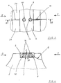
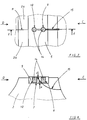
- La figure 3 représente schématiquement une vue de dessus partielle (suivant F de la figure 1) d'un sabot de projectile flèche équipé d'une ceinture selon un premier mode de réalisation de l'invention.
- La figure 4 est une coupe du sabot du projectile suivant le plan BB de la figure 3.
- La figure 5 représente schématiquement en vue partielle un sabot de projectile flèche équipé d'une ceinture selon un deuxième mode de réalisation de l'invention.
- La figure 6 représente schématiquement en vue partielle un sabot de projectile flèche équipé d'une ceinture selon un troisième mode de réalisation de l'invention.
- La figure 7 représente schématiquement une vue de dessus partielle d'un sabot de projectile flèche équipé d'une ceinture selon un quatrième mode de réalisation de l'invention.
- La figure 8 est une coupe du sabot du projectile suivant le plan EE de la figure 7.
- En se reportant aux figures 1 et 2, un projectile flèche 1 est constitué de façon classique d'un sabot 2 réalisé en alliage léger (tel l'aluminium) comprenant plusieurs segments 2a, 2b, 2c (généralement trois), et dans lequel est disposé un pénétrateur 3 en matériau lourd.
- Les différents segments du sabot sont maintenus solidaires par une frette 4 située à l'avant du projectile (suivant la flèche C) et une ceinture 5 qui est également destinée à réaliser lors du tir l'étanchéité aux gaz propulsifs entre le tube de l'arme et le projectile.
- La frette avant 4 et la ceinture 5 sont disposées dans des gorges annulaires 6 et 7 aménagées sur le sabot 2. Leur mise en place est effectuée par surmoulage d'une matière plastique telle le polyamide 6, directement sur le sabot. La ceinture 5 présente un diamètre externe supérieur au calibre du tube de l'arme.
- Un joint d'étanchéité 8 situé sur l'arrière du projectile (suivant la flèche D) assure l'étanchéité entre les plans de joints des segments du sabot et entre le sabot et le pénétrateur. Ce joint est obtenu par injection d'un élastomère sur le sabot assemblé.
- En référence aux figures 3 et 4, la ceinture comporte deux logements 9 et 10 réalisés au droit du plan de joint 11 des segments 2a et 2b. Les deux logements 9 et 10 sont réalisés dans une direction sensiblement radiale à la ceinture et présentent une forme sensiblement cylindrique et une profondeur inférieure à l'épaisseur de la ceinture.
- La ceinture d'étanchéité d'un obus flèche est généralement mise en place par surmoulage. Le surmoulage s'effectue directement dans la gorge 7 réalisée sur le sabot 2, après mise en place sur le fond et les côtés de la gorge d'une matière plastique évitant l'adhérence par exemple un polytétrafluoréthylène. La ceinture ne présente ainsi aucun point d'accrochage aux segments du sabot.
- La réalisation des logements ne peut être effectuée que par usinage après surmoulage. Aussi, afin de ne pas risquer un endommagement des segments, les logements ne débouchent pas au niveau du diamètre interne de la ceinture et il subsiste donc en fond de logements une épaisseur de matière (e) de l'ordre de 0,1 mm qui correspond uniquement à une tolérance d'usinage des logements.
- Mais on peut très bien concevoir une ceinture d'étanchéité mise en place sur le sabot par déformation. Dans ce cas de mise en oeuvre, la réalisation des logements peut être effectuée avant mise en place de la ceinture sur le sabot. Dans ce cas les logements peuvent traverser la ceinture.
- Les logements 9 et 10 constituent un moyen qui localise la rupture de la ceinture au droit du plan de joint 11 entre les segments 2a et 2b lors de leur séparation à la sortie du tube de l'arme.
- Des logements analogues sont prévus au droit des plans de joint entre les segments 2b et 2c et entre les segments 2c et 2a.
- Une rainure 15 de faible largeur (de l'ordre de 1 mm) est réalisée au droit du plan de joint 11. Cette rainure, effectuée par exemple par usinage à l'aide d'une fraise scie de grand diamètre (de l'ordre de 60 mm), passe dans les deux segments 2a et 2b du sabot 2 et dans la ceinture 5 en venant déboucher légèrement dans le logement 9. La rainure 15 est réalisée du coté avant du projectile flèche (suivant la flèche C) et constitue une amorce de rupture complémentaire pour la ceinture 5 qui ne nuit pas à l'étanchéité aux gaz propulsifs.
- Dans les deux logements 9 et 10 sont disposés des pions 14 mis en place après la réalisation de la rainure 15. Ces pions présentent une résistance à la compression égale ou supérieure à celle de la ceinture d'étanchéité 5. On pourra par exemple utiliser une matière similaire à celle de la ceinture qui est généralement réalisée en polyamide 6. Les pions 14 pourront être également réalisés dans une matière à haute ductilité apte au fluage sous haute pression et non agressive pour le tube de l'arme tel du cuivre, de l'aluminium non allié ou une matière plastique ou composite.
- Les pions 14, en appui au fond des logements 9 et 10 et de forme complémentaire à ces derniers, présentent en leur partie supérieure un retrait (r), par rapport au diamètre externe de la ceinture 5, tel qu'ils soient tout de même surcalibrés par rapport au calibre du tube de l'arme d'une valeur comprise entre 0,1 et 1 mm.
- Le surcalibrage des pions 14 provoque, au même titre que la ceinture, un forcement dans le tube de l'arme qui assure l'étanchéité aux gaz propulsifs au niveau des logements.
- Le retrait (r) de la partie supérieure des pions 14 est nécessaire afin de ne pas risquer un accrochage pouvant entraîner une extraction de ces derniers lors du passage de la ceinture dans le cône de forcement.
- Afin de ne pas faire obstacle à la localisation de la rupture, les pions 14 sont, de manière avantageuse, maintenus dans leur logement de telle manière qu'ils puissent, dès le début de la séparation des segments du sabot, s'éjecter facilement hors des logements tout en restant solidaires de ces derniers lors de manipulations du projectile.
- Pour cela, le maintien peut être réalisé de deux façons:
- soit les pions sont réalisés d'un diamètre permettant une pénétration à l'intérieur du logement par un léger forcement, par exemple de l'ordre de 0,01 à 0,4 mm au diamètre pour une ceinture et des pions réalisés en polyamide 6.
- soit les pions sont réalisés d'un diamètre légèrement inférieur à celui du logement, par exemple grâce à un jeu de l'ordre de 0,01 à 0,4 mm au diamètre pour une ceinture et des pions réalisés en polyamide 6, et on enduit le diamètre extérieur des pions d'un léger voile d'élastomère collant présentant une résistance à la traction inférieure à celle du matériau constitutif de la ceinture. Dans le cas d'une ceinture d'étanchéité réalisée en polyamide 6, l'élastomère collant présentera une résistance à la traction de l'ordre de 5 MPa comme par exemple l'élastomère E 41 commercialisé par la société Wacker sous la marque déposée "Elastosil".
- Pendant la phase de balistique intérieure, les pions 14 constituent un moyen de renfort de la ceinture d'étanchéité au niveau des logements 9 et 10 et assurent une parfaite étanchéité aux gaz propulsifs. On empêche de cette manière, un effondrement de la ceinture au niveau des logements 9 et 10 et une discontinuité de l'étanchéité.
- Selon un deuxième mode de réalisation représenté sur la figure 5, la ceinture 5 comporte un seul logement 9 de forme oblongue réalisé au droit du plan de joint 11 et orienté dans le plan de joint suivant sa plus grande longueur.
- Dans le logement 9 est disposé un pion 14 de forme complémentaire.
- Selon un troisième mode de réalisation représenté sur la figure 6, la ceinture 5 comporte deux logements 9 et 10 de forme sensiblement cylindrique réalisés au droit du plan de joint 11 des deux segments 2a et 2b. Une rainure 15, réalisée du coté avant du projectile (suivant la flèche C), vient déboucher dans le logement 9 et constitue une amorce de rupture.
- Afin de ne pas trop affaiblir la ceinture 5 au niveau de l'amorce de rupture 15, le logement 9 comporte un pion 14 de forme complémentaire. Le logement 10 reste vide, mais la ceinture présente en arrière de ce dernier une épaisseur de matière suffisante, qui dépend de la pression maximale engendrée par les gaz propulsifs, afin d'éviter un effondrement de la ceinture au niveau du logement 10 au moment du tir. Par exemple pour une pression inférieure ou égale à 400 MPa, cette épaisseur sera supérieure à 0,5 mm.
- Selon un quatrième mode de réalisation représenté sur les figures 7 et 8, la ceinture 5 comporte deux logements 9 et 10 de forme sensiblement cylindrique réalisés au droit du plan de joint 11 des deux segments 2a et 2b. Une rainure 15, réalisée du coté avant du projectile (suivant la flèche C), vient déboucher entre les deux logements en traversant le logement 9. L'amorce de rupture ainsi constituée est encore améliorée.
- A titre de variante, il est possible de réaliser une gorge 7 présentant des angles arrondis. Dans ce cas, il n'est pas nécessaire de disposer un moyen anti-adhérent entre la ceinture et la gorge du sabot.
- Il est également possible de prévoir plus de deux logements par plan de joint, de donner à ces derniers des formes différentes et de ne pas mettre de pion dans tous les logements suivant le niveau de pression auquel la ceinture est soumise.
- Dans tous les cas, au moins un pion sera disposé dans le logement situé le plus en avant du projectile (du coté désigné sur les figures par la flèche C).
- Ce pion assure la résistance de la ceinture aux efforts de compression lors du passage du cône de forcement et celà malgré la présence de l'amorce de rupture.
Claims (15)
Applications Claiming Priority (2)
| Application Number | Priority Date | Filing Date | Title |
|---|---|---|---|
| FR929209153A FR2694081B1 (fr) | 1992-07-24 | 1992-07-24 | Ceinture d'étanchéité de projectile flèche. |
| FR9209153 | 1992-07-24 |
Publications (2)
| Publication Number | Publication Date |
|---|---|
| EP0580511A1 true EP0580511A1 (fr) | 1994-01-26 |
| EP0580511B1 EP0580511B1 (fr) | 1996-09-25 |
Family
ID=9432228
Family Applications (1)
| Application Number | Title | Priority Date | Filing Date |
|---|---|---|---|
| EP93401895A Expired - Lifetime EP0580511B1 (fr) | 1992-07-24 | 1993-07-22 | Ceinture d'étanchéité de projectile flèche |
Country Status (4)
| Country | Link |
|---|---|
| EP (1) | EP0580511B1 (fr) |
| AT (1) | ATE143485T1 (fr) |
| DE (1) | DE69305018T2 (fr) |
| FR (1) | FR2694081B1 (fr) |
Cited By (3)
| Publication number | Priority date | Publication date | Assignee | Title |
|---|---|---|---|---|
| EP0703428A1 (fr) * | 1994-09-21 | 1996-03-27 | Rheinmetall Industrie GmbH | Sabot jetable pour projectiles sous-calibrés |
| EP1475600A1 (fr) * | 2003-05-07 | 2004-11-10 | Rheinmetall W & M GmbH | Sabot séparable |
| EP2221576A3 (fr) * | 2009-02-20 | 2013-07-24 | Rheinmetall Waffe Munition GmbH | Procédé d'application de points de rupture dans une bande de guidage et d'étanchéité en forme d'anneau d'un projectile sabot et outil destiné à l'exécution du procédé |
Families Citing this family (3)
| Publication number | Priority date | Publication date | Assignee | Title |
|---|---|---|---|---|
| FR2784177B1 (fr) | 1998-10-01 | 2005-09-16 | Giat Ind Sa | Sabot pour projectile sous calibre |
| DE19933184C2 (de) * | 1999-07-15 | 2002-11-21 | Rheinmetall W & M Gmbh | Unterkalibriges Geschoss |
| RU199619U1 (ru) * | 2020-05-26 | 2020-09-09 | Федеральное Государственное Бюджетное Образовательное Учреждение Высшего Образования «Новосибирский Государственный Технический Университет» | Осколочно-фугасный снаряд к гладкоствольному оружию |
Citations (4)
| Publication number | Priority date | Publication date | Assignee | Title |
|---|---|---|---|---|
| FR578477A (fr) * | 1923-05-24 | 1924-09-26 | Perfectionnements apportés aux projectiles d'artillerie | |
| US4040359A (en) * | 1976-05-14 | 1977-08-09 | The United States Of America As Represented By The Secretary Of The Army | Discarding frangible rotating band |
| FR2365098A1 (fr) * | 1976-09-20 | 1978-04-14 | Rheinmetall Gmbh | Projectile annulaire stabilise par giration |
| EP0326653A1 (fr) * | 1988-02-01 | 1989-08-09 | Rheinmetall GmbH | Sabot avec une ceinture de guidage |
-
1992
- 1992-07-24 FR FR929209153A patent/FR2694081B1/fr not_active Expired - Fee Related
-
1993
- 1993-07-22 EP EP93401895A patent/EP0580511B1/fr not_active Expired - Lifetime
- 1993-07-22 AT AT93401895T patent/ATE143485T1/de not_active IP Right Cessation
- 1993-07-22 DE DE69305018T patent/DE69305018T2/de not_active Expired - Fee Related
Patent Citations (4)
| Publication number | Priority date | Publication date | Assignee | Title |
|---|---|---|---|---|
| FR578477A (fr) * | 1923-05-24 | 1924-09-26 | Perfectionnements apportés aux projectiles d'artillerie | |
| US4040359A (en) * | 1976-05-14 | 1977-08-09 | The United States Of America As Represented By The Secretary Of The Army | Discarding frangible rotating band |
| FR2365098A1 (fr) * | 1976-09-20 | 1978-04-14 | Rheinmetall Gmbh | Projectile annulaire stabilise par giration |
| EP0326653A1 (fr) * | 1988-02-01 | 1989-08-09 | Rheinmetall GmbH | Sabot avec une ceinture de guidage |
Cited By (4)
| Publication number | Priority date | Publication date | Assignee | Title |
|---|---|---|---|---|
| EP0703428A1 (fr) * | 1994-09-21 | 1996-03-27 | Rheinmetall Industrie GmbH | Sabot jetable pour projectiles sous-calibrés |
| EP1475600A1 (fr) * | 2003-05-07 | 2004-11-10 | Rheinmetall W & M GmbH | Sabot séparable |
| EP2221576A3 (fr) * | 2009-02-20 | 2013-07-24 | Rheinmetall Waffe Munition GmbH | Procédé d'application de points de rupture dans une bande de guidage et d'étanchéité en forme d'anneau d'un projectile sabot et outil destiné à l'exécution du procédé |
| KR101531427B1 (ko) * | 2009-02-20 | 2015-07-06 | 라인메탈 바페 뮤니션 게엠베하 | 새보우 케이지 발사체의 링형 지지 및 밀봉 밴드 내에 설정 파괴점을 형성하는 방법 및 이 방법을 실시하는 작업 공구 |
Also Published As
| Publication number | Publication date |
|---|---|
| ATE143485T1 (de) | 1996-10-15 |
| EP0580511B1 (fr) | 1996-09-25 |
| DE69305018T2 (de) | 1997-02-06 |
| FR2694081A1 (fr) | 1994-01-28 |
| FR2694081B1 (fr) | 1994-09-30 |
| DE69305018D1 (de) | 1996-10-31 |
Similar Documents
| Publication | Publication Date | Title |
|---|---|---|
| CA1333544C (fr) | Munition pour armes a feu, notamment munition de chasse | |
| EP0906556A1 (fr) | Projectile non letal | |
| FR2527763A1 (fr) | Element de propulsion pour un projectile sous-calibre | |
| EP0307307B1 (fr) | Bague de liaison entre un projectile et une douille | |
| EP0491614B1 (fr) | Ceinture dérapante pour projectile de tout calibre et son procédé de réalisation | |
| EP2336711A1 (fr) | Dispositif de lancement pour projectile d'artillerie sous calibré | |
| EP0580511B1 (fr) | Ceinture d'étanchéité de projectile flèche | |
| EP0267090B1 (fr) | Grenade à fusil | |
| FR2806789A1 (fr) | Tube allumeur pour une munition d'artillerie | |
| EP0471617A1 (fr) | Ceinture d'étanchéité pour projectile flèche | |
| EP0728293B1 (fr) | Balle de chasse a double penetration et a portee reduite | |
| EP3489617B1 (fr) | Projectile | |
| EP1103780B1 (fr) | Dispositif de liaison entre une douille et un projectile et procédé de montage d'une ceinture sur un projectile mettant en oeuvre un tel dispositif | |
| EP0471616A1 (fr) | Dispositif d'arrêt en rotation entre un barreau et un sabot | |
| EP1693646B1 (fr) | Ceinture d'étanchéité pour projectile d'artillerie | |
| EP4025865A1 (fr) | Obus anti-aérien pour munition télescopée à double déverrouillage | |
| FR2633712A1 (fr) | Perfectionnement apporte aux munitions a etuis rechargeables | |
| FR2880680A1 (fr) | Munition d'entrainement et d'intervention | |
| FR2507765A1 (fr) | Procede et dispositif de tir d'une munition fleche a l'aide d'un tube raye | |
| CA2176029C (fr) | Balle de chasse a double penetration et a portee reduite | |
| EP1023573B1 (fr) | Lanceur a etancheite amelioree pour munitions du type comportant un lanceur associe a un sous-projectile | |
| EP1431701A1 (fr) | Munition sans douille et procédé de montage d'une telle munition | |
| FR2844589A1 (fr) | Projectile sous calibre a piece de guidage rapportee | |
| FR2677749A1 (fr) | Dispositif a projectiles comportant deux projectiles a effet cinetique sous-calibres. | |
| EP1586852A1 (fr) | Munition sans douille et procede de montage d'une telle munition |
Legal Events
| Date | Code | Title | Description |
|---|---|---|---|
| PUAI | Public reference made under article 153(3) epc to a published international application that has entered the european phase |
Free format text: ORIGINAL CODE: 0009012 |
|
| AK | Designated contracting states |
Kind code of ref document: A1 Designated state(s): AT BE DE FR GB GR IT NL SE |
|
| 17P | Request for examination filed |
Effective date: 19940225 |
|
| 17Q | First examination report despatched |
Effective date: 19950627 |
|
| GRAG | Despatch of communication of intention to grant |
Free format text: ORIGINAL CODE: EPIDOS AGRA |
|
| GRAH | Despatch of communication of intention to grant a patent |
Free format text: ORIGINAL CODE: EPIDOS IGRA |
|
| GRAH | Despatch of communication of intention to grant a patent |
Free format text: ORIGINAL CODE: EPIDOS IGRA |
|
| GRAA | (expected) grant |
Free format text: ORIGINAL CODE: 0009210 |
|
| AK | Designated contracting states |
Kind code of ref document: B1 Designated state(s): AT BE DE FR GB GR IT NL SE |
|
| PG25 | Lapsed in a contracting state [announced via postgrant information from national office to epo] |
Ref country code: GR Free format text: LAPSE BECAUSE OF FAILURE TO SUBMIT A TRANSLATION OF THE DESCRIPTION OR TO PAY THE FEE WITHIN THE PRESCRIBED TIME-LIMIT Effective date: 19960925 Ref country code: AT Effective date: 19960925 |
|
| REF | Corresponds to: |
Ref document number: 143485 Country of ref document: AT Date of ref document: 19961015 Kind code of ref document: T |
|
| ITF | It: translation for a ep patent filed | ||
| GBT | Gb: translation of ep patent filed (gb section 77(6)(a)/1977) |
Effective date: 19960925 |
|
| REF | Corresponds to: |
Ref document number: 69305018 Country of ref document: DE Date of ref document: 19961031 |
|
| PG25 | Lapsed in a contracting state [announced via postgrant information from national office to epo] |
Ref country code: SE Effective date: 19961225 |
|
| PG25 | Lapsed in a contracting state [announced via postgrant information from national office to epo] |
Ref country code: BE Free format text: LAPSE BECAUSE OF NON-PAYMENT OF DUE FEES Effective date: 19970731 |
|
| PLBE | No opposition filed within time limit |
Free format text: ORIGINAL CODE: 0009261 |
|
| STAA | Information on the status of an ep patent application or granted ep patent |
Free format text: STATUS: NO OPPOSITION FILED WITHIN TIME LIMIT |
|
| 26N | No opposition filed | ||
| BERE | Be: lapsed |
Owner name: GIAT INDUSTRIES Effective date: 19970731 |
|
| PG25 | Lapsed in a contracting state [announced via postgrant information from national office to epo] |
Ref country code: NL Free format text: LAPSE BECAUSE OF NON-PAYMENT OF DUE FEES Effective date: 19980201 |
|
| NLV4 | Nl: lapsed or anulled due to non-payment of the annual fee |
Effective date: 19980201 |
|
| REG | Reference to a national code |
Ref country code: GB Ref legal event code: IF02 |
|
| PG25 | Lapsed in a contracting state [announced via postgrant information from national office to epo] |
Ref country code: IT Free format text: LAPSE BECAUSE OF NON-PAYMENT OF DUE FEES Effective date: 20050722 |
|
| PGFP | Annual fee paid to national office [announced via postgrant information from national office to epo] |
Ref country code: GB Payment date: 20070627 Year of fee payment: 15 |
|
| GBPC | Gb: european patent ceased through non-payment of renewal fee |
Effective date: 20080722 |
|
| PG25 | Lapsed in a contracting state [announced via postgrant information from national office to epo] |
Ref country code: GB Free format text: LAPSE BECAUSE OF NON-PAYMENT OF DUE FEES Effective date: 20080722 |
|
| PGFP | Annual fee paid to national office [announced via postgrant information from national office to epo] |
Ref country code: FR Payment date: 20090721 Year of fee payment: 17 |
|
| PGFP | Annual fee paid to national office [announced via postgrant information from national office to epo] |
Ref country code: DE Payment date: 20090707 Year of fee payment: 17 |
|
| REG | Reference to a national code |
Ref country code: FR Ref legal event code: ST Effective date: 20110331 |
|
| PG25 | Lapsed in a contracting state [announced via postgrant information from national office to epo] |
Ref country code: DE Free format text: LAPSE BECAUSE OF NON-PAYMENT OF DUE FEES Effective date: 20110201 |
|
| REG | Reference to a national code |
Ref country code: DE Ref legal event code: R119 Ref document number: 69305018 Country of ref document: DE Effective date: 20110201 |
|
| PG25 | Lapsed in a contracting state [announced via postgrant information from national office to epo] |
Ref country code: FR Free format text: LAPSE BECAUSE OF NON-PAYMENT OF DUE FEES Effective date: 20100802 |