EP0580573B1 - Verbesserte vorrichtung für unterwasserausgrabung - Google Patents
Verbesserte vorrichtung für unterwasserausgrabung Download PDFInfo
- Publication number
- EP0580573B1 EP0580573B1 EP91908095A EP91908095A EP0580573B1 EP 0580573 B1 EP0580573 B1 EP 0580573B1 EP 91908095 A EP91908095 A EP 91908095A EP 91908095 A EP91908095 A EP 91908095A EP 0580573 B1 EP0580573 B1 EP 0580573B1
- Authority
- EP
- European Patent Office
- Prior art keywords
- propeller
- hollow body
- water
- vanes
- excavation apparatus
- Prior art date
- Legal status (The legal status is an assumption and is not a legal conclusion. Google has not performed a legal analysis and makes no representation as to the accuracy of the status listed.)
- Expired - Lifetime
Links
- 238000009412 basement excavation Methods 0.000 title claims abstract description 33
- XLYOFNOQVPJJNP-UHFFFAOYSA-N water Substances O XLYOFNOQVPJJNP-UHFFFAOYSA-N 0.000 claims abstract description 63
- 238000006243 chemical reaction Methods 0.000 claims description 11
- 239000000463 material Substances 0.000 claims description 7
- 238000007599 discharging Methods 0.000 claims description 2
- 239000008400 supply water Substances 0.000 claims description 2
- 238000011144 upstream manufacturing Methods 0.000 claims description 2
- 238000009434 installation Methods 0.000 abstract 2
- 238000005553 drilling Methods 0.000 description 5
- 230000008878 coupling Effects 0.000 description 3
- 238000010168 coupling process Methods 0.000 description 3
- 238000005859 coupling reaction Methods 0.000 description 3
- 238000005520 cutting process Methods 0.000 description 2
- 230000000694 effects Effects 0.000 description 2
- 239000012530 fluid Substances 0.000 description 2
- 230000003068 static effect Effects 0.000 description 2
- 229910000831 Steel Inorganic materials 0.000 description 1
- 238000001816 cooling Methods 0.000 description 1
- 230000001066 destructive effect Effects 0.000 description 1
- 238000005188 flotation Methods 0.000 description 1
- 238000000034 method Methods 0.000 description 1
- 239000004576 sand Substances 0.000 description 1
- 239000010959 steel Substances 0.000 description 1
Images


Classifications
-
- E—FIXED CONSTRUCTIONS
- E02—HYDRAULIC ENGINEERING; FOUNDATIONS; SOIL SHIFTING
- E02F—DREDGING; SOIL-SHIFTING
- E02F3/00—Dredgers; Soil-shifting machines
- E02F3/04—Dredgers; Soil-shifting machines mechanically-driven
- E02F3/88—Dredgers; Soil-shifting machines mechanically-driven with arrangements acting by a sucking or forcing effect, e.g. suction dredgers
- E02F3/8858—Submerged units
-
- E—FIXED CONSTRUCTIONS
- E02—HYDRAULIC ENGINEERING; FOUNDATIONS; SOIL SHIFTING
- E02D—FOUNDATIONS; EXCAVATIONS; EMBANKMENTS; UNDERGROUND OR UNDERWATER STRUCTURES
- E02D1/00—Investigation of foundation soil in situ
- E02D1/02—Investigation of foundation soil in situ before construction work
- E02D1/04—Sampling of soil
-
- E—FIXED CONSTRUCTIONS
- E02—HYDRAULIC ENGINEERING; FOUNDATIONS; SOIL SHIFTING
- E02F—DREDGING; SOIL-SHIFTING
- E02F3/00—Dredgers; Soil-shifting machines
- E02F3/04—Dredgers; Soil-shifting machines mechanically-driven
- E02F3/88—Dredgers; Soil-shifting machines mechanically-driven with arrangements acting by a sucking or forcing effect, e.g. suction dredgers
-
- E—FIXED CONSTRUCTIONS
- E02—HYDRAULIC ENGINEERING; FOUNDATIONS; SOIL SHIFTING
- E02F—DREDGING; SOIL-SHIFTING
- E02F3/00—Dredgers; Soil-shifting machines
- E02F3/04—Dredgers; Soil-shifting machines mechanically-driven
- E02F3/88—Dredgers; Soil-shifting machines mechanically-driven with arrangements acting by a sucking or forcing effect, e.g. suction dredgers
- E02F3/90—Component parts, e.g. arrangement or adaptation of pumps
- E02F3/92—Digging elements, e.g. suction heads
- E02F3/9206—Digging devices using blowing effect only, like jets or propellers
-
- E—FIXED CONSTRUCTIONS
- E02—HYDRAULIC ENGINEERING; FOUNDATIONS; SOIL SHIFTING
- E02F—DREDGING; SOIL-SHIFTING
- E02F5/00—Dredgers or soil-shifting machines for special purposes
- E02F5/003—Dredgers or soil-shifting machines for special purposes for uncovering conduits
-
- Y—GENERAL TAGGING OF NEW TECHNOLOGICAL DEVELOPMENTS; GENERAL TAGGING OF CROSS-SECTIONAL TECHNOLOGIES SPANNING OVER SEVERAL SECTIONS OF THE IPC; TECHNICAL SUBJECTS COVERED BY FORMER USPC CROSS-REFERENCE ART COLLECTIONS [XRACs] AND DIGESTS
- Y10—TECHNICAL SUBJECTS COVERED BY FORMER USPC
- Y10S—TECHNICAL SUBJECTS COVERED BY FORMER USPC CROSS-REFERENCE ART COLLECTIONS [XRACs] AND DIGESTS
- Y10S173/00—Tool driving or impacting
- Y10S173/01—Operable submerged in liquid
Definitions
- This invention relates to underwater excavation apparatus and is particularly, although not exclusively, applicable to underwater excavation apparatus as described and illustrated in EP-A-0289520.
- EP-A-0289520 describes and illustrates an underwater excavation apparatus comprising a tube in which a propeller is mounted which, when energised, produces an unrestricted flow of water of sufficient volume and velocity to carry away sea-bed material.
- the propeller is driven by a motor mounted in the steel tube and connected via an umbilical to a power supply at the surface.
- US-A-2 705 051 discloses a fluid driven propeller having a hub carrying a plurality of blades each of which has twin internal ducts having outlet ends disposed on the trailing blade edges and a single duct to which the twin ducts are connected and opening internally the propeller hub.
- the walls of the ducts are formed as turbine rotor surfaces so that the propeller can be driven by the turbine effect produced by fluid under pressure applied through the hub to the rotor surfaces provided by the duct walls.
- the propeller is intended for marine propulsion or as a low pressure pump, as a turbine screw driven by compressed air, as an aeroplane propeller, as a cooling fan or as a small size reaction turbine.
- This invention provides underwater excavation apparatus comprising a hollow body having an inlet to receive water, an outlet for discharging water, and a power driven propeller having a plurality of blades mounted for rotation at a location in the hollow body to draw water through the inlet and deliver a stream of water through the outlet; wherein jet means are provided on the propeller blades and means are provided to supply water under pressure to the jet means to cause the propeller to rotate and thereby deliver a flow of water through the outlet for displacing material on the seabed; and wherein and in that the hollow body has an encircling slit at the location of the propeller, an annular wall is mounted on the outer side of the hollow body to extend on either side of the slit to define an annular chamber around the hollow body and said jet means are located at tips of the propeller blades to project through the annular slit into said annular chamber and face tangentially with respect to the blades to produce water jets which react on the water contained within the annular chamber and thereby cause the propeller to turn within the
- Preferably means are provided for feeding water under pressure from the centre of the propeller to the jet means.
- the blades of the propeller may be hollow to provide passages extending from the centre of the propeller to the blade tips and said jet means at the blade tips are in communication with the passages.
- vanes may be disposed at spaced locations around the outer periphery of the body between the body and the annular wall and extending to either side of said slit in the hollow body, the vanes having slots extending into the vanes from the slit in the hollow body and the jets on the blades of the propeller extend outwardly therefrom in alignment with the slots in the external vanes, the jets being angled to face tangentially of the propeller and to impinge on the vanes so as to create a reaction force on the vanes which acts to oppose any tendency of the hollow body to rotate in the same direction as the propeller.
- the vanes may be mounted on the hollow body on both sides of said annular slit and the annular wall is mounted on the outer peripheries of the vanes.
- the propeller is mounted on a shaft supported in spaced bearing hubs mounted in the hollow body, the shaft being hollow to provide a passageway for a supply of high pressure water to the jets on the propeller blades.
- bearing hubs may be mounted on radially extending fixed vanes extending to the wall of the hollow body upstream and/or downstream of the propeller, the vanes lying in planes extending along the hollow body to direct flow lengthwise along the hollow body and reduce swirl resulting from the action of the propeller.
- the inlet to the hollow body may face in the same direction as the outlet whereby the reaction in the body in ejecting water through the outlet is countered by the reaction in drawing in water.
- the inlet may encircle the hollow body adjacent one end thereof and means may be provided to reverse the direction of flow between the inlet and hollow body whereby the direction of flow into the inlet is opposite to the direction of flow from the outlet.
- buoyancy means may be provided to render the apparatus buoyant underwater and anchor means are provided for holding the hollow body with the outlet facing downwardly to act on the sea-bed.
- the apparatus of any of the above arrangements may be used in combination with a drill string in which the hollow body of the apparatus is mounted at the lower end of the drill string to displace material on the seabed below the drill string.
- the drill string may include a high pressure water supply extending axially down the centre of the drill string and connected to the water jet means on the propeller of the excavation means to rotate that propeller and thereby creates the flow of water through the hollow body of the excavation apparatus directed at the seabed below the drill string.
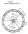
- FIGS. 1 and 2 of the drawings illustrate an underwater excavation apparatus not embodying the present invention by way of background information.
- the apparatus comprises a hollow cylindrical tube 10 disposed with its axis extending vertically and having an upper, inlet end 11 through which water may be drawn into the tube and a lower outlet end 12 from which water may discharge from the tube.
- Each set of vanes may comprise four vanes.
- the vanes 15,16 lie in planes extending lengthwise of the tube for a further purpose to be described later.
- a shaft 17 extends between and is mounted for rotation in the bearing housings 13,14 to carry a propeller indicated at 18 disposed on the shaft between the housings.
- the propeller comprises a hub 19 secured to the shaft and four (or more) outwardly extending blades 20.
- a sleeve 21 encircles and is secured to the tips 22 of the blades, the sleeve forming a narrow annular gap 23 with the inner side of the tube 10.
- the shaft 17 has an upper end 24 which projects through a bearing housing 13 and an umbilical 25 carrying a high pressure water supply is connected to the upper end of the shaft by means of a high pressure water slip ring 26 to allow the shaft to rotate with respect to the umbilical.
- the shaft 17 is formed with a throughway 27 extending from its upper end 24 to the region located within the propeller hub 19.
- the throughway 27 opens into a manifold 28 formed in the shaft connected to radial passages extending through the wall of the hub 19 to passages 29 extending outwardly through the propeller blades 20.
- the passages 29 are angled forwardly in a clockwise direction as seen from above (in Figure 2) and terminate in forwardly and outwardly angled jets 30 in the wall of the sleeve 21.
- the jets from the propeller blade tips 30 react against a ring of fixed reaction blades or vanes 31 mounted in the tube disposed around the perimeter of the sleeve 21.
- the blades 31 extend lengthwise of the tube 10, and taper towards the outlet end of the tube.
- the vanes are concavely curved towards the jets 30 and as best seen in Figure 2 chambers are formed between adjacent vanes within the tube 10 and around the sleeve 21 into which the jets discharge successively to maximise the reaction of the jets on the blades.
- the discharge is used to act on the seabed to displace loose material such as sand or silt forming the seabed for creating a pipeline trench, or filling a trench in or any other similar purpose.
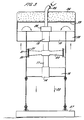
- the tube 11 has an opened topped inlet so that water is drawn in to the tube and discharged from the tube in the same direction.
- the inlet to the tube is formed by a downwardly facing annular inlet 38 into the tube around the upper end thereof so that water is drawn into the tube in the opposite direction from that in which it is discharged whereby the reaction of drawing water in counteracts the discharge thrusts.
- the arrangement of the annular inlet is provided by a top hat shaped upper end wall 39 extending over the upper end of the tube to provide a downwardly facing annular inlet around the outer periphery of the tube and to cause water flow to reverse in passing from the inlet into the upper end of the tube.
- vanes 15,16 which reduce swirl in the water flow along the tube also have the effect of counteracting torque generated by the action of the propeller in rotating within the tube.
- the constraint required to maintain the tube at a required level and against rotation is minimised.
- the tube 10 is in use in the upright position shown in Figure 3 supported by means of a flotation pad 36 secured to the top hat end wall 39 to render the upper end of the tube buoyant.
- the lower end of the tube is connected by an anchor arrangement 37 to the seabed.
- the anchorage arrangement is designed to allow the tube to be progressed along the seabed to displace material on the seabed as required.
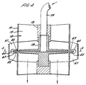
- FIG. 4 and 5 a modified form of the excavation apparatus of Figures 1 and 2 is shown and like parts have been allotted the same reference numerals.
- the main difference is that the fixed vanes 31 on the inner side of tube 10 around the periphery of the propeller are omitted.
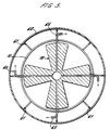
- the tube is formed with a narrow annular slit 60 encircling the outer periphery of the propeller and vertically extending fixed vanes 61 are secured to the outer side of the tube extending across the slit at spaced locations around the tube as best seen in Figure 5.
- An annular sleeve 62 encircles and is secured to the outer peripheries of the vanes 61 to strengthen the structure.
- Deep slots 63 extend into the vanes 61 from the slit in the tube, the bottoms of the slots being rounded as indicated at 64.
- the propeller blades are formed with extended jet tubes 65 projecting from the outer peripheries of the blades to extend through the slit 60 in the tube and in alignment with the slots in the vanes.
- the jet tubes are turned to face tangentially of the propeller to direct the water jets therefrom onto the vanes 62 and the static body of water lying between the vanes to cause the propeller to rotate and draw water through the tube as before. In this case however the jets do not act in the turbulent water flow passing through the tube under the action of the propeller as in the arrangements of Figures 1 to 3.
- a further benefit is gained for a given diameter of tube and propeller by the increase in the radius at which the jets act from the axis of the propeller, thereby increasing the torque generated on the propeller by the jets for a given water pressure.
- FIG. 6 of the drawings there is shown an application of the excavation apparatus of Figures 4 and 5 to a drill string.
- the drill cuttings are dumped on the seabed and very often cover up the drill template and other structures.
- the present method of removing these cuttings (which may be up to 5 metres deep) is to use high pressure water pumped down the drill string through a "jet sub" tool.
- the tool is generally not very successful in clearing large areas and operators are very cautious in using them since the high pressure (high water velocity) can damage seafloor equipment.
- a very much better system is to wash the area with a very large flow of low velocity (non-destructive) water. This can be achieved by fitting the underwater excavation apparatus as described earlier directly to the drill string and using the high pressure of water supply to power it as will now be described in detail with reference to Figure 6.
- a drilling rig is indicated generally at 50 from which a drill string 51 depends.
- a high pressure water pump 52 is mounted on the deck of the drilling rig which draws water into an inlet conduit 53 from the sea and discharges water at high pressure through a central conduit 54 of the drill string.
- the underwater excavation apparatus is mounted at the lower end 55 of the drill string and like parts have been given the same reference numerals.
- the outer sleeve 56 of the lower end of the drill string has an externally threaded portion 57 to engage in a screw threaded socket in the collar 13 at the upper end of the tube 10 to secure the excavator to the lower end of the sleeve of the drill string.
- the high pressure rotary coupling 26 of the excavator is housed in the lower end of the sleeve 13 instead of above the sleeve as in the previously described embodiment and the inner conduit 54 of the drill string is connected to the upper side of the coupling.
- the lower side of the coupling is connected by a conduit 17 to the propeller as before. The supply of high pressure water is thus communicated from the drill string to the blades of the jet prop.
- the high pressure water jet delivered through the drill string exists from the jets at the outer periphery of the propeller to impinge on the vanes and static water between the vanes to cause the propeller to rotate drawing water downwardly through the conduit and delivering the water at the lower end of the conduit to act on the seabed as illustrated by the heavy arrows.
- an object to be exposed or examined on the seabed prior to excavation can be exposed by the jet of water acting on the seabed to create a shallow trench on the seabed as illustrated.
Landscapes
- Engineering & Computer Science (AREA)
- Mechanical Engineering (AREA)
- Mining & Mineral Resources (AREA)
- Civil Engineering (AREA)
- General Engineering & Computer Science (AREA)
- Structural Engineering (AREA)
- Life Sciences & Earth Sciences (AREA)
- Chemical & Material Sciences (AREA)
- Analytical Chemistry (AREA)
- Soil Sciences (AREA)
- General Life Sciences & Earth Sciences (AREA)
- Paleontology (AREA)
- Earth Drilling (AREA)
Claims (12)
- Unterwasser-Ausschachtvorrichtung, die einen hohlen Körper (10) aufweist, der einen Einlaß (11) zur Aufnahme von Wasser, einen Auslaß (12) zur Abgabe von Wasser und einen motorgetriebenen Propeller (18) mit einer Vielzahl von Flügeln (20) hat, die an einer Stelle in dem hohlen Körper drehbar angebracht sind, um Wasser durch den Einlaß anzusaugen und einen Wasserstrom durch den Auslaß zu fördern; dadurch gekennzeichnet, daß an den Propellerflügeln Düseneinrichtungen (65) vorgesehen sind und Einrichtungen (25) vorgesehen sind, um den Düseneinrichtungen Wasser unter Druck zuzuführen, um zu bewirken, daß der Propeller sich dreht und dadurch einen Wasserstrom durch den Auslaß fördert, um Material auf dem Meeresboden zu verdrängen; und daß der hohle Körper einen um ihn verlaufenden Schlitz (60) an dem Ört des Propellers hat, eine Ringwand (62) an der Außenseite des Hohlkörpers angebracht ist, die sich an beiden Seiten des Schlitzes erstreckt und um den hohlen Körper herum eine Ringkammer definiert, und daß die Düseneinrichtungen an Vorderenden (22) der Propellerflügel angeordnet sind und durch den ringförmigen Schlitz in die Ringkammer ragen und in bezug auf die Flügel tangential gerichtet sind und Wasserstrahlen erzeugen, die gegen das in der Ringkammer enthaltene Wasser wirken und so den Propeller veranlassen, sich innerhalb des hohlen Körpers zu drehen.
- Unterwasser-Ausschachtvorrichtung nach Anspruch 1, dadurch gekennzeichnet, daß Mittel (29) vorgesehen sind, um Wasser unter Druck von der Mitte des Propellers zu den Düseneinrichtungen zu transportieren.
- Unterwasser-Ausschachtvorrichtung nach Anspruch 2, dadurch gekennzeichnet, daß die Flügel des Propellers hohl sind, um Kanäle (29) zu bilden, die sich von der Mitte des Propellers zu den Flügelvorderenden (22) erstrecken, und daß die Düseneinrichtungen (65) an den Flügelvorderenden mit den Kanälen in Kommunikation sind.
- Unterwasser-Ausschachtvorrichtung nach einem der Ansprüche 1 bis 3, dadurch gekennzeichnet, daß Schaufeln (61) an beabstandeten Stellen um den Außenumfang des Körpers (10) herum zwischen dem körper und der Ringwand (62) angeordnet sind und sich zu beiden Seiten des Schlitzes (60) in dem hohlen Körper erstrecken, wobei die Schaufeln Schlitze (63) haben, die von dem Schlitz in dem hohlen Körper in die Schaufeln verlaufen, und die Düsen an den Flügeln des Propellers sich davon nach außen in Ausfluchtung mit den Schlitzen in den äußeren Schaufeln erstrecken, wobei die Düsen so abgewinkelt sind, daß sie in bezug auf den Propeller tangential gerichtet sind und so auf die Schaufeln treffen, daß sie eine Gegenkraft auf die Schaufeln erzeugen, die wirksam ist, um jeder Tendenz des hohlen Körpers, sich in derselben Richtung wie der Propeller zu drehen, entgegenzuwirken.
- Unterwasser-Ausschachtvorrichtung nach Anspruch 4, dadurch gekennzeichnet, daß die Schaufeln (61) an dem hohlen Körper an beiden Seiten des ringförmigen Schlitzes angebracht sind und die Ringwand an den Außenumfängen der Schaufeln angebracht ist.
- Unterwasser-Ausschachtvorrichtung nach einem der vorhergehenden Ansprüche, dadurch gekennzeichnet, daß der Propeller (18) auf einer Welle (17) montiert ist, die in dem hohlen Körper angeordneten beabstandeten Lagergehäusen (13, 14) angebracht ist, wobei die Welle hohl ist, um einen Kanal für eine Zufuhr von Hochdruckwasser zu den Düsen an den Propellerflügeln zu bilden.
- Unterwasser-Ausschachtvorrichtung nach Anspruch 6, dadurch gekennzeichnet, daß die Lagergehäuse (13, 14) an sich radial erstreckenden festgelegten Flügeln (15, 16) angebracht sind, die sich zu der Wand des hohlen Körpers aufstromseitig und/oder abstromseitig von dem Propeller erstrecken, wobei die Flügel in Ebenen liegen, die längs des hohlen Körpers verlaufen, um eine Strömung in Längsrichtung längs des hohlen Körpers zu leiten und Wirbel zu verringern, die aus dem Betrieb des Propellers resultieren.
- Unterwasser-Ausschachtvorrichtung nach einem der vorhergehenden Ansprüche, dadurch gekennzeichnet, daß der Einlaß (11) zu dem hohlen Körper in dieselbe Richtung wie der Auslaß (12) weist, so daß der Rückwirkung in dem Körper beim Ausstoßen von Wasser aus dem Auslaß von der Rückwirkung beim Ansaugen von Wasser entgegengewirkt wird.
- Unterwasser-Ausschachtvorrichtung nach Anspruch 8, dadurch gekennzeichnet, daß der Einlaß (11) den hohlen Körper angrenzend an ein Ende davon umschließt und daß Einrichtungen (38, 39) vorgesehen sind, um die Strömungsrichtung zwischen dem Einlaß und dem hohlen Körper umzukehren, so daß die Strömungsrichtung in den Einlaß entgegengesetzt zu der Strömungsrichtung aus dem Auslaß ist.
- Unterwasser-Ausschachtvorrichtung nach einem der vorhergehenden Ansprüche, dadurch gekennzeichnet, daß eine Auftriebseinrichtung (36) vorgesehen ist, um die Vorrichtung unter Wasser schwimmfähig zu machen, und Verankerungsmittel vorgesehen sind, um den hohlen Körper mit dem Auslaß nach unten weisend zu halten, um auf den Meeresboden einzuwirken.
- Unterwasser-Ausschachtvorrichtung nach einem der vorhergehenden Ansprüche in Kombination mit einem Bohrstrang (51), wobei der hohle Körper (10) der Vorrichtung an dem unteren Ende des Bohrstrangs angebracht ist, um Material auf dem Meeresboden unterhalb des Bohrstrangs zu verdrängen.
- Unterwasser-Ausschachtvorrichtung nach Anspruch 11, dadurch gekennzeichnet, daß der Bohrstrang eine Hochdruck-Wasserversorgung (52, 53) aufweist, die axial durch die Mitte des Bohrstrangs nach unten verläuft und mit den Wasserdüseneinrichtungen an dem Propeller der Ausschachtvorrichtung verbunden ist, um diesen Propeller zu drehen, und dadurch die Wasserströmung durch den hohlen Körper der Ausschachtvorrichtung erzeugt, die auf den Meeresboden unterhalb des Bohrstrangs gerichtet ist.
Applications Claiming Priority (2)
| Application Number | Priority Date | Filing Date | Title |
|---|---|---|---|
| GB909002532A GB9002532D0 (en) | 1990-02-05 | 1990-02-05 | Improvements in or relating to underwater excavation apparatus |
| PCT/GB1991/000611 WO1992018701A1 (en) | 1990-02-05 | 1991-04-18 | Improvements in or relating to underwater excavation apparatus |
Publications (2)
| Publication Number | Publication Date |
|---|---|
| EP0580573A1 EP0580573A1 (de) | 1994-02-02 |
| EP0580573B1 true EP0580573B1 (de) | 1997-05-02 |
Family
ID=10670448
Family Applications (1)
| Application Number | Title | Priority Date | Filing Date |
|---|---|---|---|
| EP91908095A Expired - Lifetime EP0580573B1 (de) | 1990-02-05 | 1991-04-18 | Verbesserte vorrichtung für unterwasserausgrabung |
Country Status (10)
| Country | Link |
|---|---|
| US (2) | US5480291A (de) |
| EP (1) | EP0580573B1 (de) |
| JP (1) | JPH06506030A (de) |
| AU (1) | AU657092B2 (de) |
| CA (1) | CA2108013C (de) |
| DE (1) | DE69125952T2 (de) |
| DK (1) | DK0580573T3 (de) |
| GB (2) | GB9002532D0 (de) |
| NO (1) | NO300930B1 (de) |
| WO (1) | WO1992018701A1 (de) |
Families Citing this family (23)
| Publication number | Priority date | Publication date | Assignee | Title |
|---|---|---|---|---|
| GB9002532D0 (en) * | 1990-02-05 | 1990-04-04 | Consortium Resource Management | Improvements in or relating to underwater excavation apparatus |
| GB2297777A (en) * | 1995-02-07 | 1996-08-14 | Hollandsche Betongroep Nv | Underwater excavation apparatus |
| NL9500228A (nl) * | 1995-02-07 | 1996-09-02 | Hollandsche Betongroep Nv | Inrichting voor het opwekken van een plaatselijke waterstroming. |
| GB2301128B (en) * | 1995-05-24 | 1999-03-17 | Hector Filippus Alexand Susman | Improvements in or relating to underwater excavation apparatus |
| GB9512602D0 (en) | 1995-06-21 | 1995-08-23 | Susman Hector F A | Improvements in or relating to underwater excavation apparatus |
| GB2289912B (en) * | 1995-07-13 | 1996-05-15 | Nicholas Victor Sills | Underwater excavation and marine vehicle propulsion apparatus |
| GB2304353B (en) * | 1995-08-16 | 1999-01-06 | George John Stroud | Underwater excavation apparatus |
| JPH09177057A (ja) * | 1995-12-27 | 1997-07-08 | Furoo Techno Kk | 水中堆積物の処理方法とその装置 |
| GB2315787B (en) * | 1996-03-01 | 1999-07-21 | Seabed Impeller Levelling And | Dredging apparatus |
| GB0104642D0 (en) * | 2001-02-26 | 2001-04-11 | Wilkinson Michael J | The movement of silt sludge or other materials utilising a Venturi or vertex effect |
| NL1020754C2 (nl) * | 2002-06-04 | 2003-12-08 | Seatools B V | Inrichting voor het verwijderen van sediment en functie-eenheid voor toepassing daarin. |
| GB0301660D0 (en) * | 2003-01-24 | 2003-02-26 | Redding John | Dredging scouring & excavation |
| GB2444259B (en) | 2006-11-29 | 2011-03-02 | Rotech Holdings Ltd | Improvements in and relating to underwater excavation apparatus |
| US20100139130A1 (en) * | 2008-12-08 | 2010-06-10 | Wagenaar Dirk C | Underwater Excavation Tool |
| KR100909876B1 (ko) | 2009-01-30 | 2009-07-30 | 주식회사 경동건설 | 공압과 수압을 이용한 수직갱 굴착장치 및 굴착방법 |
| CN103857879B (zh) * | 2011-10-04 | 2016-08-24 | 磪焃善 | 轴流式涡轮机 |
| JP6103831B2 (ja) * | 2012-06-22 | 2017-03-29 | 中外テクノス株式会社 | 流体圧モーターにおける高速回転装置及びその高速回転方法 |
| GB2538974B (en) * | 2015-06-01 | 2019-03-13 | Jbs Group Scotland Ltd | Underwater excavation apparatus |
| GB201614460D0 (en) * | 2016-08-24 | 2016-10-05 | Rotech Group Ltd | Improvements in and relating to underwater excavation apparatus |
| CN209638120U (zh) * | 2017-10-20 | 2019-11-15 | 创科(澳门离岸商业服务)有限公司 | 风扇 |
| EP4303401A4 (de) * | 2021-03-04 | 2025-03-19 | Toa Corporation | Verfahren zur extraktion von unterwasserressourcen |
| JP7576269B2 (ja) * | 2021-03-04 | 2024-10-31 | 東亜建設工業株式会社 | 水底資源の採取システムおよび採取方法 |
| US12012836B2 (en) * | 2021-03-04 | 2024-06-18 | Toa Corporation | Water bottom resource collecting system and collecting method |
Family Cites Families (18)
| Publication number | Priority date | Publication date | Assignee | Title |
|---|---|---|---|---|
| US290039A (en) * | 1883-12-11 | Hydraulic motor | ||
| US69294A (en) * | 1867-09-24 | Improvement in watee-wheels | ||
| US191668A (en) * | 1877-06-05 | Improvement in water-wheels | ||
| US2225412A (en) * | 1936-11-05 | 1940-12-17 | George W Ferling | Locomotive draft inducer |
| US2705051A (en) * | 1949-09-13 | 1955-03-29 | Hauser Arnold | Fluid driven propeller |
| US2920813A (en) * | 1958-01-02 | 1960-01-12 | Westinghouse Electric Corp | Gas reaction rotors |
| US3286984A (en) * | 1965-12-27 | 1966-11-22 | Bachl Herbert | Rotary turbine |
| US3398694A (en) * | 1966-08-11 | 1968-08-27 | Marine Constr & Design Co | Submersible pump device for net brailing |
| FR1575616A (de) * | 1968-02-29 | 1969-07-25 | ||
| US3910728A (en) * | 1973-11-15 | 1975-10-07 | Albert H Sloan | Dewatering pump apparatus |
| US3926534A (en) * | 1974-01-02 | 1975-12-16 | Kobe Inc | Turbine |
| US4138202A (en) * | 1976-12-03 | 1979-02-06 | Eller J Marlin | Hydraulic motor system for driving a submersible impeller pump in which reversal of hydraulic flow is prevented |
| GB2033060B (en) * | 1978-10-31 | 1982-12-22 | Eller L | Pumping apparatus |
| US4452566A (en) * | 1981-06-15 | 1984-06-05 | Institute Of Gas Technology | Reactive impeller for pressurizing hot flue gases |
| US4756671A (en) * | 1983-02-28 | 1988-07-12 | Marco Seattle, Inc. | Low damage hydraulic fish pumping system |
| GB8603189D0 (en) * | 1986-02-10 | 1986-03-19 | Consortium Recovery Ltd | Remote underwater excavator & sampler |
| GB9002532D0 (en) * | 1990-02-05 | 1990-04-04 | Consortium Resource Management | Improvements in or relating to underwater excavation apparatus |
| US5263814A (en) * | 1992-05-21 | 1993-11-23 | Jang Young Wan | Water driven turbine |
-
1990
- 1990-02-05 GB GB909002532A patent/GB9002532D0/en active Pending
-
1991
- 1991-02-05 GB GB9102471A patent/GB2240568B/en not_active Expired - Fee Related
- 1991-04-18 JP JP3507524A patent/JPH06506030A/ja active Pending
- 1991-04-18 DK DK91908095.2T patent/DK0580573T3/da active
- 1991-04-18 US US08/133,095 patent/US5480291A/en not_active Expired - Fee Related
- 1991-04-18 WO PCT/GB1991/000611 patent/WO1992018701A1/en not_active Ceased
- 1991-04-18 AU AU76726/91A patent/AU657092B2/en not_active Ceased
- 1991-04-18 EP EP91908095A patent/EP0580573B1/de not_active Expired - Lifetime
- 1991-04-18 DE DE69125952T patent/DE69125952T2/de not_active Expired - Fee Related
- 1991-04-18 CA CA002108013A patent/CA2108013C/en not_active Expired - Fee Related
-
1993
- 1993-10-15 NO NO933721A patent/NO300930B1/no not_active IP Right Cessation
-
1995
- 1995-12-07 US US08/568,526 patent/US5607289A/en not_active Expired - Fee Related
Also Published As
| Publication number | Publication date |
|---|---|
| DE69125952D1 (de) | 1997-06-05 |
| GB9002532D0 (en) | 1990-04-04 |
| EP0580573A1 (de) | 1994-02-02 |
| NO933721L (no) | 1993-11-30 |
| US5607289A (en) | 1997-03-04 |
| CA2108013C (en) | 2001-08-21 |
| GB9102471D0 (en) | 1991-03-20 |
| GB2240568A (en) | 1991-08-07 |
| DE69125952T2 (de) | 1997-12-18 |
| JPH06506030A (ja) | 1994-07-07 |
| NO933721D0 (no) | 1993-10-15 |
| AU7672691A (en) | 1992-11-17 |
| CA2108013A1 (en) | 1992-10-19 |
| US5480291A (en) | 1996-01-02 |
| WO1992018701A1 (en) | 1992-10-29 |
| NO300930B1 (no) | 1997-08-18 |
| GB2240568B (en) | 1993-10-27 |
| DK0580573T3 (da) | 1997-08-04 |
| AU657092B2 (en) | 1995-03-02 |
Similar Documents
| Publication | Publication Date | Title |
|---|---|---|
| US5480291A (en) | Underwater excavation apparatus | |
| US4936031A (en) | Apparatus for excavating soil and the like using supersonic jets | |
| US4436168A (en) | Thrust generator for boring tools | |
| EP4036322B1 (de) | Verbesserungen an oder im zusammenhang mit einer unterwasseraushubvorrichtung | |
| EP3781750B1 (de) | Verbesserungen an oder im zusammenhang mit einer unterwasseraushubvorrichtung | |
| AU592425B2 (en) | Arrangement for underwater drilling of foundations | |
| US3909960A (en) | Loose material recovery system having a mixing box | |
| US5327980A (en) | Drill head | |
| TW202336320A (zh) | 水下挖掘設備之改良及與水下挖掘設備相關之改良 | |
| KR20140043425A (ko) | 고압펌프와 인력발생장치(引力發生裝置)와 와류발생장치(渦流發生裝置), 공기압축기 등을 이용한 준설장치와 준설토이송장치 및 그 방법 | |
| JPH029991A (ja) | タービン駆動式回転ポンプ | |
| CN222408505U (zh) | 掘进式锚固钻头、锚定组件以及水下潜航器 | |
| US5316449A (en) | Motor-driven pump with reaction turbine | |
| EA009894B1 (ru) | Газосепаратор | |
| GB2304353A (en) | Underwater excavation apparatus | |
| GB2289912A (en) | Underwater excavation or marine vehicle propulsion apparatus | |
| JPS6363750B2 (de) | ||
| GB2359103A (en) | Balanced thrust underwater excavation apparatus | |
| WO2025003676A1 (en) | Device, apparatus, system and method for sediment plume suppression | |
| JP2529669B2 (ja) | 掘削装置 | |
| JPS6193275A (ja) | 水中作業装置の駆動方法 | |
| GB2318154A (en) | Turbine-driven fluid impelling apparatus |
Legal Events
| Date | Code | Title | Description |
|---|---|---|---|
| PUAI | Public reference made under article 153(3) epc to a published international application that has entered the european phase |
Free format text: ORIGINAL CODE: 0009012 |
|
| 17P | Request for examination filed |
Effective date: 19930930 |
|
| AK | Designated contracting states |
Kind code of ref document: A1 Designated state(s): BE DE DK ES FR GR IT NL SE |
|
| 17Q | First examination report despatched |
Effective date: 19950217 |
|
| GRAG | Despatch of communication of intention to grant |
Free format text: ORIGINAL CODE: EPIDOS AGRA |
|
| GRAH | Despatch of communication of intention to grant a patent |
Free format text: ORIGINAL CODE: EPIDOS IGRA |
|
| RAP3 | Party data changed (applicant data changed or rights of an application transferred) |
Owner name: UNDERWATER EXCAVATION LIMITED |
|
| GRAH | Despatch of communication of intention to grant a patent |
Free format text: ORIGINAL CODE: EPIDOS IGRA |
|
| GRAA | (expected) grant |
Free format text: ORIGINAL CODE: 0009210 |
|
| AK | Designated contracting states |
Kind code of ref document: B1 Designated state(s): BE DE DK ES FR GR IT NL SE |
|
| PG25 | Lapsed in a contracting state [announced via postgrant information from national office to epo] |
Ref country code: GR Free format text: LAPSE BECAUSE OF FAILURE TO SUBMIT A TRANSLATION OF THE DESCRIPTION OR TO PAY THE FEE WITHIN THE PRESCRIBED TIME-LIMIT Effective date: 19970502 Ref country code: ES Free format text: THE PATENT HAS BEEN ANNULLED BY A DECISION OF A NATIONAL AUTHORITY Effective date: 19970502 |
|
| REF | Corresponds to: |
Ref document number: 69125952 Country of ref document: DE Date of ref document: 19970605 |
|
| ET | Fr: translation filed | ||
| PG25 | Lapsed in a contracting state [announced via postgrant information from national office to epo] |
Ref country code: SE Effective date: 19970802 |
|
| REG | Reference to a national code |
Ref country code: DK Ref legal event code: T3 |
|
| PLBE | No opposition filed within time limit |
Free format text: ORIGINAL CODE: 0009261 |
|
| STAA | Information on the status of an ep patent application or granted ep patent |
Free format text: STATUS: NO OPPOSITION FILED WITHIN TIME LIMIT |
|
| 26N | No opposition filed | ||
| PGFP | Annual fee paid to national office [announced via postgrant information from national office to epo] |
Ref country code: DK Payment date: 20010208 Year of fee payment: 11 |
|
| PGFP | Annual fee paid to national office [announced via postgrant information from national office to epo] |
Ref country code: BE Payment date: 20010213 Year of fee payment: 11 |
|
| PGFP | Annual fee paid to national office [announced via postgrant information from national office to epo] |
Ref country code: FR Payment date: 20010427 Year of fee payment: 11 |
|
| PGFP | Annual fee paid to national office [announced via postgrant information from national office to epo] |
Ref country code: DE Payment date: 20010626 Year of fee payment: 11 |
|
| PG25 | Lapsed in a contracting state [announced via postgrant information from national office to epo] |
Ref country code: DK Free format text: LAPSE BECAUSE OF NON-PAYMENT OF DUE FEES Effective date: 20020430 Ref country code: BE Free format text: LAPSE BECAUSE OF NON-PAYMENT OF DUE FEES Effective date: 20020430 |
|
| PG25 | Lapsed in a contracting state [announced via postgrant information from national office to epo] |
Ref country code: DE Free format text: LAPSE BECAUSE OF NON-PAYMENT OF DUE FEES Effective date: 20021101 |
|
| REG | Reference to a national code |
Ref country code: DK Ref legal event code: EBP |
|
| PG25 | Lapsed in a contracting state [announced via postgrant information from national office to epo] |
Ref country code: FR Free format text: LAPSE BECAUSE OF NON-PAYMENT OF DUE FEES Effective date: 20021231 |
|
| REG | Reference to a national code |
Ref country code: FR Ref legal event code: ST |
|
| PG25 | Lapsed in a contracting state [announced via postgrant information from national office to epo] |
Ref country code: IT Free format text: LAPSE BECAUSE OF NON-PAYMENT OF DUE FEES;WARNING: LAPSES OF ITALIAN PATENTS WITH EFFECTIVE DATE BEFORE 2007 MAY HAVE OCCURRED AT ANY TIME BEFORE 2007. THE CORRECT EFFECTIVE DATE MAY BE DIFFERENT FROM THE ONE RECORDED. Effective date: 20050418 |
|
| NLS | Nl: assignments of ep-patents |
Owner name: PSL ENERGY SERVICES LIMITED Effective date: 20070531 |
|
| PGFP | Annual fee paid to national office [announced via postgrant information from national office to epo] |
Ref country code: NL Payment date: 20100412 Year of fee payment: 20 |
|
| REG | Reference to a national code |
Ref country code: NL Ref legal event code: V4 Effective date: 20110418 |
|
| PG25 | Lapsed in a contracting state [announced via postgrant information from national office to epo] |
Ref country code: NL Free format text: LAPSE BECAUSE OF EXPIRATION OF PROTECTION Effective date: 20110418 |