EP0580908A1 - Flüssigkristallanzeige mit einer Rücklichtvorrichtung nicht dicker als 7mm - Google Patents
Flüssigkristallanzeige mit einer Rücklichtvorrichtung nicht dicker als 7mm Download PDFInfo
- Publication number
- EP0580908A1 EP0580908A1 EP92307861A EP92307861A EP0580908A1 EP 0580908 A1 EP0580908 A1 EP 0580908A1 EP 92307861 A EP92307861 A EP 92307861A EP 92307861 A EP92307861 A EP 92307861A EP 0580908 A1 EP0580908 A1 EP 0580908A1
- Authority
- EP
- European Patent Office
- Prior art keywords
- liquid crystal
- crystal display
- plate
- light guide
- guide plate
- Prior art date
- Legal status (The legal status is an assumption and is not a legal conclusion. Google has not performed a legal analysis and makes no representation as to the accuracy of the status listed.)
- Withdrawn
Links
- 239000004973 liquid crystal related substance Substances 0.000 title claims abstract description 135
- 229910052751 metal Inorganic materials 0.000 claims abstract description 31
- 239000002184 metal Substances 0.000 claims abstract description 31
- 238000009792 diffusion process Methods 0.000 claims abstract description 17
- 229910052782 aluminium Inorganic materials 0.000 claims abstract description 11
- XAGFODPZIPBFFR-UHFFFAOYSA-N aluminium Chemical compound [Al] XAGFODPZIPBFFR-UHFFFAOYSA-N 0.000 claims abstract description 11
- 239000011248 coating agent Substances 0.000 claims abstract description 8
- 238000000576 coating method Methods 0.000 claims abstract description 8
- 230000000717 retained effect Effects 0.000 claims description 9
- 230000002093 peripheral effect Effects 0.000 claims description 7
- 229910000838 Al alloy Inorganic materials 0.000 claims description 4
- 239000004411 aluminium Substances 0.000 claims description 3
- 238000000465 moulding Methods 0.000 claims description 3
- 230000003287 optical effect Effects 0.000 abstract description 18
- 230000006735 deficit Effects 0.000 abstract description 8
- NIXOWILDQLNWCW-UHFFFAOYSA-N acrylic acid group Chemical group C(C=C)(=O)O NIXOWILDQLNWCW-UHFFFAOYSA-N 0.000 abstract description 4
- 230000001771 impaired effect Effects 0.000 description 6
- 239000010410 layer Substances 0.000 description 5
- 239000004033 plastic Substances 0.000 description 4
- 229920003023 plastic Polymers 0.000 description 4
- 230000035939 shock Effects 0.000 description 4
- 239000011247 coating layer Substances 0.000 description 3
- 238000000034 method Methods 0.000 description 3
- 229920000139 polyethylene terephthalate Polymers 0.000 description 3
- 239000005020 polyethylene terephthalate Substances 0.000 description 3
- 230000005855 radiation Effects 0.000 description 2
- 230000009467 reduction Effects 0.000 description 2
- 230000008859 change Effects 0.000 description 1
- 230000000694 effects Effects 0.000 description 1
- 239000000463 material Substances 0.000 description 1
- 230000004048 modification Effects 0.000 description 1
- 238000012986 modification Methods 0.000 description 1
- 244000144985 peep Species 0.000 description 1
- -1 polyethylene terephthalate Polymers 0.000 description 1
- 230000008569 process Effects 0.000 description 1
- 230000001902 propagating effect Effects 0.000 description 1
- 238000002834 transmittance Methods 0.000 description 1
Images


Classifications
-
- G—PHYSICS
- G02—OPTICS
- G02F—OPTICAL DEVICES OR ARRANGEMENTS FOR THE CONTROL OF LIGHT BY MODIFICATION OF THE OPTICAL PROPERTIES OF THE MEDIA OF THE ELEMENTS INVOLVED THEREIN; NON-LINEAR OPTICS; FREQUENCY-CHANGING OF LIGHT; OPTICAL LOGIC ELEMENTS; OPTICAL ANALOGUE/DIGITAL CONVERTERS
- G02F1/00—Devices or arrangements for the control of the intensity, colour, phase, polarisation or direction of light arriving from an independent light source, e.g. switching, gating or modulating; Non-linear optics
- G02F1/01—Devices or arrangements for the control of the intensity, colour, phase, polarisation or direction of light arriving from an independent light source, e.g. switching, gating or modulating; Non-linear optics for the control of the intensity, phase, polarisation or colour
- G02F1/13—Devices or arrangements for the control of the intensity, colour, phase, polarisation or direction of light arriving from an independent light source, e.g. switching, gating or modulating; Non-linear optics for the control of the intensity, phase, polarisation or colour based on liquid crystals, e.g. single liquid crystal display cells
- G02F1/133—Constructional arrangements; Operation of liquid crystal cells; Circuit arrangements
- G02F1/1333—Constructional arrangements; Manufacturing methods
- G02F1/1335—Structural association of cells with optical devices, e.g. polarisers or reflectors
- G02F1/1336—Illuminating devices
- G02F1/133615—Edge-illuminating devices, i.e. illuminating from the side
-
- G—PHYSICS
- G02—OPTICS
- G02F—OPTICAL DEVICES OR ARRANGEMENTS FOR THE CONTROL OF LIGHT BY MODIFICATION OF THE OPTICAL PROPERTIES OF THE MEDIA OF THE ELEMENTS INVOLVED THEREIN; NON-LINEAR OPTICS; FREQUENCY-CHANGING OF LIGHT; OPTICAL LOGIC ELEMENTS; OPTICAL ANALOGUE/DIGITAL CONVERTERS
- G02F1/00—Devices or arrangements for the control of the intensity, colour, phase, polarisation or direction of light arriving from an independent light source, e.g. switching, gating or modulating; Non-linear optics
- G02F1/01—Devices or arrangements for the control of the intensity, colour, phase, polarisation or direction of light arriving from an independent light source, e.g. switching, gating or modulating; Non-linear optics for the control of the intensity, phase, polarisation or colour
- G02F1/13—Devices or arrangements for the control of the intensity, colour, phase, polarisation or direction of light arriving from an independent light source, e.g. switching, gating or modulating; Non-linear optics for the control of the intensity, phase, polarisation or colour based on liquid crystals, e.g. single liquid crystal display cells
- G02F1/133—Constructional arrangements; Operation of liquid crystal cells; Circuit arrangements
- G02F1/1333—Constructional arrangements; Manufacturing methods
- G02F1/133308—Support structures for LCD panels, e.g. frames or bezels
Definitions
- the present invention relates to a liquid crystal display device with a back light to be used as a display device in a word processor, a personal computer, or the like.
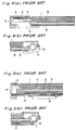
- the liquid crystal display devices have a panel shape, their configuration being such that a liquid crystal display panel 1 is fitted into a metal angle 4, as shown in Fig. 3.
- Fig. 4 (a) and Fig. 5 (a) are sectional views taken along the line A - A in Fig. 3, and
- Fig. 4 (b) and Fig. 5 (b) are sectional views taken along the line B - B in Fig. 3.
- the liquid crystal display device as shown in Figs. 4 (a) and (b) includes: a liquid crystal display panel 1 having liquid crystal drivers 2 and 3 on its periphery; a light guide plate 6 with a thickness of 2 mm and a light transmittance having a diffusion sheet 5 disposed on its surface and a light source 12 disposed in the vicinity of its one end face; and a reflecting plate 8 for, when a beam of light emitted from the light source 12 and propagating within the light guide plate 6 leaks out through the face thereof other than the liquid crystal display panel 1 side face, reflecting the light toward the liquid crystal display panel 1, wherein the liquid crystal display panel 1, the light guide plate 6, and the reflecting plate 8 are retained by a plastic retainer member 9 and the metal angle 4.
- the liquid crystal display device as shown in Figs. 5 (a) and (b) include the same light source 12, diffusion sheet 5, and light guide plate 6 as in the liquid crystal display device shown in Figs. 4 (a) and (b).
- a reflecting plate 7 is made of a metal plate with a white reflecting coating, and below the reflecting plate 7 are disposed liquid crystal drivers 2 and 3.
- the liquid crystal drivers 2 and 3 are electrically connected to the liquid crystal display panel 1 via a rubber connector 10.
- the conventional liquid crystal display devices as described above are, in each case, disadvantageous in that the devices cannot be thinned or reduced in weight as much as demanded to such devices on some structural accounts.
- Mechanical characteristic requirements for liquid crystal display devices are a vibration resistance of 1 G and a shock resistance 50 G at 500 Hz. Further, optical characteristic requirements are a contrast of 12 : 1 and a brightness of 30 nit.
- the liquid crystal display device as shown in Figs. 4 (a) and (b) is 7 mm in thickness and that in Figs. 5 (a) and (b) is 10 mm, both meeting the above-mentioned mechanical and optical characteristic requirements.
- the members of the light guide plate 6, the reflecting plates 7 and 8, the retainer member 9, and the like were simply reduced in thickness so as to attain a thickness of the liquid crystal display device as thin as not more than 5 mm, those mechanical and optical characteristic requirements could no longer be met.
- the object of the present invention is therefore to provide a liquid crystal display device which is as thin as not more than 7 mm and yet free from any impairment in either mechanical or optical characteristics.
- a liquid crystal display device having: a liquid crystal display section in which a liquid crystal driver is disposed on a peripheral portion of a liquid crystal display panel; and a back light section in which a light source is disposed in the vicinity of at least one end face of a light guide plate disposed below the liquid crystal display section, wherein the liquid crystal display section and the back light section are sandwiched and securely retained by a pair of metal plates.
- the liquid crystal display section having the liquid crystal driver disposed on the periphery of the liquid crystal display panel, and the back light section having a light source disposed in the vicinity of at least one end face of the light guide plate disposed below the liquid crystal display section are sandwiched and securely retained by the pair of metal plates.
- the thin type liquid crystal display device can be provided without reducing the thickness of the liquid crystal display section and the back light section to a considerable extent.
- the resulting liquid crystal display device is, even if a thin type, free from any impairment of either mechanical or optical characteristics.
- one of the pair of metal plates sandwiching the liquid crystal display section and the back light section is a reflecting plate disposed below the light guide plate so as to reflect light derived from the light guide plate toward the liquid crystal display section.
- the liquid crystal display device can be provided in a thin type without being impaired in its mechanical and optical characteristics, by virtue of its arrangement that one sheet of metal plate serves two functions.
- the reflectance of the reflecting plate is not less than 70%.
- the 70% or more reflectance of the reflecting plate enables the liquid crystal display device to be maintained at a brightness over the specified level.
- a white reflecting layer is formed in the reflecting surface of the reflecting plate.
- the white reflecting layer is formed of a coating layer.
- the metal plate constituting the reflecting plate is formed of aluminium or an aluminum alloy.
- the liquid crystal display device can be reduced in weight.
- the reflecting plate covers over every end face of the light guide plate other than one end face of the light guide plate of the light source side.
- the reflecting plate is formed by integral molding so as to cover the entire lower face of the light guide plate, an end face of the light guide plate on the side other than the light source side, and part of the light source; the light guide plate, a diffusion plate, and the liquid crystal display panel having the liquid crystal driver disposed on its peripheral portion are stacked on the reflecting plate one over another; and wherein the stacked reflecting plate, light guide plate, diffusion plate, and liquid crystal display panel are sandwiched and securely retained by a metal angle provided with a display window.
- the liquid crystal display device is, even if a thin type, free from any impairment in either mechanical or optical characteristics.
- Fig. 1 presents sectional views of a liquid crystal display device of an embodiment according to the present invention.
- the liquid crystal display device in this embodiment has an appearance as shown in Fig. 3.
- Fig. 1 (a) is a sectional view taken along the line A - A in Fig. 3 as directed by arrows and
- Fig. 1 (b) is another taken along the line B - B in Fig. 3 as directed by arrows.
- the liquid crystal display device of the present embodiment primarily comprises: a liquid crystal display section composed of a liquid crystal display panel 21, a printed board 22, an LSI (large scale integrated circuit) 23, and the like; and a back light section composed of a diffusion plate 25, a light guide plate 26, a reflecting plate 27, a light source 29, and the like.
- a liquid crystal display section composed of a liquid crystal display panel 21, a printed board 22, an LSI (large scale integrated circuit) 23, and the like
- a back light section composed of a diffusion plate 25, a light guide plate 26, a reflecting plate 27, a light source 29, and the like.
- liquid crystal driver made up of a printed board 22 and an LSI 23 for driving the liquid crystal display panel, the liquid crystal driver being electrically connected to the liquid crystal display panel 21.
- the back light section is formed below the liquid crystal display section.
- the light guide plate 26 partly constituting the back light section is formed of a 1.5 mm thick acrylic plate having dot patterns (not shown) provided on its lower face, being stacked at a specified spacing with respect to the lower face of the liquid crystal display panel 21.
- the light source 29 constituted by a 3 mm dia. cold cathode tube is disposed in the vicinity of one end face of the light guide plate 26.
- a diffusion plate 25 constituted by a 0.1 mm thick polyethylene terephthalate (hereinafter, abbreviated as PET) sheet having a diffusion material coated thereon to thereby impart a diffusion effect.
- PET polyethylene terephthalate
- a reflecting plate 27 made of a 0.3 mm thick aluminum plate having an acrylic white reflecting coating (not shown) on the face of the side confronting the light guide plate 26.
- the reflectance of the white reflecting coating layer is closely related to the brightness of the optical characteristic of the liquid crystal display device; to obtain a brightness of 30 nit or more, the reflectance is desirably 70% or more (preferably 80% or more).
- the reflectance of the reflecting plate is set to approximately 90% in this embodiment.
- the aluminum plate constituting the reflecting plate 27 is integrally press-molded so as to cover the entire lower face of the light guide plate 26, every end face of the light guide plate 26 except the end face on the light source 29 side, and part of the light source 29. Also the side edge portion of the reflecting plate 27 is bent so as to surround the liquid crystal driver, reaching a side end of the printed board 22.
- peripheral portion of the reflecting plate 27 and the peripheral portion of the liquid crystal display panel 21 are sandwiched by a 0.3 mm thick stainless metal angle 24 which has a window 24a for allowing the liquid crystal display panel 21 to peep out and which has an approximately U-shaped cross section.
- the liquid crystal display device is so arranged that the light guide plate 26, the diffusion plate 25, and the liquid crystal display panel 21, stacked one over another, are sandwiched and securely retained by the reflecting plate 27 and the metal angle 24.
- the resulting liquid crystal display device has mechanical characteristics of a vibration resistance of 1 G and a shock resistance of 50 G at 500 Hz, as good as conventional, and optical characteristics of a contrast of 12 : 1 and a brightness of 50 nit, better than conventional, while it can be provided in a thin type having a thickness of 4.5 mm.
- the light emitted from the light source 29 and the light emitted from the light source 29 and then reflected by a reflecting member 28 enters the light guide plate 26 through one end face of the light guide plate 26, traveling toward the other end face therein in parallel.
- the parallel light is scattered by the dot patterns provided to the lower face of the light guide plate 26, part of the light being steered to the liquid crystal display panel 21 through the upper face.
- the light leaking out through the lower face of the light guide plate 26 is reflected by the reflecting plate 27 to travel across the light guide plate 26, being directed to the liquid crystal display panel 21 through the upper face of the light guide plate 26.
- the liquid crystal display device has the same structure as that shown in Fig. 4 except that the plastic retainer member 9 is replaced with a metal plate.
- the plastic retainer member 9 which needs a good thickness, is replaced with a metal one, which does not, and moreover formed integrally with the reflecting plate 27, whereby inconsistent two attributes, i.e. mechanical strength and thinness, can be satisfied at the same time.
- the liquid crystal display device according to this embodiment can be thinned to a thickness of 4.5 mm while it has mechanical characteristics of a vibration resistance of 1 G and a shock resistance of 50 G at 500 Hz.
- the liquid crystal display device of the embodiment is so arranged that the reflecting plate 27 with a reflectance of 90% made of an aluminum plate and an acrylic white reflecting coating formed thereon is disposed below the light guide plate 26.
- the liquid crystal display device has optical characteristics of a contrast of 12 : 1 and a brightness of 50 nit, better than conventional.
- the liquid crystal display device of the above arrangement is covered with a metal entirely except the liquid crystal display section, so that it can prevent any noise from internal and external.
- the plastic member is replaced with an aluminum plate good in heat radiation; thus, the heat dissipated from the light source 29 can be effectively radiated, preventing the liquid crystal display panel 21 from any characteristic change due to heat.
- the metal angle 24 in the above embodiment is so arranged as to cover the printed board 22, the LSI 23, the light source 29, and the reflecting member 28, except the liquid crystal display panel 21.
- the shape of the metal angle 24 according to the present invention is not limited to this.
- the metal angle 24 may have such a cross section on the light source 29 side that the reflecting member 28 and the light source 29 are exposed to outside, facilitating the radiation of the heat from the light source 29 and the replacement of the light source 29.
- the reflecting plate 27 in each embodiment described above is provided by an aluminum plate with a white reflecting coating; nevertheless, the invention is not limited to this arrangement. For instance, it may be provided by stacking a thin reflecting sheet of PET or the like on the surface of the aluminum plate on the light guide plate 26 side. In this case, however, the liquid crystal display device involves a thickness approximately 0.2 mm to 0.3 mm more than in the above embodiment. Further, the aluminum plate may be replaced with an aluminum alloy plate.
- the liquid crystal display device comprises a liquid crystal display section, which has a liquid crystal driver disposed on the periphery of a liquid crystal display panel, and a back light section, which has a light source disposed in the vicinity of at least one end face of a light guide plate, the liquid crystal display section and the back light section being sandwiched and securely retained by a pair of metal plates, whereby it is made possible to provide a thin type liquid crystal display device without the need of considerably thinning the liquid crystal display section and the back light section.
- a liquid crystal display device can be provided which is thinner than 7 mm, a thickness of the conventional counterpart, and yet which is free from any impairment in either mechanical or optical characteristics.
- the liquid crystal display device is so arranged that one of a pair of metal plates for sandwiching the liquid crystal display section and the back light section is provided by a reflecting plate disposed below the light guide plate, whereby the two functions, reflecting the light emitted from the light guide plate and sandwiching the liquid crystal display section and the back light section, can be performed by one sheet of metal plate.
- a liquid crystal display device can be easily provided which is thinner than 7 mm and yet free from any impairment in either mechanical or optical characteristics.
- the liquid crystal display device is so arranged that the reflectance of the reflecting plate is 70% or more, whereby a liquid crystal display device can be provided which has a brightness higher than specified level and thinner than 7 mm without being impaired in its mechanical characteristics.
- the liquid crystal display device is so arranged that a white reflecting layer is formed on the reflecting surface of the reflecting plate, whereby a liquid crystal display device can be provided which is high in brightness and thin in thickness without being impaired in its mechanical characteristics.
- the liquid crystal display device is so arranged that the white reflecting layer is formed by coating, whereby a liquid crystal display device can be even easily provided which is high in brightness and thin in thickness without being impaired in its mechanical characteristics.
- the liquid crystal display device is so arranged that the metal plate constituting the reflecting plate is formed of aluminium or an aluminum alloy, whereby a liquid crystal display device can be provided which is thinner than 7 mm and yet free from any impairment in either mechanical or optical characteristics and moreover which is lightweight.
- the liquid crystal display device is so arranged that the reflecting plate covers over every end face of the light guide plate except the one end face on the light source side, whereby a liquid crystal display device can be provided which is a thin type and efficiently enhanced in brightness without being impaired in its mechanical characteristics.
- the liquid crystal display device is so arranged that the reflecting plate is formed by integral molding so as to cover the entire lower face of the light guide plate, an end face of the light guide plate on the side other than the light source side, and part of the light source; the light guide plate, a diffusion plate, and the liquid crystal display panel having the liquid crystal driver disposed on its peripheral portion are stacked on the reflecting plate one over another; and wherein the stacked reflecting plate, light guide plate, diffusion plate, and liquid crystal display panel are sandwiched and securely retained by a metal angle provided with a display window.
- the liquid crystal display device can be easily provided which is a thin type, not more than 7 mm, and yet free from any impairment in either mechanical or optical characteristics.
Landscapes
- Physics & Mathematics (AREA)
- Nonlinear Science (AREA)
- Mathematical Physics (AREA)
- Chemical & Material Sciences (AREA)
- Crystallography & Structural Chemistry (AREA)
- General Physics & Mathematics (AREA)
- Optics & Photonics (AREA)
- Liquid Crystal (AREA)
Applications Claiming Priority (2)
| Application Number | Priority Date | Filing Date | Title |
|---|---|---|---|
| JP4204952A JPH0651310A (ja) | 1992-07-31 | 1992-07-31 | 液晶表示装置 |
| JP204952/92 | 1992-07-31 |
Publications (1)
| Publication Number | Publication Date |
|---|---|
| EP0580908A1 true EP0580908A1 (de) | 1994-02-02 |
Family
ID=16499038
Family Applications (1)
| Application Number | Title | Priority Date | Filing Date |
|---|---|---|---|
| EP92307861A Withdrawn EP0580908A1 (de) | 1992-07-31 | 1992-08-28 | Flüssigkristallanzeige mit einer Rücklichtvorrichtung nicht dicker als 7mm |
Country Status (3)
| Country | Link |
|---|---|
| EP (1) | EP0580908A1 (de) |
| JP (1) | JPH0651310A (de) |
| KR (1) | KR940004365A (de) |
Cited By (2)
| Publication number | Priority date | Publication date | Assignee | Title |
|---|---|---|---|---|
| US7460196B2 (en) * | 2002-09-25 | 2008-12-02 | Lg Displays Co., Ltd. | Backlight device for liquid crystal display and method of fabricating the same |
| CN101726788B (zh) * | 2008-10-27 | 2013-08-14 | 群创光电股份有限公司 | 导光板、背光模块、液晶显示器装置及电器设备 |
Families Citing this family (4)
| Publication number | Priority date | Publication date | Assignee | Title |
|---|---|---|---|---|
| TW291543B (de) * | 1993-09-28 | 1996-11-21 | Sharp Kk | |
| KR100313126B1 (ko) * | 1999-12-11 | 2001-11-07 | 김순택 | 반사형 액정표시장치 |
| KR100429315B1 (ko) * | 2002-04-12 | 2004-04-29 | 주식회사 인지디스플레이 | 액정표시장치용 램프 리플렉터 제조방법 |
| CN109358448A (zh) * | 2018-11-22 | 2019-02-19 | 信利半导体有限公司 | 一种显示装置 |
Citations (2)
| Publication number | Priority date | Publication date | Assignee | Title |
|---|---|---|---|---|
| US5064276A (en) * | 1988-07-01 | 1991-11-12 | Hitachi, Ltd. | Light source for planar illumination in liquid crystal device |
| EP0469321A2 (de) * | 1990-08-03 | 1992-02-05 | Rohm Co., Ltd. | Hinterbeleuchtete Flüssigkristallanzeigevorrichtung |
-
1992
- 1992-07-31 JP JP4204952A patent/JPH0651310A/ja active Pending
- 1992-08-28 EP EP92307861A patent/EP0580908A1/de not_active Withdrawn
- 1992-08-31 KR KR1019920015826A patent/KR940004365A/ko not_active Ceased
Patent Citations (2)
| Publication number | Priority date | Publication date | Assignee | Title |
|---|---|---|---|---|
| US5064276A (en) * | 1988-07-01 | 1991-11-12 | Hitachi, Ltd. | Light source for planar illumination in liquid crystal device |
| EP0469321A2 (de) * | 1990-08-03 | 1992-02-05 | Rohm Co., Ltd. | Hinterbeleuchtete Flüssigkristallanzeigevorrichtung |
Non-Patent Citations (1)
| Title |
|---|
| PATENT ABSTRACTS OF JAPAN vol. 16, no. 247 (P-1365)5 June 1992 & JP-A-04 056 822 ( SEIKO ) 24 February 1992 * |
Cited By (4)
| Publication number | Priority date | Publication date | Assignee | Title |
|---|---|---|---|---|
| US7460196B2 (en) * | 2002-09-25 | 2008-12-02 | Lg Displays Co., Ltd. | Backlight device for liquid crystal display and method of fabricating the same |
| US7932966B2 (en) | 2002-09-25 | 2011-04-26 | Lg Display Co., Ltd. | Backlight device for liquid crystal display and method of fabricating the same |
| US8928841B2 (en) | 2002-09-25 | 2015-01-06 | Lg Display Co., Ltd. | Backlight device for liquid crystal display and method of fabricating the same |
| CN101726788B (zh) * | 2008-10-27 | 2013-08-14 | 群创光电股份有限公司 | 导光板、背光模块、液晶显示器装置及电器设备 |
Also Published As
| Publication number | Publication date |
|---|---|
| JPH0651310A (ja) | 1994-02-25 |
| KR940004365A (ko) | 1994-03-15 |
Similar Documents
| Publication | Publication Date | Title |
|---|---|---|
| JP2810053B2 (ja) | 光源装置および液晶表示装置 | |
| JP4170084B2 (ja) | 面状光源装置及び表示装置 | |
| JP3331326B2 (ja) | 面光源装置及びこれを用いた平面表示装置 | |
| US20070165419A1 (en) | Spread illuminating apparatus having light reflecting sheet with light diffusing portions | |
| JPH10319400A (ja) | サイドライト型面光源装置 | |
| US20070211494A1 (en) | Display device | |
| US20060114689A1 (en) | Backlight module and liquid crystal display device using the same | |
| EP3705934A1 (de) | Rückbeleuchtungsvorrichtung und flüssigkristallanzeigevorrichtung | |
| JP2012084303A (ja) | 光源モジュールおよび電子機器 | |
| EP0580908A1 (de) | Flüssigkristallanzeige mit einer Rücklichtvorrichtung nicht dicker als 7mm | |
| JP2565830B2 (ja) | 面発光装置 | |
| JPH08227074A (ja) | 面照明素子 | |
| EP3709076B1 (de) | Rückbeleuchtungsmodul und anzeigevorrichtung | |
| CN217543588U (zh) | 双面液晶显示模组 | |
| US7473018B2 (en) | Back light assembly and liquid crystal display device having the same | |
| JP2006004751A (ja) | 光学シート、バックライトユニット及びフラットパネル型表示装置 | |
| US20220206206A1 (en) | Backlight module and display apparatus | |
| JP2012084304A (ja) | 光源モジュールおよび電子機器 | |
| JP2815761B2 (ja) | 液晶表示装置 | |
| JP2012084301A (ja) | 光源モジュールおよび電子機器 | |
| JP2000305083A (ja) | 液晶表示装置用バックライト | |
| JPH06110057A (ja) | 液晶表示装置 | |
| JP2002140915A (ja) | 面光源装置 | |
| JPH0943602A (ja) | 表示装置 | |
| JPH09211447A (ja) | 液晶表示装置 |
Legal Events
| Date | Code | Title | Description |
|---|---|---|---|
| PUAI | Public reference made under article 153(3) epc to a published international application that has entered the european phase |
Free format text: ORIGINAL CODE: 0009012 |
|
| AK | Designated contracting states |
Kind code of ref document: A1 Designated state(s): DE FR GB |
|
| 17P | Request for examination filed |
Effective date: 19940418 |
|
| 17Q | First examination report despatched |
Effective date: 19951218 |
|
| STAA | Information on the status of an ep patent application or granted ep patent |
Free format text: STATUS: THE APPLICATION IS DEEMED TO BE WITHDRAWN |
|
| 18D | Application deemed to be withdrawn |
Effective date: 19960430 |