EP0580960A1 - Plate-forme pour échelle - Google Patents
Plate-forme pour échelle Download PDFInfo
- Publication number
- EP0580960A1 EP0580960A1 EP93106128A EP93106128A EP0580960A1 EP 0580960 A1 EP0580960 A1 EP 0580960A1 EP 93106128 A EP93106128 A EP 93106128A EP 93106128 A EP93106128 A EP 93106128A EP 0580960 A1 EP0580960 A1 EP 0580960A1
- Authority
- EP
- European Patent Office
- Prior art keywords
- step plate
- plate according
- ladder
- spring
- retaining
- Prior art date
- Legal status (The legal status is an assumption and is not a legal conclusion. Google has not performed a legal analysis and makes no representation as to the accuracy of the status listed.)
- Withdrawn
Links
Images


Classifications
-
- E—FIXED CONSTRUCTIONS
- E04—BUILDING
- E04G—SCAFFOLDING; FORMS; SHUTTERING; BUILDING IMPLEMENTS OR AIDS, OR THEIR USE; HANDLING BUILDING MATERIALS ON THE SITE; REPAIRING, BREAKING-UP OR OTHER WORK ON EXISTING BUILDINGS
- E04G1/00—Scaffolds primarily resting on the ground
- E04G1/28—Scaffolds primarily resting on the ground designed to provide support only at a low height
-
- E—FIXED CONSTRUCTIONS
- E04—BUILDING
- E04G—SCAFFOLDING; FORMS; SHUTTERING; BUILDING IMPLEMENTS OR AIDS, OR THEIR USE; HANDLING BUILDING MATERIALS ON THE SITE; REPAIRING, BREAKING-UP OR OTHER WORK ON EXISTING BUILDINGS
- E04G1/00—Scaffolds primarily resting on the ground
- E04G1/15—Scaffolds primarily resting on the ground essentially comprising special means for supporting or forming platforms; Platforms
- E04G1/154—Non-detachably fixed and secured connections between platform and scaffold
-
- E—FIXED CONSTRUCTIONS
- E04—BUILDING
- E04G—SCAFFOLDING; FORMS; SHUTTERING; BUILDING IMPLEMENTS OR AIDS, OR THEIR USE; HANDLING BUILDING MATERIALS ON THE SITE; REPAIRING, BREAKING-UP OR OTHER WORK ON EXISTING BUILDINGS
- E04G1/00—Scaffolds primarily resting on the ground
- E04G1/28—Scaffolds primarily resting on the ground designed to provide support only at a low height
- E04G1/30—Ladder scaffolds
-
- E—FIXED CONSTRUCTIONS
- E06—DOORS, WINDOWS, SHUTTERS, OR ROLLER BLINDS IN GENERAL; LADDERS
- E06C—LADDERS
- E06C1/00—Ladders in general
- E06C1/02—Ladders in general with rigid longitudinal member or members
- E06C1/38—Special constructions of ladders, e.g. ladders with more or less than two longitudinal members, ladders with movable rungs or other treads, longitudinally-foldable ladders
- E06C1/39—Ladders having platforms; Ladders changeable into platforms
Definitions
- the invention relates to a tread plate for substantially horizontal conductor parts of conductors, in particular rung ladders, which e.g. consist of metal ladder parts of two spars connected by means of joints, which in turn are connected to one another by rungs, at least the essentially horizontal ladder part serving as a support for the step plate.
- rung ladders which e.g. consist of metal ladder parts of two spars connected by means of joints, which in turn are connected to one another by rungs, at least the essentially horizontal ladder part serving as a support for the step plate.
- the known arrangements have the disadvantage that the tread plates cannot be folded together with the second, usually two-part and foldable, horizontal ladder part, because they are located between the folding spars, so that they have to be dismantled beforehand if the spars are to lie against one another , which is essential for convenient transportation of the ladder.
- the object of the invention is to remedy this disadvantage and, moreover, to design the step plate in such a way that it can be used as an accessory for such a ladder, so that existing ladders can also be retrofitted with it. Furthermore, both surfaces of the step plate should be usable as a work surface.
- the object is achieved in that the tread plate has a width b of at most the clear distance h of the two spars of the ladder and can be connected to at least two rungs of the substantially horizontal ladder part and can be immovably fastened to it with at least two retaining fittings.
- the tread plates remain between the bars and do not have to be removed when the ladder parts are folded up. Nevertheless, they are suitable for retrofitting existing ladders and can therefore be supplied as accessories. They can also be placed on the rungs and used with their front as a step surface; this is their main purpose. It is also possible, however, to attach the rear side of the tread plates to the rungs so that they can serve as a storage surface if this rear side is designed accordingly. A design change of the tread plates including the fittings is not necessary.
- the retaining fittings are well protected both when using the ladder and after it has been folded up and cannot touch each other; they are not above that Swing forward.
- the various joints of the ladder arrangement are not touched by the tread plates and always remain functional throughout their swivel range.
- the attachment of the tread plates to the ladder arrangement is very simple, both in their operating and in the corresponding transport position. No tools are required.
- the lock ensures that when inserting a tread plate one of the retaining fittings latches on the associated rung, regardless of whether the tread plate rests on the rungs or is attached below them.
- the tread plate can thus be attached to the rungs both from above and from below. When attached from below, it serves as a shelf for tools, materials, etc.
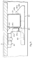
- first conductor parts 1 serve to position the ladder. They each consist in the usual way of two parallel bars 11 and square-shaped rungs 12, which are connected to the bars 11 in a suitable manner.
- a second ladder part 2 is connected to the first ladder parts 1 with the aid of articulated joints 3 so that it assumes its horizontal position of use when the joints 3 stop when the first ladder parts 1 are set up.
- the second ladder part 2 consists of two ladder part segments 2a and 2b, which are connected to one another by a further joint 4, whereby the joint 4 strikes when the two conductor part segments 2a and 2b form a plane.
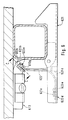
- the ladder section segments 2a and 2b each have two parallel bars 21a and 21b, with which rungs 22a and 22b located between them are fixedly connected. 2, the ladder part segment 2a with its bars 21a and the rungs 22a can also be clearly seen.
- a step plate 5 is located on the rungs 22 in both ladder part segments 2a and 2b. Their width b is somewhat smaller than the clear distance h between the spars 21 (FIG. 2).
- the tread plates 5 are expediently provided with a non-slip and, if appropriate, moisture-sealed covering, so that they are largely insensitive to moisture, grease or oil and offer a secure stand.
- Each of the tread plates 5 is connected to two rungs 22; for this purpose, holding fittings 61 and 62 are rigidly fastened on the side 51 of the step plates 5 facing the rungs 22, in such a way that they are on both sides of the Central axis 52 and are arranged outside of this.
- the holding fittings 61 and 62 are shown enlarged in FIGS. 3 to 5.
- FIG. 3 and 4 show a sectional front and bottom view of the arrangement of a retaining fitting 61 of the step plate 5.
- a retaining tab 611 is rigidly attached to the side 51 of the step plate 5 with two screws 612 or in another suitable manner.
- a Z-shaped holding hook 613 is pivotally mounted in the holding tab 611.
- the holding hook 613 has a circular cross section Q, as is indicated in FIG. 4. It consists in one piece of a first holding piece 613a, which is rotatable in the holding tab 611 about the axis of rotation of its cross section, but cannot be displaced longitudinally, of a second holding piece 613b and a web 613c connecting the two holding pieces 613a and 613b.
- the angled holding piece 613b rests on a holding surface 221 of a first rung 22, which lies opposite the contact surface 222 of the rung 22 on the tread plate 5 and is parallel.
- the arrangement is such that the axes of the holding pieces 613a and 613b are always parallel to the spars 11.
- the holding tab 611 is provided with a bearing piece 611a, which has a slot-shaped recess 611b.
- this recess 611b which is arranged transversely to the axis of the bearing piece (611a), there is an embossing 613d of the holding hook 613, which is provided on the circumference of the holding piece 613a; it can also be a weld bead.
- a holding fitting 62 is provided with a lock 621 for the associated rung 22.
- both the retaining hook 613 and the retaining tab 611 are identical to the embodiment of the retaining bracket 61 according to FIGS. 3 and 4, in which a locking is not provided.
- the lock 621 is pivotable about an axis 622, which is provided in the retaining hook 613 is.
- the axis 622 is shown schematically in the drawing because its detailed design is relatively arbitrary. It is only necessary to ensure that the lock 621, on one side of which a locking hook 621a is provided, can be pivoted about the holding hook 613 in such a way that a locking surface 621b clamps the rung 22 on the web 613c.
- a spring 623 ensures that the lock 621 always maintains this position in the operating state without external influence.
- the locking hook 621a is also provided with an insertion slope 621c, so that when the tread plate 5 is inserted into the ladder part 2, the latch 621 is lifted off the rung 22 against the action of the spring 623 before it slides into the locking position shown in FIG. 5 .
- the lock 621 is U-shaped, so that locking hooks 621a are formed on both belts of the lock 621.
- the spring 623 designed as a leaf spring loads the web of the lock 621. It is understood that the straps of the lock 621 are spaced apart from one another at least to such an extent that the retaining hook 613 can be overlapped.
- a stop 613e is provided on its web 613c, which together with the spring 623 forms a single stamped and bent part.
- This stamped and bent part is fastened, for example, by means of clamping to the web 613c, which has a further embossing 613f, which serves as a stop for the stamped and bent part.
- All holding hooks 613 of a tread plate 5 are always aligned in terms of their Z-shape. This makes it possible to push the tread plate 5 including its retaining fittings 61 and 62 from one side over the webs 22 of the conductor part 2; the lock 621 engages so that, regardless of whether the tread plate 5 is placed on the webs 22 or is attached to it, the tread plate 5 is securely fastened. Still, it's in simpler Can be dismantled by releasing the lock 621. As in particular FIGS.
- a spring wire is now used as spring 623, the first, freely resilient end 623a of which is locked to a saddle 613g of the holding piece 613.
- the saddle 613g is easily created by pressure deformation of the (possibly also tubular) holding piece 613, in which a flat pressure surface 613h is also formed. 7, these changes in shape can be formed on both sides.
- the stop 621d can also be obtained from the web of the latch 621 by means of a tear.
- the corresponding details are customary in the art and are therefore only indicated in the drawing.
- FIG. 7 shows an embodiment modified again from that of FIG. 6, in which a somewhat modified spring 623 'is arranged, which in the area of the section CC is identical to the variant according to FIG. 6, but the second end 623d' thereof abuts the stop 621d ', which also limits the pivoting range of the lock 621.
- space is now also created for execution as a torsion spring.
Landscapes
- Engineering & Computer Science (AREA)
- Architecture (AREA)
- Mechanical Engineering (AREA)
- Civil Engineering (AREA)
- Structural Engineering (AREA)
- Ladders (AREA)
Applications Claiming Priority (4)
| Application Number | Priority Date | Filing Date | Title |
|---|---|---|---|
| DE9209912U DE9209912U1 (de) | 1992-07-23 | 1992-07-23 | Trittplatte für Leitern |
| DE9209912U | 1992-07-23 | ||
| DE9217419U | 1992-12-19 | ||
| DE9217419U DE9217419U1 (de) | 1992-07-23 | 1992-12-19 | Trittplatte für Leitern |
Publications (1)
| Publication Number | Publication Date |
|---|---|
| EP0580960A1 true EP0580960A1 (fr) | 1994-02-02 |
Family
ID=25959731
Family Applications (1)
| Application Number | Title | Priority Date | Filing Date |
|---|---|---|---|
| EP93106128A Withdrawn EP0580960A1 (fr) | 1992-07-23 | 1993-04-15 | Plate-forme pour échelle |
Country Status (7)
| Country | Link |
|---|---|
| US (1) | US5358069A (fr) |
| EP (1) | EP0580960A1 (fr) |
| CA (1) | CA2095771A1 (fr) |
| CZ (1) | CZ109993A3 (fr) |
| DE (1) | DE9217419U1 (fr) |
| HU (1) | HUT66723A (fr) |
| PL (1) | PL299740A1 (fr) |
Cited By (3)
| Publication number | Priority date | Publication date | Assignee | Title |
|---|---|---|---|---|
| EP0702120A1 (fr) * | 1994-09-19 | 1996-03-20 | Michel Goubaud | Elément de plancher pour platelage d'échafaudage |
| AU686081B3 (en) * | 1997-04-04 | 1998-01-29 | Dofair Company Ltd | Mountable work platform for a ladder |
| WO2023084078A1 (fr) | 2021-11-12 | 2023-05-19 | Lampe Holding B.V. | Ensemble comprenant une échelle pliante et une plateforme |
Families Citing this family (17)
| Publication number | Priority date | Publication date | Assignee | Title |
|---|---|---|---|---|
| US5711400A (en) * | 1997-04-02 | 1998-01-27 | Tan; Su-Fen | Mountable work platform for a ladder |
| DE19923765C2 (de) * | 1999-05-22 | 2001-05-31 | Horst Laug | Leiter mit Diele |
| US7086500B2 (en) * | 2003-10-31 | 2006-08-08 | Wing Enterprises, Inc. | Extensible, self locking platform and method of using same |
| CA2531430C (fr) * | 2005-12-23 | 2013-10-08 | Etobicoke Ironworks Limited | Plate-forme et crochet autobloquant d'echafaudage |
| US8136632B2 (en) * | 2008-07-10 | 2012-03-20 | Edward J. Gabriel | Collapsible platform assembly for a ladder |
| US8800718B2 (en) * | 2008-12-30 | 2014-08-12 | Allred & Associates Inc. | Ultra lightweight segmented ladder/bridge system |
| US8448748B2 (en) | 2008-12-30 | 2013-05-28 | Allred & Associates, Inc. | Ultra lightweight segmented ladder/bridge system |
| US8381873B2 (en) * | 2009-07-28 | 2013-02-26 | Affinity Tool Works | Ladder and support stand |
| US9284776B2 (en) * | 2009-10-19 | 2016-03-15 | William Ralph Bond | Entertainment table |
| EP2769752B1 (fr) * | 2011-10-17 | 2016-09-14 | Ildefonso Aral Diaz | Dispositif de gymnastique |
| US10492471B2 (en) * | 2015-06-12 | 2019-12-03 | Eco Sports Group, Inc. | Hill climbing apparatus for pet training and fitness |
| US10701901B2 (en) | 2015-06-12 | 2020-07-07 | Eco Sports Group, Inc. | Self-tipping hurdles for pet training and fitness |
| US9926743B1 (en) | 2016-10-04 | 2018-03-27 | Julie Eatmon | Ladder convertible to a scaffold |
| US10145128B2 (en) * | 2016-12-16 | 2018-12-04 | Werner Co. | Interlocking work platform system and method |
| CN207436473U (zh) * | 2017-08-04 | 2018-06-01 | 苏州飞华铝制工业有限公司 | 工作台梯柱的解锁结构 |
| CN107981602A (zh) * | 2017-12-11 | 2018-05-04 | 天津市金锚家居用品有限公司 | 一种组合式梯凳 |
| US12497789B2 (en) * | 2021-03-02 | 2025-12-16 | Werner Co. | Interlocking work platform system |
Citations (7)
| Publication number | Priority date | Publication date | Assignee | Title |
|---|---|---|---|---|
| US2054690A (en) * | 1935-08-30 | 1936-09-15 | Charles A Barrett | Trestle ladder lock |
| GB2042040A (en) * | 1978-05-30 | 1980-09-17 | Inventec Patents Ltd | Foldable step-stool |
| GB2089873A (en) * | 1980-12-23 | 1982-06-30 | Wickramasuriya Damasius Benett | Convertible ladder |
| DE3505917A1 (de) * | 1985-02-21 | 1986-08-21 | Krause-Werk Gmbh & Co Kg, 6320 Alsfeld | Arbeitsbuehne |
| US4648481A (en) * | 1986-04-21 | 1987-03-10 | Alpha Metal Corp. | Multipurpose aluminum folding ladder equipped with a detachable stand-on board and supporting handrails |
| DE3627303A1 (de) * | 1986-08-12 | 1988-02-18 | Geis & Knoblauch Gmbh & Co Kg | Steiggeraet |
| DE8906444U1 (de) * | 1989-05-25 | 1989-07-13 | Gröning, Klaus J., 7000 Stuttgart | Als Gangway für Wasserfahrzeuge ausgebildete Vorrichtung |
Family Cites Families (10)
| Publication number | Priority date | Publication date | Assignee | Title |
|---|---|---|---|---|
| US570661A (en) * | 1896-11-03 | Step or extension ladder | ||
| US445453A (en) * | 1891-01-27 | Ladder | ||
| CA691590A (en) * | 1964-07-28 | J. Tucker Maurice | Platforms | |
| US2430642A (en) * | 1944-07-28 | 1947-11-11 | Mahaffey Jesse Lynn | Safety trestle |
| DE854996C (de) * | 1951-05-29 | 1952-11-10 | Hans Poehlmann | Als Bockgeruest verwendbare Doppelstehleiter mit Laufbrett |
| GB1250781A (fr) * | 1967-12-13 | 1971-10-20 | ||
| JPS63204735A (ja) * | 1987-02-20 | 1988-08-24 | Mitsubishi Electric Corp | 半導体装置のパツケ−ジ構造 |
| JP2609894B2 (ja) * | 1988-02-25 | 1997-05-14 | トーワ株式会社 | 被封止部品のトランスファ樹脂封止成形方法とこれに用いられる樹脂封止成形用金型装置及びフィルムキャリア |
| JPH0290632A (ja) * | 1988-09-28 | 1990-03-30 | Matsushita Electron Corp | 半導体装置の樹脂封止装置 |
| US5056620A (en) * | 1990-04-23 | 1991-10-15 | Zumwalt Donald A | Stepladder platform |
-
1992
- 1992-12-19 DE DE9217419U patent/DE9217419U1/de not_active Expired - Lifetime
-
1993
- 1993-04-15 EP EP93106128A patent/EP0580960A1/fr not_active Withdrawn
- 1993-04-19 HU HU9301154A patent/HUT66723A/hu unknown
- 1993-05-05 US US08/056,876 patent/US5358069A/en not_active Expired - Fee Related
- 1993-05-07 CA CA002095771A patent/CA2095771A1/fr not_active Abandoned
- 1993-06-07 CZ CZ931099A patent/CZ109993A3/cs unknown
- 1993-07-20 PL PL29974093A patent/PL299740A1/xx unknown
Patent Citations (7)
| Publication number | Priority date | Publication date | Assignee | Title |
|---|---|---|---|---|
| US2054690A (en) * | 1935-08-30 | 1936-09-15 | Charles A Barrett | Trestle ladder lock |
| GB2042040A (en) * | 1978-05-30 | 1980-09-17 | Inventec Patents Ltd | Foldable step-stool |
| GB2089873A (en) * | 1980-12-23 | 1982-06-30 | Wickramasuriya Damasius Benett | Convertible ladder |
| DE3505917A1 (de) * | 1985-02-21 | 1986-08-21 | Krause-Werk Gmbh & Co Kg, 6320 Alsfeld | Arbeitsbuehne |
| US4648481A (en) * | 1986-04-21 | 1987-03-10 | Alpha Metal Corp. | Multipurpose aluminum folding ladder equipped with a detachable stand-on board and supporting handrails |
| DE3627303A1 (de) * | 1986-08-12 | 1988-02-18 | Geis & Knoblauch Gmbh & Co Kg | Steiggeraet |
| DE8906444U1 (de) * | 1989-05-25 | 1989-07-13 | Gröning, Klaus J., 7000 Stuttgart | Als Gangway für Wasserfahrzeuge ausgebildete Vorrichtung |
Cited By (4)
| Publication number | Priority date | Publication date | Assignee | Title |
|---|---|---|---|---|
| EP0702120A1 (fr) * | 1994-09-19 | 1996-03-20 | Michel Goubaud | Elément de plancher pour platelage d'échafaudage |
| FR2724679A1 (fr) * | 1994-09-19 | 1996-03-22 | Goubaud Michel | Element de plancher pour platelage d'echafaudage |
| AU686081B3 (en) * | 1997-04-04 | 1998-01-29 | Dofair Company Ltd | Mountable work platform for a ladder |
| WO2023084078A1 (fr) | 2021-11-12 | 2023-05-19 | Lampe Holding B.V. | Ensemble comprenant une échelle pliante et une plateforme |
Also Published As
| Publication number | Publication date |
|---|---|
| CZ109993A3 (en) | 1994-02-16 |
| PL299740A1 (en) | 1994-01-24 |
| HUT66723A (en) | 1994-12-28 |
| CA2095771A1 (fr) | 1994-01-24 |
| US5358069A (en) | 1994-10-25 |
| DE9217419U1 (de) | 1993-03-25 |
| HU9301154D0 (en) | 1993-09-28 |
Similar Documents
| Publication | Publication Date | Title |
|---|---|---|
| EP0580960A1 (fr) | Plate-forme pour échelle | |
| EP0425786B1 (fr) | Echelle | |
| DE2732654A1 (de) | Gelenkbeschlag fuer leiterteile | |
| DE2637974C2 (de) | Zusammenlegbarer Kindersitz für eine Einkaufskarre | |
| DE1812628A1 (de) | Mehrteilige Leiter | |
| DE3223643A1 (de) | Wandverankerungsvorrichtung | |
| WO2000009850A1 (fr) | Dispositif anti-derapage pour echelles | |
| DE8811070U1 (de) | Leiterpodest | |
| DE29707101U1 (de) | Verstellbare Leiter | |
| EP1338723A2 (fr) | Dispositif de montage d'un garde-corps temporaire d'échafaudage | |
| EP1110482B1 (fr) | Système de guidage et système à rouleaux d'un tiroir | |
| DE69405953T2 (de) | Leiter | |
| EP0310884B1 (fr) | Echelle repliable | |
| DE3505917C2 (fr) | ||
| DE112021002851T5 (de) | Sicherheitsleiter | |
| DE202015103639U1 (de) | Mehrteilige Leiter | |
| DE1434946A1 (de) | Ausziehbare Tragkonstruktion | |
| DE102021211507A1 (de) | Stiel | |
| EP3431700B1 (fr) | Protection contre le basculement pour échelles | |
| DE8504805U1 (de) | Arbeitsbühne | |
| DE3132294C2 (de) | An einer Vorrichtung insbesondere an einem Fahrzeug angebrachte Leiter | |
| DE2748113C2 (fr) | ||
| DE9209912U1 (de) | Trittplatte für Leitern | |
| DE3923815A1 (de) | Geruest | |
| DE20006754U1 (de) | Trittleiter |
Legal Events
| Date | Code | Title | Description |
|---|---|---|---|
| PUAI | Public reference made under article 153(3) epc to a published international application that has entered the european phase |
Free format text: ORIGINAL CODE: 0009012 |
|
| AK | Designated contracting states |
Kind code of ref document: A1 Designated state(s): AT BE CH DE DK ES FR GB GR IE IT LI LU MC NL PT SE |
|
| 17P | Request for examination filed |
Effective date: 19940223 |
|
| 17Q | First examination report despatched |
Effective date: 19960402 |
|
| 18W | Application withdrawn |
Withdrawal date: 19960418 |