EP0580983A1 - Elektrische Vielfach-Steckverbindung - Google Patents
Elektrische Vielfach-Steckverbindung Download PDFInfo
- Publication number
- EP0580983A1 EP0580983A1 EP93108483A EP93108483A EP0580983A1 EP 0580983 A1 EP0580983 A1 EP 0580983A1 EP 93108483 A EP93108483 A EP 93108483A EP 93108483 A EP93108483 A EP 93108483A EP 0580983 A1 EP0580983 A1 EP 0580983A1
- Authority
- EP
- European Patent Office
- Prior art keywords
- lever
- connector
- engaged
- card
- engaging portion
- Prior art date
- Legal status (The legal status is an assumption and is not a legal conclusion. Google has not performed a legal analysis and makes no representation as to the accuracy of the status listed.)
- Granted
Links
Images



Classifications
-
- G—PHYSICS
- G06—COMPUTING OR CALCULATING; COUNTING
- G06K—GRAPHICAL DATA READING; PRESENTATION OF DATA; RECORD CARRIERS; HANDLING RECORD CARRIERS
- G06K13/00—Conveying record carriers from one station to another, e.g. from stack to punching mechanism
- G06K13/02—Conveying record carriers from one station to another, e.g. from stack to punching mechanism the record carrier having longitudinal dimension comparable with transverse dimension, e.g. punched card
- G06K13/08—Feeding or discharging cards
- G06K13/0806—Feeding or discharging cards using an arrangement for ejection of an inserted card
-
- G—PHYSICS
- G06—COMPUTING OR CALCULATING; COUNTING
- G06K—GRAPHICAL DATA READING; PRESENTATION OF DATA; RECORD CARRIERS; HANDLING RECORD CARRIERS
- G06K13/00—Conveying record carriers from one station to another, e.g. from stack to punching mechanism
- G06K13/02—Conveying record carriers from one station to another, e.g. from stack to punching mechanism the record carrier having longitudinal dimension comparable with transverse dimension, e.g. punched card
- G06K13/08—Feeding or discharging cards
-
- H—ELECTRICITY
- H01—ELECTRIC ELEMENTS
- H01R—ELECTRICALLY-CONDUCTIVE CONNECTIONS; STRUCTURAL ASSOCIATIONS OF A PLURALITY OF MUTUALLY-INSULATED ELECTRICAL CONNECTING ELEMENTS; COUPLING DEVICES; CURRENT COLLECTORS
- H01R12/00—Structural associations of a plurality of mutually-insulated electrical connecting elements, specially adapted for printed circuits, e.g. printed circuit boards [PCB], flat or ribbon cables, or like generally planar structures, e.g. terminal strips, terminal blocks; Coupling devices specially adapted for printed circuits, flat or ribbon cables, or like generally planar structures; Terminals specially adapted for contact with, or insertion into, printed circuits, flat or ribbon cables, or like generally planar structures
- H01R12/70—Coupling devices
- H01R12/7005—Guiding, mounting, polarizing or locking means; Extractors
-
- H—ELECTRICITY
- H01—ELECTRIC ELEMENTS
- H01R—ELECTRICALLY-CONDUCTIVE CONNECTIONS; STRUCTURAL ASSOCIATIONS OF A PLURALITY OF MUTUALLY-INSULATED ELECTRICAL CONNECTING ELEMENTS; COUPLING DEVICES; CURRENT COLLECTORS
- H01R13/00—Details of coupling devices of the kinds covered by groups H01R12/70 or H01R24/00 - H01R33/00
- H01R13/62—Means for facilitating engagement or disengagement of coupling parts or for holding them in engagement
- H01R13/629—Additional means for facilitating engagement or disengagement of coupling parts, e.g. aligning or guiding means, levers, gas pressure electrical locking indicators, manufacturing tolerances
- H01R13/633—Additional means for facilitating engagement or disengagement of coupling parts, e.g. aligning or guiding means, levers, gas pressure electrical locking indicators, manufacturing tolerances for disengagement only
-
- H—ELECTRICITY
- H01—ELECTRIC ELEMENTS
- H01R—ELECTRICALLY-CONDUCTIVE CONNECTIONS; STRUCTURAL ASSOCIATIONS OF A PLURALITY OF MUTUALLY-INSULATED ELECTRICAL CONNECTING ELEMENTS; COUPLING DEVICES; CURRENT COLLECTORS
- H01R12/00—Structural associations of a plurality of mutually-insulated electrical connecting elements, specially adapted for printed circuits, e.g. printed circuit boards [PCB], flat or ribbon cables, or like generally planar structures, e.g. terminal strips, terminal blocks; Coupling devices specially adapted for printed circuits, flat or ribbon cables, or like generally planar structures; Terminals specially adapted for contact with, or insertion into, printed circuits, flat or ribbon cables, or like generally planar structures
- H01R12/70—Coupling devices
- H01R12/71—Coupling devices for rigid printing circuits or like structures
- H01R12/712—Coupling devices for rigid printing circuits or like structures co-operating with the surface of the printed circuit or with a coupling device exclusively provided on the surface of the printed circuit
- H01R12/714—Coupling devices for rigid printing circuits or like structures co-operating with the surface of the printed circuit or with a coupling device exclusively provided on the surface of the printed circuit with contacts abutting directly the printed circuit; Button contacts therefore provided on the printed circuit
Definitions
- the present invention relates to a multipolar electrical connector (hereinafter referred to as multipolar connector) for connecting multipolar contacts of a card which belongs to the field of IC memory cards or the like, to multipolar contacts of a computer or the like.
- multipolar connector a multipolar electrical connector for connecting multipolar contacts of a card which belongs to the field of IC memory cards or the like, to multipolar contacts of a computer or the like.
- the multipolar connector is also required to be as thin as 5 to 6 mm.
- a card ejecting mechanism is often disposed to enhance the maneuverability for rearwardly pushing and removing the card which has been set in the connector.
- a thin multipolar connector having a card ejecting mechanism is known in U.S. Pat. 5,139,435.
- the multipolar connector in U.S. Pat. 5,139,435 comprises: a connector body having a contact-piece group; guides rearwardly extending from the connector body at the ends of both lateral sides thereof; a reinforcing plate-like frame extending between the left- and right-hand guides at the undersides thereof; a lever disposed along one of the guides and movable in the back to forth direction of the connector; and a card pushing cam pin-connected to the connector body, a predetermined portion of the cam being relatively rotatably connected to the front end of the lever.
- the card ejecting mechanism comprises the lever and the cam.
- This ejecting mechanism is operated in the following manner.
- the lever is forwardly pushed to rotate the cam, a card pushing portion of the cam is rearwardly moved.
- the front end of the card which has been set in the connector is rearwardly pushed by the card pushing portion, so that a contact-piece group of the card is separated from the contact-piece group of the connector body, causing the card to be rearwardly pushed out.
- a portable electronic device such as a portable personal computer on which such a thin multipolar connector is mounted
- the lever forming the ejecting mechanism is movable in the back and forth direction of the connector and the cam is swingable around the pin-connection part thereof. Accordingly, while the user carries the electronic device, the device may be vibrated so that the lever is freely moved in the back and forth direction of the connector or the cam is freely swung. This disadvantageously produces an unpleasant clacking noise.
- a multipolar connector to be used for a card such as an IC memory card
- Such trouble can be solved by discharging static electricity charged on the card from the earth terminals thereof to the printed circuit board or the like through the earth terminals of the multipolar connector.
- the plate-like frame extending between the left- and right-hand guides at the undersides thereof is provided on the flat-plate portion thereof with earth contact pieces, and these earth contact pieces are adapted to come in contact with earth-terminal corresponding portions of the card at the underside tehreof.
- the present invention provides a multipolar connector having: a connector body; a contact-piece group disposed in the connector body; left- and right-hand guide members respectively projecting from the left-and right-hand ends of the connector body in the rearward direction of the connector; guide grooves formed in the left- and right-hand guide members and adapted to guide, in the back and forth direction of the connector, a card with the lateral edges thereof fitted in the guide grooves, the card being provided at the front end thereof with a contact-piece group corresponding to the contact-piece group of the connector; and a frame disposed as extending between the left-and right-hand guide members at the undersides thereof, and the present invention is characterized by comprising: a cam swingably pin-connected to the connector body; a card pushing portion formed at a part of the cam and adapted to go in and out from a position of the front end side of a card setting space between the left- and right-hand guide members when the cam is swung; a lever disposed along one of the left- and right
- the engaging portion having the projecting piece and the expanding portion may be disposed at the side of the lever holding portion, and there may be disposed, at the side of the lever, the portion to be engaged adapted such that, when the lever is pushed out in the rearward direction, the expanding portion overlaps the portion to be engaged, causing the projecting piece to be resiliently displaced and that, when the lever is pushed in the forward direction, the overlaping state of the expanding portion on the portion to be engaged is released to allow the projecting piece to be resiliently reset.
- the multipolar connector having the arrangement above-mentioned, when the card pushing portion of the cam projects in the position of the front end side of the the card setting space and a card is set as pushed in the card setting space in the forward direction of the connector, the front end surface of the card pushes the card pushing portion in the forward direction to rotate the cam. Accordingly, the card pushing portion is moved in the forward direction from the position of the front end side of the card setting space, causing the lever to be pushed out in the rearward direction. At this time, the portion to be engaged overlaps the expanding portion of the engaging portion and the projecting piece is resiliently displaced.
- the card pushing portion of the cam projects into the position of the front end side of the card setting space so that the front end surface of the card is pushed in the rearward direction to cause the card to be pushed out in the rearward direction.
- the lever is pushed in the forward direction, the overlaping state of the portion to be engaged on the expanding portion is released to allow the projecting piece to be resiliently reset. While the portion to be engaged overlaps the expanding portion of the engaging portion, the projecting piece of the engaging portion is resiliently displaced. Accordingly, at the moment that the overlaping state of the portion to be engaged on the expanding portion is released, the projecting piece of the engaging portion is resiliently reset.
- Such momentary resilient resetting of the projecting piece is transmitted, as a click feel (sound or shock), to the hand through the lever.
- a pleasant click feel can be obtained when the card is pushed out, merely by providing the ejecting mechanism with a single member, i.e., the engaging portion.
- the engaging portion and the portion to be engaged form a locking mechanism arranged such that, when the lever is pushed out in the rearward direction, at least one of the engaging portion and the portion to be engaged is resiliently displaced and overlaps the other portion, and that, when the lever is pushed in the forward direction, the overlaping state is released so that at least one of the engaging portion and the portion to be engaged is resiliently reset and engaged with the other portion.
- the engaging portion and the portion to be engaged are engaged with each other to prevent the lever from being moved in the back and forth direction of the connector. This prevents the lever and the cam from being freely moved, thus producing no unpleasant clacking noise.
- the present invention also provides a multipolar connector having: a connector body; a contact-piece group disposed in the connector body; left- and right-hand guide members respectively projecting from the left- and right-hand ends of the connector body in the rearward direction of the connector; guide grooves formed in the left- and right-hand guide members and adapted to guide, in the back and forth direction of the connector, a card with the lateral edges thereof fitted in the guide grooves, the card being provided at the front end thereof with a contact-piece group corresponding to the contact-piece group of the connector; and a frame disposed as extending between the left- and right-hand guide members at the undersides thereof, and the present invention is characterized by comprising: projecting pieces upwardly standing from the lateral edges of the frame; and earth contact pieces so formed at the projecting pieces as to project into a card setting space between the left- and right-hand guide members from the lateral sides of the card setting space, the earth contact pieces being adapted to come in contact with earth terminals of a card at the lateral sides
- the earth terminals at the lateral sides of a card pushed in the card setting space are adapted to come in contact with the earth contact pieces which are disposed at the frame through the projecting pieces and which project into the card setting space from the lateral sides thereof.
- the present invention can provide a multipolar connector which involves no likelihood that the coating of the underside of a card comes off, even though the multipolar connector has a static electricity discharging function with the frame thereof utilized.
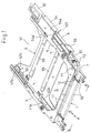
- a connector body 1 is made of an insulating synthetic resin.
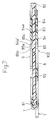
- the connector body 1 has a plurality of holes 11, 12 which are formed at regular pitches and which are respectively located in two, upper and lower, rows. As shown in Figs. 4 and 5, the plurality of holes 11, 12 respectively hold pin-shape contact pieces 21, 22 as projecting in the rearward direction B of the connector. In the pin-shape contact pieces 21, 22, portions thereof projecting from the connector body 1 in the forward direction A form terminal portions 23, 24, respectively.
- the connector body 1 has a comb-like support 13 of which teeth project in the forward direction A. As shown in Fig. 5, the terminal portions 23 in the upper row and the terminal portions 24 in the lower row are introduced, as bent, into spaces 13a between adjacent teeth of the comb-like support 13.
- terminal portions 23 in the upper row are further bent horizontally in the forward direction A in the spaces 13a, and the terminal portions 24 in the lower row are further bent horizontally in the rearward direction B in the spaces 13a, so that the portions thus further bent underlie the underside of the connector body 1.
- the terminal portions 23, 24 are soldered to a printed circuit board 200 at a circuit pattern (not shown) thereof with the surfaces of the terminal portions 23, 24 coming in contact with the surface of the printed circuit board 200.
- the plurality of pin-shape contact pieces 21 in the upper row and the plurality of pin-shape contact pieces 22 in the lower row form a contact-piece group 2.
- a guide member 4 extends in the rearward direction B from the rear end of the connector body 1 at the left side L thereof.
- the guide member 4 is provided in the inner side thereof with a front guide groove 41a and a rear guide groove 41b which extend in the back and forth direction of the connector.
- the front guide groove 41a has a lower wall 42a
- the rear guide groove 41b has a lower wall 42b.
- a guide member 5 extends in the rearward direction B from the rear end of the connector body 1 at the right side R thereof.
- the guide member 5 also has a front guide groove (not shown) and a rear guide groove (not shown) which are respectively symmetrical with respect to the front guide groove 41a and the rear guide groove 41b of the left-hand guide member 4.
- the distance L between the groove bottoms 43, 53 of the guide members 4, 5 in Fig. 4, is substantially equal to the width in the transverse direction of a card C such as an IC memory card or the like. Accordingly, when the lateral edges C1, C2 of the card C are fitted in the guide grooves 41a, 41b of the guide member 4 and the guide grooves (not shown) of the guide member 5, the card C can be securely guided in the back and forth direction of the connector with the edges C1, C2 of the card C prevented from being rickety by the guide grooves of the guide members 4, 5.
- Each of the guide members 4, 5 is slightly longer than the entire length of the card C in the back and forth direction thereof.
- the connector body 1 is provided in the end portion at the right side R thereof with a concave 6.
- This concave 6 is opened into a card setting space S (Fig. 4) formed between the left- and right-hand guide members 4 and 5.
- the concave 6 houses a cam 7 made of synthetic resin.
- the cam 7 is connected to the connector body 1 with a pin 71 such as a rivet.
- the cam 7 has a card pushing portion 72 as projecting therefrom, and an attaching portion 73 to which a lever 8 is connected, the attaching portion 73 being formed at the opposite side of the card pushing portion 72.
- the cam 7 is swingable around the pin 71.
- the card pushing portion 72 is adapted to project to a position (at a right-hand position in this embodiment) P of the front end side of the card setting space S, as shown by a virtual line in Fig. 4, or adapted to be moved in the forward direction A from this position P of the front end side of the card setting space S, as shown in a solid line in Fig. 4.
- the lever 8 has the front end relatively rotatably connected to the attaching portion 73 of the cam 7 with a pin 81 such as a rivet.
- the right-hand guide member 5 integrally has (i) a rearward lever holding portion 54 which is made in the form of a rectangular case and which projects rightward from the guide member 5, and (ii) a forward lever holding portion 55 having an U-shape section.
- the lever 8 as extending along the right-hand guide member 5 is slidably fitted, at two portions thereof, in the lever holding portions 54, 55.
- the lever 8 has an operating portion 82 disposed at a lateral side of and in the immediate vicinity of a card inserting/removing port 51 formed between the left-hand guide member 4 and the right-hand guide member 5.
- the lever 8 is provided at the intermediate part in the back and forth direction thereof with an engaging portion 83.
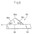
- the engaging portion 83 has (i) a projecting piece 84 which extends in the forward direction A, and (ii) a mountain-shape expanding portion 85 integrally formed at the front end of the projecting piece 84.
- the unit of the projecting piece 84 and the expanding portion 85 is molded integrally with the lever and made in the form of a cantilever as if surroundings thereof are hollowed out from the lever 8. As understood from Fig.
- the expanding portion 85 has a top 85a, a forward inclined surface 85b and a rearward inclined surface 85c, and the forward and rearward inclined surface 85b, 85c respectively have angles of elevation ⁇ 1, ⁇ 2 which are approximately equal to each other and which are not so great with respect to a virtual horizontal plane H.
- the rearward inclined surface 85c of the expanding portion 85 is engaged with the front edge 54a' of the upper wall portion 54a of the rearward lever holding portion 54.
- the engaging portion 83 and the portion to be engaged form a locking mechanism 100.
- the portion to be engaged will be designated by the reference numeral 54a.
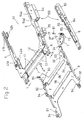
- a frame 9 is provided at the lateral edges thereof with flange pieces 91.
- the frame 9 is also provided at predetermined portions of the lateral edges thereof with upwardly standing projecting pieces 92.
- Earth contact pieces 93 are integrally formed at the projecting pieces 92.
- the frame 9 is also provided at a plurality of portions of the lateral edges thereof with upwardly standing engagement pawls 94.
- the frame 9 is disposed as extending between the left- and right-hand guide members 4, 5 at the undersides thereof. More specifically, the engagement pawls 94 are inserted, from below, into slender grooves 46, 56 respectively formed in the left- and right-hand guide members 4, 5 so that the guide members 4, 5 hold the pawls 94 (Fig. 4).
- the earth contact pieces 93 project into the card setting space S from the lateral sides thereof.
- the frame 9 has a plurality of ribs 95 to enhance the flexural rigidity of the frame 9.
- the card C is provided in the front end surface thereof with pin inserting holes (not shown) which house a contact-piece group corresponding to the contact-piece group 2 of the connector body 1.
- the card C is also provided at the lateral sides thereof with earth terminals E (Fig. 4).
- the card C when, with the lateral edges C1, C2 of the card C guided by the guide grooves 41a, 41b of the left-hand guide member 4 and the guide grooves (not shown) of the right-hand guide member 5, the card C is inserted into the card setting space S so that the contact-piece group of the card C comes in resilient contact with the contact-piece group 2 of the connector body 1, the card C is set at the proper position in the card setting space S.
- the card pushing portion 72 of the cam 7 is moved in the forward direction A from the card setting space S and the lever 8 is pushed out in the rearward direction B (shown by the solid line in Figs. 1 and 4 and also shown in Fig. 6).
- the operating portion 82 For removing the card C from the connector, the operating portion 82 is pushed with a finger of the user to push the lever 8 in the forward direction A, causing the cam 7 to be swung around the pin 71. Accordingly, the cam 7 is swung so that the card pushing portion 72 projects into the front-side position P of the card setting space S as shown by the virtual line in Fig. 4. At this time, the front end surface C3 of the card C is pushed by the card pushing portion 72. Accordingly, while guided by the left- and right-hand guide members 4, 5, the card C is pushed out in the rearward direction B by a distance corresponding to the projecting distance of the card pushing portion 72 into the card setting space S.
- the card pushing portion 72 which has projected into the card setting space S, is pushed by the front end surface C3 of the card C and therefore moved in the forward direction A away from the card setting space S, causing the lever 8 to be pushed out in the rearward direction B.
- the lever 8 is pushed in the rearward direction B in such a manner, the rearward inclined surface 85c of the expanding portion 85 of the engaging portion 83 is slided on the front edge 54a' of the portion to be engaged 54a. Accordingly, the projecting piece 84 is downwardly bent and the expanding portion 85 of the engaging portion 83 underlies the portion to be engaged 54a.
- the earth contact pieces 93 of the frame 9 are rubbed with the lateral sides of the card C and come in contact with the earth terminals E disposed thereat.
- the frame 9 is useful in preventing the guide members 4, 5 made of synthetic resin from being outwardly turned, because the engagement pawls 94 of the frame 9 are inserted into the slender grooves 46, 56 in the left- and right-hand guide members 4, 5.
- the frame 9 is disposed as extending between the left- and right-hand guide members 4, 5 at the undersides thereof, an opening is formed between the left- and right-hand guide members 4, 5 at the tops thereof.
- the card C in Fig. 9 has a bulky portion C4 incorporating, for example, a mass storage such as a hard disk. If the card setting space in a multipolar connector is closed, at the top and underside thereof, by frames or the like, the card C in Fig. 9 cannot be applied to such a multipolar connector, because the bulky portion C4 gets in the way. However, such a card can be applied to the multipolar connector of the embodiment.
- the lateral edges C1, C2 of the main body C5 can be fitted in the guide grooves of the left- and right-hand guide members 4, 5 with the bulky portion C4 passing through and upwardly projecting from the opening formed between the tops of the guide members 4, 5.
- the bulky portion C4 does not get in the way.
- the engaging portion 83 comprises the projecting piece 84 extending in the forward direction A and the mountain-shape expanding portion 85 integrally formed at the front end of the projecting piece 84. That is, the unit of the projecting piece 84 and the expanding portion 85 is molded integrally with the lever and made in the form of a cantilever as if surroundings thereof are hollowed out from the lever 8. Accordingly, the engaging portion 83 can be formed integrally and simultaneously with the formation of the lever 8. However, the engaging portion may be made independently from the lever, and then attached thereto.
- the engaging portion may be formed by a leaf spring having (i) a projecting piece corresponding to the projecting piece 84 and (ii) a mountain-shape expanding portion which corresponds to the expanding portion 85 and which is formed at the front end of the projecting piece by bending the same.
- the engaging portion may be formed by a steel ball held at a fixed position at either the lever side or the side of the upper wall portion 54a of the rearward lever holding portion 54. In this case, the other side may have a concave which the steel ball is adapted to overlap as fitted therein.
- provision may be made such that, when the lever is pushed in the forward direction A, the steel ball is fitted in and overlaps the concave and that, when the lever is pushed out in the rearward direction B, the steel ball comes off from the concave.
- provision may be made such that the steel ball is resiliently biased by a spring and that the steel ball is momentarily pushed in the concave by the resilient force of the spring.
- the engaging portion 83 is formed at the side of the lever 8 and the portion to be engaged 54a is formed at the side of the rearward lever holding portion 54.
- the engaging portion may be formed at the side of the rearward lever holding portion and the portion to be engaged may be formed at the side of the lever.
Landscapes
- Physics & Mathematics (AREA)
- General Physics & Mathematics (AREA)
- Engineering & Computer Science (AREA)
- Theoretical Computer Science (AREA)
- Details Of Connecting Devices For Male And Female Coupling (AREA)
- Coupling Device And Connection With Printed Circuit (AREA)
Applications Claiming Priority (2)
| Application Number | Priority Date | Filing Date | Title |
|---|---|---|---|
| JP1992053910U JP2596687Y2 (ja) | 1992-07-31 | 1992-07-31 | 多極コネクタ |
| JP53910/92 | 1992-07-31 |
Publications (2)
| Publication Number | Publication Date |
|---|---|
| EP0580983A1 true EP0580983A1 (de) | 1994-02-02 |
| EP0580983B1 EP0580983B1 (de) | 1996-09-18 |
Family
ID=12955875
Family Applications (1)
| Application Number | Title | Priority Date | Filing Date |
|---|---|---|---|
| EP93108483A Expired - Lifetime EP0580983B1 (de) | 1992-07-31 | 1993-05-26 | Elektrische Vielfach-Steckverbindung |
Country Status (4)
| Country | Link |
|---|---|
| US (1) | US5299946A (de) |
| EP (1) | EP0580983B1 (de) |
| JP (1) | JP2596687Y2 (de) |
| DE (1) | DE69304834T2 (de) |
Cited By (7)
| Publication number | Priority date | Publication date | Assignee | Title |
|---|---|---|---|---|
| DE29506344U1 (de) * | 1995-04-12 | 1995-08-03 | Stocko Metallwarenfabriken Henkels Und Sohn Gmbh & Co, 42327 Wuppertal | Kontaktiereinheit für kartenförmige Trägerelemente |
| EP0678824A1 (de) * | 1994-03-09 | 1995-10-25 | Molex Incorporated | Allgemein einsetzbare Auswurfvorrichtung für einen IC-Kartenverbinder |
| GB2288924A (en) * | 1994-04-28 | 1995-11-01 | Whitaker Corp | Card edge connector with ejection mechanism |
| EP0681350A1 (de) * | 1994-04-18 | 1995-11-08 | Japan Aviation Electronics Industry, Limited | Steckverbindung mit Druckknopf für einen Steuerhebel |
| FR2740267A1 (fr) * | 1995-10-19 | 1997-04-25 | Japan Aviation Electron | Connecteur electrique muni d'un actionneur a came, pour un grand nombre de contacts |
| WO2001029934A1 (en) * | 1999-10-20 | 2001-04-26 | Itt Manufacturing Enterprises Inc. | Electrical connector for a smart card, having a lever and a pusher for ejecting the card |
| EP1118955A3 (de) * | 1999-12-22 | 2002-04-24 | Tyco Electronics AMP K.K. | Kartenverbinder |
Families Citing this family (14)
| Publication number | Priority date | Publication date | Assignee | Title |
|---|---|---|---|---|
| JP2562766Y2 (ja) * | 1992-11-18 | 1998-02-16 | ケル株式会社 | 多段式メモリーカード用コネクタ |
| JPH07272793A (ja) * | 1994-03-10 | 1995-10-20 | Whitaker Corp:The | カードコネクタ及びそのカード排出機構 |
| US5613860A (en) * | 1994-12-14 | 1997-03-25 | Molex Incorporated | Universal grounding clip for card-receiving connector |
| JP3213872B2 (ja) * | 1994-12-28 | 2001-10-02 | モレックス インコーポレーテッド | 携帯電話に於ける電話情報カードドライブ装置 |
| US5588850A (en) * | 1995-08-08 | 1996-12-31 | Tongrand Limited | Grounding means for memory card connector |
| US7014118B1 (en) | 1997-10-10 | 2006-03-21 | Robinson Nugent, Inc | Module header apparatus |
| TW347925U (en) * | 1997-10-23 | 1998-12-11 | Hon Hai Prec Ind Co Ltd | Card-retreating structure for connector of electronic card |
| US6561826B2 (en) * | 2001-06-08 | 2003-05-13 | Tellabs Operations, Inc. | Circuit board having an emission reducing ejector |
| JP4078167B2 (ja) * | 2002-09-25 | 2008-04-23 | ホシデン株式会社 | カードコネクタ |
| JP2004146168A (ja) * | 2002-10-23 | 2004-05-20 | Jst Mfg Co Ltd | コネクタ |
| US20090077293A1 (en) * | 2007-09-07 | 2009-03-19 | International Business Machines Corporation | Dimm Ejection Mechanism |
| US9064200B2 (en) * | 2011-01-31 | 2015-06-23 | Apple Inc. | Flat object ejector assembly |
| CN202712549U (zh) * | 2012-07-02 | 2013-01-30 | 番禺得意精密电子工业有限公司 | 插座连接器 |
| TWI806513B (zh) * | 2022-03-23 | 2023-06-21 | 緯創資通股份有限公司 | 殼體組件與包括其之電子裝置 |
Citations (3)
| Publication number | Priority date | Publication date | Assignee | Title |
|---|---|---|---|---|
| US4533196A (en) * | 1981-09-19 | 1985-08-06 | Krone Gmbh | Device for making a solderless, non-screwed and unstripped single or multiple contact at a terminal element |
| WO1988008212A1 (fr) * | 1987-04-04 | 1988-10-20 | Trw Daut + Rietz Gmbh & Co. Kg | Dispositif de couplage electrique |
| US5026296A (en) * | 1990-03-05 | 1991-06-25 | Japan Aviation Electronics Industry, Limited | Electrical connector equipped with release mechanism |
Family Cites Families (3)
| Publication number | Priority date | Publication date | Assignee | Title |
|---|---|---|---|---|
| JPH0517826Y2 (de) * | 1988-07-29 | 1993-05-12 | ||
| US5139435A (en) * | 1990-12-04 | 1992-08-18 | Hosiden Corporation | Multipolar electrical connector |
| US5197894A (en) * | 1991-05-30 | 1993-03-30 | Japan Aviation Electronics Industry, Limited | Electrical connector equipped with a release mechanism |
-
1992
- 1992-07-31 JP JP1992053910U patent/JP2596687Y2/ja not_active Expired - Fee Related
-
1993
- 1993-05-24 US US08/065,066 patent/US5299946A/en not_active Expired - Lifetime
- 1993-05-26 EP EP93108483A patent/EP0580983B1/de not_active Expired - Lifetime
- 1993-05-26 DE DE69304834T patent/DE69304834T2/de not_active Expired - Lifetime
Patent Citations (3)
| Publication number | Priority date | Publication date | Assignee | Title |
|---|---|---|---|---|
| US4533196A (en) * | 1981-09-19 | 1985-08-06 | Krone Gmbh | Device for making a solderless, non-screwed and unstripped single or multiple contact at a terminal element |
| WO1988008212A1 (fr) * | 1987-04-04 | 1988-10-20 | Trw Daut + Rietz Gmbh & Co. Kg | Dispositif de couplage electrique |
| US5026296A (en) * | 1990-03-05 | 1991-06-25 | Japan Aviation Electronics Industry, Limited | Electrical connector equipped with release mechanism |
Non-Patent Citations (2)
| Title |
|---|
| PATENT ABSTRACTS OF JAPAN, unexamined applications, E section, vol. 16, no. 138, April 07, 1992 THE PATENT OFFICE JAPANESE GOVERNMENT page 39 E 1186 * |
| SOVIET INVENTIONS ILLUSTRATED, X section, week 9029, August 29, 1990 DERWENT PUBLICATIONS LTD, London * |
Cited By (12)
| Publication number | Priority date | Publication date | Assignee | Title |
|---|---|---|---|---|
| EP0678824A1 (de) * | 1994-03-09 | 1995-10-25 | Molex Incorporated | Allgemein einsetzbare Auswurfvorrichtung für einen IC-Kartenverbinder |
| EP0681350A1 (de) * | 1994-04-18 | 1995-11-08 | Japan Aviation Electronics Industry, Limited | Steckverbindung mit Druckknopf für einen Steuerhebel |
| US5660552A (en) * | 1994-04-18 | 1997-08-26 | Japan Aviation Electronics Industry, Limited | Socket connector with a push-button for a bell crank |
| GB2288924A (en) * | 1994-04-28 | 1995-11-01 | Whitaker Corp | Card edge connector with ejection mechanism |
| US5577922A (en) * | 1994-04-28 | 1996-11-26 | The Whitaker Corporation | Card-edge connector with ejection mechanism |
| GB2288924B (en) * | 1994-04-28 | 1998-03-11 | Whitaker Corp | Card edge connector with ejection mechanism |
| DE29506344U1 (de) * | 1995-04-12 | 1995-08-03 | Stocko Metallwarenfabriken Henkels Und Sohn Gmbh & Co, 42327 Wuppertal | Kontaktiereinheit für kartenförmige Trägerelemente |
| FR2740267A1 (fr) * | 1995-10-19 | 1997-04-25 | Japan Aviation Electron | Connecteur electrique muni d'un actionneur a came, pour un grand nombre de contacts |
| WO2001029934A1 (en) * | 1999-10-20 | 2001-04-26 | Itt Manufacturing Enterprises Inc. | Electrical connector for a smart card, having a lever and a pusher for ejecting the card |
| FR2800204A1 (fr) * | 1999-10-20 | 2001-04-27 | Itt Mfg Enterprises Inc | Connecteur electrique pour une carte a memoire electronique comportant un levier et un poussoir d'ejection de la carte |
| US6609936B2 (en) | 1999-10-20 | 2003-08-26 | Itt Manufacturing Enterprises, Inc. | Smart card connector |
| EP1118955A3 (de) * | 1999-12-22 | 2002-04-24 | Tyco Electronics AMP K.K. | Kartenverbinder |
Also Published As
| Publication number | Publication date |
|---|---|
| EP0580983B1 (de) | 1996-09-18 |
| DE69304834D1 (de) | 1996-10-24 |
| DE69304834T2 (de) | 1997-01-30 |
| JP2596687Y2 (ja) | 1999-06-21 |
| JPH0617144U (ja) | 1994-03-04 |
| US5299946A (en) | 1994-04-05 |
Similar Documents
| Publication | Publication Date | Title |
|---|---|---|
| US5299946A (en) | Multipolar electrical connector | |
| US6537090B2 (en) | Card connector having cam and pin members for securing a card | |
| US5192082A (en) | TV game machine | |
| US5051101A (en) | Multi-pole connector | |
| US5139435A (en) | Multipolar electrical connector | |
| TW425298B (en) | Input device for gaming machine | |
| US4771146A (en) | Keyboard key top mounting structure | |
| JP2541694Y2 (ja) | 抜出機構付きメモリーカード用コネクタ | |
| US7422485B2 (en) | Memory card connector with improved structure | |
| US7309259B2 (en) | Electrical card connector with shutter mechanism | |
| JPH10289752A (ja) | カードコネクタ | |
| JPH09505915A (ja) | 一体形メモリカードフレーム | |
| US6210187B1 (en) | Card connector with reinforced card ejecting plate | |
| JPH07272793A (ja) | カードコネクタ及びそのカード排出機構 | |
| JP3213801B2 (ja) | カードコネクタ | |
| US6302715B1 (en) | Card connector of reduced-height profile | |
| US6027351A (en) | Card connector | |
| JP2001185288A (ja) | カード用コネクタ | |
| US6042402A (en) | Push button structure for a card connector | |
| JP2000123919A (ja) | イジェクト装置とそれを備えたカード用コネクタ | |
| JPH10255905A (ja) | Icカード用コネクタ | |
| JP2000148927A (ja) | カードコネクタ | |
| US5095405A (en) | Connector device having large number of connecting terminals arranged on arcuately guided connectors | |
| US7484974B2 (en) | Card connector | |
| JP2777082B2 (ja) | エッジコネクタ |
Legal Events
| Date | Code | Title | Description |
|---|---|---|---|
| PUAI | Public reference made under article 153(3) epc to a published international application that has entered the european phase |
Free format text: ORIGINAL CODE: 0009012 |
|
| AK | Designated contracting states |
Kind code of ref document: A1 Designated state(s): DE FR GB |
|
| 17P | Request for examination filed |
Effective date: 19931227 |
|
| 17Q | First examination report despatched |
Effective date: 19950512 |
|
| GRAG | Despatch of communication of intention to grant |
Free format text: ORIGINAL CODE: EPIDOS AGRA |
|
| GRAH | Despatch of communication of intention to grant a patent |
Free format text: ORIGINAL CODE: EPIDOS IGRA |
|
| GRAA | (expected) grant |
Free format text: ORIGINAL CODE: 0009210 |
|
| GRAH | Despatch of communication of intention to grant a patent |
Free format text: ORIGINAL CODE: EPIDOS IGRA |
|
| AK | Designated contracting states |
Kind code of ref document: B1 Designated state(s): DE FR GB |
|
| ET | Fr: translation filed | ||
| REF | Corresponds to: |
Ref document number: 69304834 Country of ref document: DE Date of ref document: 19961024 |
|
| PLBE | No opposition filed within time limit |
Free format text: ORIGINAL CODE: 0009261 |
|
| 26N | No opposition filed | ||
| REG | Reference to a national code |
Ref country code: GB Ref legal event code: IF02 |
|
| PGFP | Annual fee paid to national office [announced via postgrant information from national office to epo] |
Ref country code: FR Payment date: 20110607 Year of fee payment: 19 |
|
| PGFP | Annual fee paid to national office [announced via postgrant information from national office to epo] |
Ref country code: GB Payment date: 20110520 Year of fee payment: 19 |
|
| PGFP | Annual fee paid to national office [announced via postgrant information from national office to epo] |
Ref country code: DE Payment date: 20110520 Year of fee payment: 19 |
|
| GBPC | Gb: european patent ceased through non-payment of renewal fee |
Effective date: 20120526 |
|
| REG | Reference to a national code |
Ref country code: FR Ref legal event code: ST Effective date: 20130131 |
|
| REG | Reference to a national code |
Ref country code: DE Ref legal event code: R119 Ref document number: 69304834 Country of ref document: DE Effective date: 20121201 |
|
| PG25 | Lapsed in a contracting state [announced via postgrant information from national office to epo] |
Ref country code: GB Free format text: LAPSE BECAUSE OF NON-PAYMENT OF DUE FEES Effective date: 20120526 Ref country code: FR Free format text: LAPSE BECAUSE OF NON-PAYMENT OF DUE FEES Effective date: 20120531 |
|
| PG25 | Lapsed in a contracting state [announced via postgrant information from national office to epo] |
Ref country code: DE Free format text: LAPSE BECAUSE OF NON-PAYMENT OF DUE FEES Effective date: 20121201 |