EP0581019B1 - Blanchet pour machine à imprimer en offset - Google Patents
Blanchet pour machine à imprimer en offset Download PDFInfo
- Publication number
- EP0581019B1 EP0581019B1 EP93110105A EP93110105A EP0581019B1 EP 0581019 B1 EP0581019 B1 EP 0581019B1 EP 93110105 A EP93110105 A EP 93110105A EP 93110105 A EP93110105 A EP 93110105A EP 0581019 B1 EP0581019 B1 EP 0581019B1
- Authority
- EP
- European Patent Office
- Prior art keywords
- blanket
- cylinder
- sleeve
- blanket cylinder
- shaped rubber
- Prior art date
- Legal status (The legal status is an assumption and is not a legal conclusion. Google has not performed a legal analysis and makes no representation as to the accuracy of the status listed.)
- Expired - Lifetime
Links
- 238000007645 offset printing Methods 0.000 title claims description 12
- 238000007639 printing Methods 0.000 claims description 78
- 239000000463 material Substances 0.000 claims description 14
- 238000000034 method Methods 0.000 claims description 8
- 230000008569 process Effects 0.000 claims description 7
- 230000007246 mechanism Effects 0.000 claims description 3
- 230000001747 exhibiting effect Effects 0.000 claims 1
- 230000002093 peripheral effect Effects 0.000 claims 1
- 230000003014 reinforcing effect Effects 0.000 description 6
- PXHVJJICTQNCMI-UHFFFAOYSA-N Nickel Chemical compound [Ni] PXHVJJICTQNCMI-UHFFFAOYSA-N 0.000 description 4
- 238000009825 accumulation Methods 0.000 description 4
- 239000004005 microsphere Substances 0.000 description 3
- 239000000853 adhesive Substances 0.000 description 2
- 230000001070 adhesive effect Effects 0.000 description 2
- 239000011248 coating agent Substances 0.000 description 2
- 238000000576 coating method Methods 0.000 description 2
- 239000004744 fabric Substances 0.000 description 2
- 229910052759 nickel Inorganic materials 0.000 description 2
- 230000009471 action Effects 0.000 description 1
- 238000007664 blowing Methods 0.000 description 1
- 230000008859 change Effects 0.000 description 1
- 230000002401 inhibitory effect Effects 0.000 description 1
- 238000009434 installation Methods 0.000 description 1
- 238000002386 leaching Methods 0.000 description 1
- 239000002184 metal Substances 0.000 description 1
- 229910052751 metal Inorganic materials 0.000 description 1
- 238000012986 modification Methods 0.000 description 1
- 230000004048 modification Effects 0.000 description 1
- 239000003973 paint Substances 0.000 description 1
- 238000005498 polishing Methods 0.000 description 1
- 229920002959 polymer blend Polymers 0.000 description 1
- 238000004804 winding Methods 0.000 description 1
Images

Classifications
-
- F—MECHANICAL ENGINEERING; LIGHTING; HEATING; WEAPONS; BLASTING
- F16—ENGINEERING ELEMENTS AND UNITS; GENERAL MEASURES FOR PRODUCING AND MAINTAINING EFFECTIVE FUNCTIONING OF MACHINES OR INSTALLATIONS; THERMAL INSULATION IN GENERAL
- F16C—SHAFTS; FLEXIBLE SHAFTS; ELEMENTS OR CRANKSHAFT MECHANISMS; ROTARY BODIES OTHER THAN GEARING ELEMENTS; BEARINGS
- F16C13/00—Rolls, drums, discs, or the like; Bearings or mountings therefor
- F16C13/02—Bearings
- F16C13/022—Bearings supporting a hollow roll mantle rotating with respect to a yoke or axle
- F16C13/024—Bearings supporting a hollow roll mantle rotating with respect to a yoke or axle adjustable for positioning, e.g. radial movable bearings for controlling the deflection along the length of the roll mantle
- F16C13/026—Bearings supporting a hollow roll mantle rotating with respect to a yoke or axle adjustable for positioning, e.g. radial movable bearings for controlling the deflection along the length of the roll mantle by fluid pressure
-
- B—PERFORMING OPERATIONS; TRANSPORTING
- B41—PRINTING; LINING MACHINES; TYPEWRITERS; STAMPS
- B41F—PRINTING MACHINES OR PRESSES
- B41F13/00—Common details of rotary presses or machines
- B41F13/08—Cylinders
-
- B—PERFORMING OPERATIONS; TRANSPORTING
- B41—PRINTING; LINING MACHINES; TYPEWRITERS; STAMPS
- B41F—PRINTING MACHINES OR PRESSES
- B41F7/00—Rotary lithographic machines
- B41F7/02—Rotary lithographic machines for offset printing
- B41F7/04—Rotary lithographic machines for offset printing using printing units incorporating one forme cylinder, one transfer cylinder, and one impression cylinder, e.g. for printing on webs
-
- B—PERFORMING OPERATIONS; TRANSPORTING
- B41—PRINTING; LINING MACHINES; TYPEWRITERS; STAMPS
- B41N—PRINTING PLATES OR FOILS; MATERIALS FOR SURFACES USED IN PRINTING MACHINES FOR PRINTING, INKING, DAMPING, OR THE LIKE; PREPARING SUCH SURFACES FOR USE AND CONSERVING THEM
- B41N10/00—Blankets or like coverings; Coverings for wipers for intaglio printing
- B41N10/02—Blanket structure
- B41N10/04—Blanket structure multi-layer
-
- B—PERFORMING OPERATIONS; TRANSPORTING
- B41—PRINTING; LINING MACHINES; TYPEWRITERS; STAMPS
- B41N—PRINTING PLATES OR FOILS; MATERIALS FOR SURFACES USED IN PRINTING MACHINES FOR PRINTING, INKING, DAMPING, OR THE LIKE; PREPARING SUCH SURFACES FOR USE AND CONSERVING THEM
- B41N2210/00—Location or type of the layers in multi-layer blankets or like coverings
- B41N2210/04—Intermediate layers
-
- B—PERFORMING OPERATIONS; TRANSPORTING
- B41—PRINTING; LINING MACHINES; TYPEWRITERS; STAMPS
- B41N—PRINTING PLATES OR FOILS; MATERIALS FOR SURFACES USED IN PRINTING MACHINES FOR PRINTING, INKING, DAMPING, OR THE LIKE; PREPARING SUCH SURFACES FOR USE AND CONSERVING THEM
- B41N2210/00—Location or type of the layers in multi-layer blankets or like coverings
- B41N2210/14—Location or type of the layers in multi-layer blankets or like coverings characterised by macromolecular organic compounds
-
- Y—GENERAL TAGGING OF NEW TECHNOLOGICAL DEVELOPMENTS; GENERAL TAGGING OF CROSS-SECTIONAL TECHNOLOGIES SPANNING OVER SEVERAL SECTIONS OF THE IPC; TECHNICAL SUBJECTS COVERED BY FORMER USPC CROSS-REFERENCE ART COLLECTIONS [XRACs] AND DIGESTS
- Y10—TECHNICAL SUBJECTS COVERED BY FORMER USPC
- Y10S—TECHNICAL SUBJECTS COVERED BY FORMER USPC CROSS-REFERENCE ART COLLECTIONS [XRACs] AND DIGESTS
- Y10S428/00—Stock material or miscellaneous articles
- Y10S428/909—Resilient layer, e.g. printer's blanket
Definitions
- the present invention relates to the blanket of an offset printing machine.
- the printing units of an offset printing machine have a number of rotatable cylinders, in particular a plate cylinder and a blanket cylinder.
- the plate cylinder carries a printing plate, on which the print image is fixed.
- the blanket cylinder carries a pressure blanket.
- the inked printed image is transferred from the plate on the plate cylinder to the blanket on the blanket cylinder. From the blanket on the blanket cylinder, the inked print image on the material to be printed, z. B. a paper web.
- the colored printing image is transferred from the printing plate to the rubber blanket with each rotation of the plate cylinder and the blanket cylinder. After the transfer of the colored printing image from the rubber blanket to the material to be printed, a small amount of color can remain on the surface of the rubber blanket. If the inked print image on the printing plate is transferred to the same location on the surface of the rubber blanket with each revolution of the cylinder, such small amounts of ink can accumulate at this location and distort the print image (see e.g. EP-A-0342573).
- a printing unit of an offset printing machine for printing a colored printing image on sheet material has a rotatable plate cylinder and a rotatable blanket cylinder.
- the plate cylinder has a holding device for the printing plate with the colored printing image.
- the sleeve-shaped blanket is telescopically applied to the blanket cylinder (see, for example, EP-A-0421145).
- the printing unit has a frame and a drive device.
- the plate cylinder and the blanket cylinder are mounted on the frame so that the inked image in the cylinder gap is transferred from a printing plate on the plate cylinder to the blanket on the blanket cylinder while the plate cylinder and the blanket cylinder are rotated by the drive device.
- the sleeve-shaped rubber blanket is mounted on the rubber blanket cylinder in such a manner that it rotates in relation to the rubber blanket cylinder when the cylinders are rotated by the drive device in printing operation.
- a printing unit constructed in accordance with the present invention counteracts an accumulation of color on the surface of the rubber blanket.
- the blanket is sleeve-shaped and is mounted so that it rotates in relation to the blanket cylinder during printing. This results in a gradual shift in the area of the rubber blanket moving through the cylinder gap when the inked printed image on the printing plate moves through the cylinder gap.
- the surface area of the rubber blanket to which the inked printed image is transferred from the printing plate thus gradually changes during the printing operation.
- This printing unit thus avoids an accumulation of color, which would otherwise happen if the inked printed image were repeatedly transferred to the same location on the blanket surface.
- a printing unit 10 constructed according to the present invention is shown schematically in FIG. 1.
- the printing unit 10 is, for. B. a lithographic offset printing unit with a plate cylinder 12, a blanket cylinder 14 and a printing cylinder 15, which are rotatably supported with their respective opposite ends in a pair of side frames 16, and one of the side frames 16 can be seen in Fig. 1st
- the plate cylinder 12 carries a printing plate 18 on which an image to be printed is defined.
- the pressure plate 18 is made of a thin metal plate and is attached to the plate cylinder 12 by winding the plate around the plate cylinder 12.
- a clamping mechanism 19 in the plate cylinder 12 holds the printing plate on the plate cylinder 12.
- the blanket cylinder 14 carries a printing blanket 20.
- the blanket is designed as a sleeve and is attached to the blanket cylinder 14 by being telescopically pushed over it.
- the printing unit 10 also includes inking rollers 22, an ink fountain 24 and a motor 26.
- the motor 26 drives a gear train (not shown) which is connected to and rotates the cylinders and rollers in the printing unit 10, as shown by the one in FIG. 1 indicated arrow indicated.
- the engine 26 and gear train can be constructed in a conventional manner.
- the ink rollers 22 transfer ink from the ink fountain 24 to the printing plate 18 on the plate cylinder 12.
- the printing plate 18 transfers the inked printing image located thereon to the blanket 20 on the blanket cylinder 14 in the gap 28 between the plate cylinder 12 and the blanket cylinder 14.
- the blanket 20 then transfers the inked print image to the material to be printed, which is preferably a web moving through the gap 32 between the blanket cylinder 14 and the printing cylinder 15.
- the impression cylinder 15 is a second blanket cylinder which carries a second sleeve-shaped blanket 34 for simultaneous printing on the opposite side of the web 30.
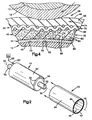
- the blanket 20 has a central axis 40, a pressure area 42 and a supporting sleeve 44.
- the pressure area 42 is elastic and has a cylindrical shape with a gapless outer pressure surface 46.
- the sleeve 44 is quite stiff and has a gapless, cylindrical inner bearing surface 48.
- the sleeve 44 is made of nickel.
- the blanket cylinder 14 is also shown schematically in FIG. 2.
- the blanket cylinder 14 has one Center axis 50 and a pair of stub shafts 52 for storage so that it rotates about axis 50 in printing unit 10.
- the blanket cylinder 14 also has a cylindrical outer surface 54 with a rounded edge 56 at one axial end thereof.
- the blanket cylinder 14 has an outer diameter which is slightly larger than the inner diameter of the sleeve 44 in the blanket 20.
- the blanket cylinder 14, the beveled edge 56 of which slopes radially inward from the outer surface 54, has a diameter at its radially inner end which is is slightly smaller than the inner diameter of the sleeve 44.
- the blanket cylinder 14 also has a number of air flow openings 58 on its outer surface 54.
- air flow openings 58 are arranged in a circumferential row close to the chamfered edge 56 and communicate with an air inlet opening 60 via a number of air passage openings 62 (FIGS. 3, 4) in the blanket cylinder 14.
- the air inlet opening 60 is optionally connected to an air pressure source 64 via an air pressure line 66.
- the rubber blanket 20 can be attached telescopically over the rubber blanket cylinder 14. Since the outer diameter of the blanket cylinder 14 is slightly larger than the inner diameter of the sleeve 44 in the blanket 20, the sleeve 44 inevitably widens in diameter when it is moved in the axial direction towards the cylindrical outer surface 54 and against the beveled edge 56. When the inner surface portion 48 of the sleeve 44 is moved axially over the air flow openings 58 located on the outer surface 54 of the blanket cylinder 14, the air pressure from the source 64 is directed onto the air flow openings 58. Compressed air then flows radially out of the openings 58, strikes the inner surface 48 of the sleeve 44 and expands this further in its diameter.
- the compressed air directed onto the inner surface 48 of the sleeve 44 continuously expands the sleeve 44 while it is being moved axially over the outer surface 54 of the blanket cylinder 14. After the blanket 20 has been brought into its application position on the blanket cylinder 14, the air pressure drops.
- the sleeve 44 in the blanket 20 narrows in diameter and rests elastically against the outer surface 54 of the blanket cylinder 14.
- the blanket 20, whose original inner diameter is less than the outer diameter of the blanket cylinder 14, is thus installed on the blanket cylinder 14 in a superimposed fit .
- the blanket 20 is again removed by stretching the sleeve 44 in diameter under the action of air pressure and axially pushing the blanket 20 away from the blanket cylinder 14 when it is in an expanded condition.
- the nickel material of the sleeve 44 has the optimal elasticity for installing and removing the blanket 20 in the manner described above when it has a conventional air pressure of 61.8 N / cm2 (6.3 kp / cm2; 90 pounds per square inch) ) is subjected.
- the printing area 42 of the rubber blanket 20 consists of layers.
- the print area 42 consists of layers similar to the layers disclosed in U.S. Patent No. 3,700,541 (Shrimpton et al).
- the printing area 42 of the rubber blanket 20 thus consists of a compressible layer 70, a reinforcing layer 72 and a printing layer 74.
- the compressible layer 70 in the pressure area 42 of the blanket 20 is secured to the sleeve 44 by an adhesive bond 80 and comprises a body 82 made of rubber-like material.
- the body 82 made of rubber-like material has microcells 84 evenly distributed therein, which gives the body 82 compressibility.
- the microcells are created by integrating compressible, hollow microspheres 86 into the rubber-like material of the body 82.
- the rubber-like body 82 could also be integrated by integrating a material other than microspheres 86, e.g. B. with pieces from in U.S. Patent 3,887,750 to Duckett et al shown compressible threads can be made compressible.
- the body 82 could be formed using known methods of cavity generation, such as through in the U.S. U.S. Patent 4,025,685 to Haran et al shown blowing and leaching to be compressible.
- the reinforcing layer 72 in the printing area 42 of the rubber blanket 20 consists of a fabric 90 which is bound with a polymer mixture.
- the printing layer 72 is made of a body 96 of rubber-like material and forms the outer printing surface 46 of the blanket 20.
- the printing layer 74 is cylindrical, and the outer printing surface 46 is a continuous, gapless cylindrical surface that extends circumferentially around the blanket 20.
- the printing plate 18 on the plate cylinder 12 moves against the blanket 20 on the blanket cylinder 14 in the gap 28 between the plate cylinder 12 and the blanket cylinder 14
- the blanket 20 is pressed in where the pressure plate 18 presses against this in the nip 28.
- the compressible layer 70 in the rubber blanket 20 is compressed below the pressed-in portions of the printing layer 74 and the reinforcing layer 72.
- the compressible layer 70 allows the pressure layer 74 and the reinforcing layer 72 to be displaced radially inward, so that the pressure surface 46 of the pressure layer 74 on both sides of the nip 28 does not bulge radially outwards.
- the colored printing image transferred from the printing plate 18 to the blanket 20 could be smeared by such a deformation of the printing surface 46, such as this is known from the prior art.
- the plate cylinder 12 rotates clockwise and the blanket cylinder 14 counterclockwise, at the same speed per minute.
- the printing plate 18 is immovably mounted on the plate cylinder 12 and therefore rotates at the same speed as the plate cylinder 12.
- the blanket 20 is not immovably mounted on the blanket cylinder 14. Rather, the blanket 20 attached to the blanket cylinder 14 has a tight fit between the inner surface 48 of the blanket 20 and the outer surface 54 of the blanket cylinder 14.
- the radial strength of the interference fit creates a normal force between the inner surface 48 and the outer surface 54. This results in a frictional force that opposes movement of the inner surface 48 and the outer surface 54 relative to one another.
- the friction force corresponds to the result of the normal force and is the friction factor between these surfaces.
- the inner surface 48 can be moved in sliding contact with the outer surface 54 when a corresponding force is exerted thereon in order to overcome the movement-inhibiting frictional force between the surfaces.
- the pressure plate 18 presses against the rubber blanket 20 in the gap 28.
- the pressure plate 18 thus exerts a force on the rubber blanket 20 in the gap 28.
- the other blanket 34 on the impression cylinder 15 presses in the gap 32 (FIG. 1) in a similar manner against the blanket 20.
- this other blanket 34 in the gap 32 also exerts a force on the blanket 20.
- the frictional force which opposes a movement between the inner surface 48 of the rubber blanket 20 and the outer surface 54 of the rubber blanket cylinder 14, is such that the forces exerted by the plate cylinder 18 and the other rubber blanket 34 on the rubber blanket 20 are sufficient to provide the frictional resistance against a Overcome movement between these surfaces.
- the forces exerted by the printing plate 18 and the other blanket 34 on the blanket 20 are thus large enough to cause the inner surface 48 to be moved in sliding contact with the outer surface 54 during the printing process.
- the blanket 20 thus rotates at a slightly lower speed per minute than the blanket cylinder 14, the plate cylinder 12 and the printing plate 18.
- the sleeve 44 in the blanket 20 has a thickness of 0.127 mm and the inner surface 48 of the sleeve 44 has an inner diameter of 16.626 cm if the blanket 20 is not installed on the blanket cylinder 14.
- the outer surface 54 of the blanket cylinder 14 has a diameter of 16.648 cm.
- the blanket 20 and the blanket cylinder 14 have an initial diametrical overlay of 0.216 mm.
- the blanket 20 When the blanket 20 is installed on the blanket cylinder 14, this initial diametrical superposition, together with the friction factor between the blanket 20 and the blanket cylinder 14, creates a frictional force that resists movement between the surfaces 48 and 54.
- This frictional force is greater than the forces exerted on the blanket 20 in the cylinder gaps 28 and 32, to the extent that during the printing process the blanket 20 extends circumferentially relative to the blanket cylinder 14 between 25 mm and 50 mm per 100,000 revolutions of the Blanket cylinder 14 moves.
- the blanket would move between 25 mm and 50 mm per hour when the printing unit 10 was running at a machine speed of 914 m per minute, and would move about 20.32 cm in total in an 8 hour shift.
- the location on its printing surface 46, to which the inked printed image is transferred is also moved 20.32 cm circumferentially around the printing surface 46 .
- This gradual change in the location on the printing surface 46, whereupon the inked printed image is transferred prevents an accumulation of color on the printing surface 46.
- Such an ink accumulation could form if the inked printing image was repeatedly in the same location on the printing surface throughout the printing process 46 would be transferred.
- the frictional force opposing the movement of the rubber blanket 20 relative to the rubber blanket cylinder 14 can be adjusted and thereby the degree of movement of the rubber blanket 20 relative to the rubber blanket cylinder 14 can be controlled will.
- the frictional force can be adjusted by changing the normal force and by changing the friction factor between the blanket 20 and the blanket cylinder 14.
- the normal force can be changed by changing the initial diametric overlay.
- the friction factor can be changed by changing the structure of surfaces 48 and / or 54, such as polishing, grinding, etc.
- the friction factor can also be changed by using a friction increasing or reducing material between surfaces 48 and 54. For example, as shown schematically in broken lines in FIG. 3, a coating 100 having a predetermined friction factor can be applied to one or both of the surfaces 48 and 54.
Landscapes
- Engineering & Computer Science (AREA)
- Mechanical Engineering (AREA)
- General Engineering & Computer Science (AREA)
- Physics & Mathematics (AREA)
- Fluid Mechanics (AREA)
- Printing Plates And Materials Therefor (AREA)
Claims (9)
- Groupe imprimant offset (10) pour l'impression d'une image imprimante colorée encrée sur une bande de matière en feuille (30) qui présente les caractéristiques suivantes : un cylindre porte-plaque tournant (12) équipé d'un mécanisme (19) pour caler une plaque d'impression (18), sur laquelle est établie une image imprimante encrée ;
un cylindre porte-blanchet tournant (14) ;
un blanchet (20) en forme de manchon, qui est monté télescopiquement sur ledit cylindre porte-blanchet (14) ;
des bâtis (16) pour le tourillonnement dudit cylindre porte-plaque (12) et dudit cylindre porte-blanchet (14) dans des positions dans lesquelles une plaque d'impression (18) montée sur ledit cylindre porte-plaque (12) reporte l'image imprimante encrée sur ledit blanchet (20) en forme de manchon, dans la fente (28) formée entre lesdits cylindres (12, 14) lorsque lesdits cylindres (12, 14) sont mis en rotation ;
un moteur (26) servant à faire tourner ledit cylindre porte-plaque (12) et ledit cylindre porte-blanchet (14) pour effectuer le report de l'image imprimante encrée sur ledit blanchet en forme de manchon ; et
ledit blanchet en forme de manchon (20) est monté sur le cylindre porte-blanchet (14) de telle manière que ce blanchet tourne par rapport audit cylindre porte-blanchet lorsque lesdits cylindres (12, 14) sont entraînés par ledit moteur (26). - Groupe imprimant offset (10) selon la revendication 1,
caractérisé
en ce que ledit cylindre porte-blanchet (14) a une première surface de montage (54) dirigée radialement vers l'extérieur, le blanchet (20) en forme de manchon a une deuxième surface de montage (48) dirigée radialement vers l'intérieur, la deuxième surface de montage (48) est en contact de friction avec ladite première surface de montage (54) et ladite deuxième surface de montage (48) peut se déplacer circonférentiellement par rapport à ladite surface de montage (54), en contact de translation avec celle-ci, lorsque lesdits cylindres (12, 14) sont entraînés par ledit moteur (26). - Groupe imprimant offset (10) selon la revendication 2,
caractérisé
en ce que ledit blanchet en forme de manchon (20) comprend une région d'impression cylindrique (42) et un manchon cylindrique (44), ladite région d'impression (42) présente une surface d'impression (46) cylindrique extérieure, continue dépourvue de fente, et ledit manchon (44) porte ladite région d'impression (42) mise à une forme cylindrique, et présente une surface interne (48) cylindrique, continue, dépourvue de fente, qui est ladite deuxième surface de montage. - Groupe imprimant offset (10) selon la revendication 1,
caractérisé
en ce que ledit cylindre porte-plaque (12) est tourillonné dans lesdits bâtis (16) dans une position dans laquelle une plaque d'impression (18) montée sur ledit cylindre porte-plaque (12) exerce une force sur ledit blanchet (20) en forme de manchon dans ladite fente (28) entre cylindres lorsque lesdits cylindres (12, 14) sont entraînés en rotation par ledit moteur (26) de telle manière que le blanchet en forme de manchon (20) monté sur ledit cylindre porte-blanchet (14) tourne par rapport audit cylindre porte-blanchet (14) sous l'influence de ladite force exercée sur ladite fente (28) entre cylindres. - Groupe imprimant offset (10) selon la revendication 4,
qui comprend en outre :
un cylindre d'impression tournant (15) qui est tourillonné par lesdits bâtis (16) dans une position dans laquelle une surface formée sur ledit cylindre d'impression (15) exerce une force sur ledit blanchet en forme de manchon (20) dans la fente (32) entre ledit cylindre d'impression (15) et ledit cylindre porte-blanchet (14), de sorte que ledit blanchet en forme de manchon (20) tourne par rapport audit cylindre porte-blanchet (14) sous l'influence desdites forces exercées dans lesdites fentes (28, 32) entre cylindres. - Groupe imprimant offset (10) selon la revendication 5,
caractérisé
en ce que ledit moteur (26) fait tourner ledit cylindre porte-blanchet (14) autour de son axe dans un premier sens et en ce que ledit blanchet (20) en forme de manchon est monté sur ledit cylindre porte-blanchet (14) de telle manière que ce blanchet tourne par rapport audit cylindre porte-blanchet (14) dans un deuxième sens inverse dudit premier sens sous l'influence desdites forces exercées dans lesdites fentes (28, 32) entre cylindres. - Procédé d'impression avec un groupe imprimant offset (10), qui possède les caractéristiques suivantes :
un cylindre porte-plaque tournant (12) équipé d'une plaque d'impression (18) sur laquelle est formée une image imprimante encrée, un cylindre porte-blanchet tournant (14), des bâtis (16) pour le tourillonnement du cylindre porte-plaque (12) et du cylindre porte-blanchet (14) dans des positions dans lesquelles, dans la fente (28) entre les cylindres (12, 14), la plaque d'impression (18) portée par le cylindre porte-plaque (12) reporte l'image imprimante encrée sur un blanchet (20) qui se trouve sur le cylindre porte-blanchet (14) lorsque le cylindre (12, 14) est entrainé en rotation, et un moteur (26) servant à entraîner le cylindre porte-plaque (12) et le cylindre porte-blanchet (14) pour assurer le report de l'image imprimante encrée sur le cylindre porte-blanchet (20), le procédé selon l'invention comprenant les phases suivantes :
le montage du blanchet en forme de manchon (20) sur le cylindre porte-blanchet (14) par emmanchement télescopique du blanchet (20) en forme de manchon sur le cylindre porte-blanchet (14) ; et
l'entraînement en rotation du blanchet (20) en forme de manchon par rapport au cylindre porte-blanchet (14) lorsque le cylindre porte-plaque (12) et le cylindre porte-blanchet (14) sont entraînés par le moteur (26) pour assurer le report de l'image imprimante encrée sur le blanchet (20) en forme de manchon. - Procédé selon la revendication 7,
caractérisé
en ce que ledit cylindre porte-plaque (12) et ledit cylindre porte-blanchet (14) sont entraînés par ledit moteur (26) au même nombre de tours par minute, et en ce que ledit blanchet (20) en forme de manchon est entraîné en rotation par rapport audit cylindre porte-blanchet (14) lorsque ledit cylindre porte-plaque (12) et ledit cylindre porte-blanchet (14) sont entraînés audit nombre de tours identique pour les deux. - Procédé selon la revendication 7,
caractérisé
en ce que ledit blanchet (20) en forme de manchon est monté sur ledit cylindre porte-blanchet (14) avec une force de frottement qui résiste à un mouvement périphérique dudit blanchet (20) en forme de manchon en contact de translation avec ledit cylindre porte-blanchet (14) et en ce que ledit blanchet en forme de manchon (20) se déplace circonférentiellement en contact de translation avec ledit cylindre porte-blanchet (14) sous l'influence de la pression exercée sur sa surface extérieure.
Applications Claiming Priority (2)
| Application Number | Priority Date | Filing Date | Title |
|---|---|---|---|
| US07/909,729 US5245923A (en) | 1992-07-07 | 1992-07-07 | Printing press with movable printing blanket |
| US909729 | 1992-07-07 |
Publications (2)
| Publication Number | Publication Date |
|---|---|
| EP0581019A1 EP0581019A1 (fr) | 1994-02-02 |
| EP0581019B1 true EP0581019B1 (fr) | 1996-05-22 |
Family
ID=25427731
Family Applications (1)
| Application Number | Title | Priority Date | Filing Date |
|---|---|---|---|
| EP93110105A Expired - Lifetime EP0581019B1 (fr) | 1992-07-07 | 1993-06-24 | Blanchet pour machine à imprimer en offset |
Country Status (3)
| Country | Link |
|---|---|
| US (1) | US5245923A (fr) |
| EP (1) | EP0581019B1 (fr) |
| DE (2) | DE59302665D1 (fr) |
Cited By (6)
| Publication number | Priority date | Publication date | Assignee | Title |
|---|---|---|---|---|
| DE10006722A1 (de) * | 2000-02-15 | 2001-08-16 | Roland Man Druckmasch | Offsetdruckmaschine mit einer Registersteuerung und Verfahren zum Betreiben derselben |
| US7516698B2 (en) | 2005-03-30 | 2009-04-14 | Goss International Americasn, Inc. | Web offset printing press with autoplating |
| US7775159B2 (en) | 2005-03-30 | 2010-08-17 | Goss International Americas, Inc. | Cantilevered blanket cylinder lifting mechanism |
| US7819057B2 (en) | 2005-03-30 | 2010-10-26 | Goss International Americas, Inc. | Print unit having blanket cylinder throw-off bearer surfaces |
| US7849796B2 (en) | 2005-03-30 | 2010-12-14 | Goss International Americas, Inc | Web offset printing press with articulated tucker |
| US8037818B2 (en) | 2005-04-11 | 2011-10-18 | Goss International Americas, Inc. | Print unit with single motor drive permitting autoplating |
Families Citing this family (22)
| Publication number | Priority date | Publication date | Assignee | Title |
|---|---|---|---|---|
| US5601020A (en) * | 1993-01-22 | 1997-02-11 | Heidelberger Druckmaschinen Ag | Apparatus for reducing procession of a tubular printing sleeve |
| DE4341262C2 (de) * | 1993-01-22 | 1999-04-08 | Heidelberger Druckmasch Ag | Vorrichtung für die Reduzierung von Materialausbuchtungen auf einer rohrförmigen Druckhülse |
| DE4340915A1 (de) * | 1993-02-23 | 1994-08-25 | Heidelberger Druckmasch Ag | Auswechselbare Andrückhülse |
| DE9305806U1 (de) * | 1993-04-19 | 1993-06-09 | Hoechst Ag, 6230 Frankfurt | Druckwalze mit einer Hülse aus thermisch gewickelten faserverstärkten Thermoplasten und einer plasmagespritzten Kupfer- oder Kupferlegierungsbeschichtung |
| DE4415711A1 (de) * | 1994-05-04 | 1995-11-09 | Roland Man Druckmasch | Druckeinheit für Gummi-Gummi-Druck |
| US6119597A (en) * | 1994-06-14 | 2000-09-19 | Howard W. DeMoore | Method and apparatus for handling printed sheet material |
| US5779370A (en) * | 1996-02-20 | 1998-07-14 | Premark Feg L.L.C. | Apparatus for printing labels and a self-releasing print roller therefor |
| DE59706477D1 (de) * | 1996-07-16 | 2002-04-04 | Roland Man Druckmasch | Gummizylinderhülse, insbesondere für Offset-Rollenrotationsdruckmaschinen |
| US5795088A (en) * | 1996-11-08 | 1998-08-18 | Eastman Kodak Company | Platen roller sleeved with heat shrinking tube for improved color registration in a platen-drive resistive thermal printer |
| USRE38468E1 (en) | 1996-12-04 | 2004-03-23 | Day International, Inc. | Replaceable sleeve |
| US5860360A (en) * | 1996-12-04 | 1999-01-19 | Day International, Inc. | Replaceable printing sleeve |
| US5842412A (en) * | 1997-03-07 | 1998-12-01 | Bba Nonwovens Simpsonville, Inc. | Anti-marking covering for printing press transfer cylinder |
| JPH1177971A (ja) * | 1997-09-05 | 1999-03-23 | Shinano Kenshi Co Ltd | ブランケット胴及び該ブランケット胴を備えたオフセット印刷装置 |
| EP1334825B1 (fr) * | 1999-12-02 | 2011-06-01 | Koenig & Bauer Aktiengesellschaft | Groupe d'impression d'une machine d'impression |
| US6257140B1 (en) * | 1999-12-27 | 2001-07-10 | Heidelberger Druckmaschinen Ag | Continuous process gapless tubular lithographic printing blanket |
| US6401613B1 (en) * | 2000-05-23 | 2002-06-11 | Xymid, Llc | Printing cylinder sleeve assembly |
| IT1318961B1 (it) | 2000-10-03 | 2003-09-19 | Erminio Rossini S P A Ora Ross | Manica perfezionata per cilindro sussidiario di una macchina da stampaindiretta o "offset". |
| US6640711B2 (en) * | 2002-01-15 | 2003-11-04 | Michael A. Smoot | Bridge mandrel for use as a repeat builder in a printing machine |
| ITMI20071405A1 (it) * | 2007-07-13 | 2009-01-14 | Acobas Roberto Levi | Rivestimento per cilindro portacaucciu' di una macchina di stampa cilindro che incorpora tale rivestimento macchina da stampa che incorpora tale cilindro e procedimento per la presisposizione di un cilindro portacaucciu' in una macchina da stampa |
| US20090193991A1 (en) * | 2008-02-04 | 2009-08-06 | Felice Rossini | Blanket sleeve and cylinder and method of making same |
| US20100307356A1 (en) * | 2008-02-04 | 2010-12-09 | Felice Rossini | Bridged sleeve/cylinder and method of making same for web offset printing machines |
| CN105644135B (zh) * | 2016-02-02 | 2018-01-12 | 京东方科技集团股份有限公司 | 转印设备和涂布机 |
Family Cites Families (15)
| Publication number | Priority date | Publication date | Assignee | Title |
|---|---|---|---|---|
| US3146709A (en) * | 1962-04-09 | 1964-09-01 | West Essex Printing Plate Inc | Method and apparatus for mounting printing sleeves |
| US3700541A (en) * | 1970-04-11 | 1972-10-24 | Dunlop Holdings Ltd | Printers' blankets |
| US3881045A (en) * | 1973-07-24 | 1975-04-29 | Du Pont | Offset printing blanket |
| US4025685A (en) * | 1974-09-06 | 1977-05-24 | Dayco Corporation | Compressible printing blanket and method of manufacture |
| US4174244A (en) * | 1976-05-28 | 1979-11-13 | Industrial Electronic Rubber Company | Method of making a printing blanket |
| DE2742002A1 (de) * | 1977-09-17 | 1979-03-29 | Ludwig Zboron | Tiefdruckzylinder |
| US4303721A (en) * | 1979-07-20 | 1981-12-01 | W. R. Grace & Co. | Closed cell foam printing blanket |
| DE3139494C2 (de) * | 1981-09-30 | 1983-11-10 | Herlitz Ag, 1000 Berlin | Walze |
| DE3543704A1 (de) * | 1985-12-11 | 1987-06-19 | Md Papierfabrik Pasing Nicolau | Vorrichtung und verfahren zum bedrucken einer bahn |
| DE3618941A1 (de) * | 1986-06-05 | 1987-12-10 | Phoenix Ag | Haftpasten |
| US4953461A (en) * | 1988-05-20 | 1990-09-04 | Harris Graphics Corporation | System for continuously rotating plate a blanket cylinders at relatively different surface speeds |
| US4932324A (en) * | 1988-06-06 | 1990-06-12 | Day International Corporation | Mounting device for adhesive-backed blankets |
| US4903597A (en) * | 1988-10-24 | 1990-02-27 | Lavalley Industries, Inc. | Printing sleeves and methods for mounting and dismounting |
| ES2048915T5 (es) * | 1989-10-05 | 1999-11-01 | Heidelberger Druckmasch Ag | Maquina de impresion offset. |
| CA2068629C (fr) * | 1991-05-14 | 1996-05-07 | James B. Vrotacoe | Blanchet d'imprimerie tubulaire sans passage |
-
1992
- 1992-07-07 US US07/909,729 patent/US5245923A/en not_active Expired - Lifetime
-
1993
- 1993-06-24 EP EP93110105A patent/EP0581019B1/fr not_active Expired - Lifetime
- 1993-06-24 DE DE59302665T patent/DE59302665D1/de not_active Expired - Fee Related
- 1993-06-24 DE DE4320923A patent/DE4320923B4/de not_active Expired - Fee Related
Cited By (8)
| Publication number | Priority date | Publication date | Assignee | Title |
|---|---|---|---|---|
| DE10006722A1 (de) * | 2000-02-15 | 2001-08-16 | Roland Man Druckmasch | Offsetdruckmaschine mit einer Registersteuerung und Verfahren zum Betreiben derselben |
| DE10006722B4 (de) * | 2000-02-15 | 2010-08-19 | Manroland Ag | Verfahren zum Betreiben einer Offsetdruckmaschine |
| US7516698B2 (en) | 2005-03-30 | 2009-04-14 | Goss International Americasn, Inc. | Web offset printing press with autoplating |
| US7775159B2 (en) | 2005-03-30 | 2010-08-17 | Goss International Americas, Inc. | Cantilevered blanket cylinder lifting mechanism |
| US7819057B2 (en) | 2005-03-30 | 2010-10-26 | Goss International Americas, Inc. | Print unit having blanket cylinder throw-off bearer surfaces |
| US7849796B2 (en) | 2005-03-30 | 2010-12-14 | Goss International Americas, Inc | Web offset printing press with articulated tucker |
| US8250976B2 (en) | 2005-03-30 | 2012-08-28 | Goss International Americas, Inc. | Cantilevered blanket cylinder lifting mechanism |
| US8037818B2 (en) | 2005-04-11 | 2011-10-18 | Goss International Americas, Inc. | Print unit with single motor drive permitting autoplating |
Also Published As
| Publication number | Publication date |
|---|---|
| US5245923A (en) | 1993-09-21 |
| DE59302665D1 (de) | 1996-06-27 |
| DE4320923A1 (de) | 1994-01-13 |
| EP0581019A1 (fr) | 1994-02-02 |
| DE4320923B4 (de) | 2004-08-26 |
Similar Documents
| Publication | Publication Date | Title |
|---|---|---|
| EP0581019B1 (fr) | Blanchet pour machine à imprimer en offset | |
| EP0581018B1 (fr) | Blanchet avec amortissement du bruit | |
| EP0549936B1 (fr) | Cylindre de transfert avec manchon échangeable, supporté entre deux parois latérales d'un élément d'impression | |
| EP0421145B2 (fr) | Machine offset | |
| EP0894623B1 (fr) | Groupe imprimant pour une machine rotative | |
| DE19646135A1 (de) | Druckwerk mit axial entfernbaren Druckhülsen | |
| EP0946370A1 (fr) | Cylindre pour presse rotative | |
| DE102008046792A1 (de) | Druckmaschine mit Schmitzringen | |
| EP1338418B1 (fr) | Machine à imprimer avec un dispositif de nettoyage du cliché | |
| EP1476305A1 (fr) | Manchon a ensemble multicouches pour une machine a imprimer et procede de production associe | |
| DE10103233A1 (de) | Vorrichtung zum Antreiben von Druckwerkszylindern | |
| DE3344777C1 (de) | Feuchtmitteldosiervorrichtung für das Feuchtwerk einer Druckmaschine | |
| EP1291176B1 (fr) | Machine à imprimer et procédé d'opération d'un dispositif d'encrage | |
| EP0563534B1 (fr) | Dispositif pour déplacer un cylindre de plaque relativement à un cylindre de blanchet | |
| CH678710A5 (fr) | ||
| DE69508346T2 (de) | Farbzuführvorrichtung für eine Schablonendruckmaschine | |
| EP0518084A1 (fr) | Presse d'impression offset avec formation d'émulsion commandée | |
| DE3515610C1 (de) | Andrueckrolle fuer ein Etikettiergeraet | |
| DE3213540C2 (de) | Rotations-Druckmaschine für den Druck mit hoch viskosen Farben | |
| EP0353652B1 (fr) | Dispositif supplémentaire pour montage sur une machine d'impression offset | |
| DE69601058T2 (de) | Schablonendruckmaschine mit Vorrichtung zum Verhindern von Farblecken | |
| DE10011429A1 (de) | Druckmaschine mit einer Reinigungseinrichtung zur Reinigung zweier Druckmaschinenzylinder | |
| EP1037746B1 (fr) | Rouleau de guidage d'une feuille continue | |
| EP2868471B1 (fr) | Imprimé d'une machine offset rotative | |
| DE1194873B (de) | Farbwerk fuer Rotationsdruckmaschinen |
Legal Events
| Date | Code | Title | Description |
|---|---|---|---|
| PUAI | Public reference made under article 153(3) epc to a published international application that has entered the european phase |
Free format text: ORIGINAL CODE: 0009012 |
|
| 17P | Request for examination filed |
Effective date: 19930624 |
|
| AK | Designated contracting states |
Kind code of ref document: A1 Designated state(s): CH DE FR GB LI SE |
|
| GBC | Gb: translation of claims filed (gb section 78(7)/1977) | ||
| 17Q | First examination report despatched |
Effective date: 19950914 |
|
| GRAH | Despatch of communication of intention to grant a patent |
Free format text: ORIGINAL CODE: EPIDOS IGRA |
|
| GRAA | (expected) grant |
Free format text: ORIGINAL CODE: 0009210 |
|
| AK | Designated contracting states |
Kind code of ref document: B1 Designated state(s): CH DE FR GB LI SE |
|
| REF | Corresponds to: |
Ref document number: 59302665 Country of ref document: DE Date of ref document: 19960627 |
|
| REG | Reference to a national code |
Ref country code: CH Ref legal event code: NV Representative=s name: KIRKER & CIE SA |
|
| GBT | Gb: translation of ep patent filed (gb section 77(6)(a)/1977) |
Effective date: 19960806 |
|
| ET | Fr: translation filed | ||
| PLBE | No opposition filed within time limit |
Free format text: ORIGINAL CODE: 0009261 |
|
| STAA | Information on the status of an ep patent application or granted ep patent |
Free format text: STATUS: NO OPPOSITION FILED WITHIN TIME LIMIT |
|
| 26N | No opposition filed | ||
| PGFP | Annual fee paid to national office [announced via postgrant information from national office to epo] |
Ref country code: SE Payment date: 19970624 Year of fee payment: 5 |
|
| PGFP | Annual fee paid to national office [announced via postgrant information from national office to epo] |
Ref country code: CH Payment date: 19970718 Year of fee payment: 5 |
|
| PG25 | Lapsed in a contracting state [announced via postgrant information from national office to epo] |
Ref country code: SE Free format text: LAPSE BECAUSE OF NON-PAYMENT OF DUE FEES Effective date: 19980625 |
|
| PG25 | Lapsed in a contracting state [announced via postgrant information from national office to epo] |
Ref country code: LI Free format text: LAPSE BECAUSE OF NON-PAYMENT OF DUE FEES Effective date: 19980630 Ref country code: CH Free format text: LAPSE BECAUSE OF NON-PAYMENT OF DUE FEES Effective date: 19980630 |
|
| REG | Reference to a national code |
Ref country code: CH Ref legal event code: PL |
|
| EUG | Se: european patent has lapsed |
Ref document number: 93110105.9 |
|
| REG | Reference to a national code |
Ref country code: GB Ref legal event code: IF02 |
|
| REG | Reference to a national code |
Ref country code: GB Ref legal event code: 732E |
|
| REG | Reference to a national code |
Ref country code: FR Ref legal event code: TP |
|
| PGFP | Annual fee paid to national office [announced via postgrant information from national office to epo] |
Ref country code: FR Payment date: 20090617 Year of fee payment: 17 |
|
| PGFP | Annual fee paid to national office [announced via postgrant information from national office to epo] |
Ref country code: GB Payment date: 20090625 Year of fee payment: 17 Ref country code: DE Payment date: 20090629 Year of fee payment: 17 |
|
| GBPC | Gb: european patent ceased through non-payment of renewal fee |
Effective date: 20100624 |
|
| REG | Reference to a national code |
Ref country code: FR Ref legal event code: ST Effective date: 20110228 |
|
| PG25 | Lapsed in a contracting state [announced via postgrant information from national office to epo] |
Ref country code: DE Free format text: LAPSE BECAUSE OF NON-PAYMENT OF DUE FEES Effective date: 20110101 |
|
| PG25 | Lapsed in a contracting state [announced via postgrant information from national office to epo] |
Ref country code: FR Free format text: LAPSE BECAUSE OF NON-PAYMENT OF DUE FEES Effective date: 20100630 |
|
| PG25 | Lapsed in a contracting state [announced via postgrant information from national office to epo] |
Ref country code: GB Free format text: LAPSE BECAUSE OF NON-PAYMENT OF DUE FEES Effective date: 20100624 |