EP0581041A2 - Orthopädische Vorrichtung - Google Patents
Orthopädische Vorrichtung Download PDFInfo
- Publication number
- EP0581041A2 EP0581041A2 EP93110518A EP93110518A EP0581041A2 EP 0581041 A2 EP0581041 A2 EP 0581041A2 EP 93110518 A EP93110518 A EP 93110518A EP 93110518 A EP93110518 A EP 93110518A EP 0581041 A2 EP0581041 A2 EP 0581041A2
- Authority
- EP
- European Patent Office
- Prior art keywords
- caliper
- user
- orthopaedic
- upper portion
- thigh
- Prior art date
- Legal status (The legal status is an assumption and is not a legal conclusion. Google has not performed a legal analysis and makes no representation as to the accuracy of the status listed.)
- Granted
Links
Images


Classifications
-
- A—HUMAN NECESSITIES
- A61—MEDICAL OR VETERINARY SCIENCE; HYGIENE
- A61F—FILTERS IMPLANTABLE INTO BLOOD VESSELS; PROSTHESES; DEVICES PROVIDING PATENCY TO, OR PREVENTING COLLAPSING OF, TUBULAR STRUCTURES OF THE BODY, e.g. STENTS; ORTHOPAEDIC, NURSING OR CONTRACEPTIVE DEVICES; FOMENTATION; TREATMENT OR PROTECTION OF EYES OR EARS; BANDAGES, DRESSINGS OR ABSORBENT PADS; FIRST-AID KITS
- A61F5/00—Orthopaedic methods or devices for non-surgical treatment of bones or joints; Nursing devices ; Anti-rape devices
- A61F5/01—Orthopaedic devices, e.g. long-term immobilising or pressure directing devices for treating broken or deformed bones such as splints, casts or braces
- A61F5/0102—Orthopaedic devices, e.g. long-term immobilising or pressure directing devices for treating broken or deformed bones such as splints, casts or braces specially adapted for correcting deformities of the limbs or for supporting them; Ortheses, e.g. with articulations
Definitions
- THIS INVENTION relates to an orthopaedic device, more specifically to an orthopaedic device suitable to form part of an orthopaedic caliper. It relates further to an orthopaedic caliper and also to conversion of an orthopaedic caliper.
- the Applicant has identified a problem in conventional orthopaedic calipers which is symptomized by the "paraplegic gait” or posture taken up by paraplegics (and others) when standing with the aid of calipers.
- Such posture is typified by hyperextension (pushing forward) of the hips, backward pelvic tilt and the resultant lying backwards of the torso.
- the Applicant believes that the underlying reason for such a posture, is that a conventional caliper, even though it may purport to be non-ischial weight bearing, is nevertheless in practice at least partially weight bearing on the ischial tuberosity and/or on the soft thigh and buttock tissue of the user in that such tissue "seats" on the upper edge of the caliper. This problem is described herein below with reference to Figures 1 to 4 of the drawings.
- an orthopaedic device which is suitable to form part of an orthopaedic caliper and which comprises a lower portion which is stiff and to which depending components of said orthopaedic caliper will be located in use, the lower portion having an abutment surface positioned to abut the thigh of a user; and an upper portion which is attached to or attachable to the lower portion to extend upwardly from the lower portion in use and which is in the form of a moulding, the upper portion having a shape which is concave and which is generally complemental to an upper rear portion of the thigh and a lower portion of a buttock of the user when standing, the upper portion being of a material which is stretch resistant and which is deformable so as to conform to the shape of the upper portion of the thigh and lower buttock
- the lower portion may be in the form of a collar receivable around the thigh of a user. Instead, preferably it may be part annular only including a tying element of soft material. It may be in the form of a moulding of polypropylene material or other similar material. Instead, it may be in the form of a band, e.g. of steel or other metal, but this is not preferred.
- the upper section may be of synthetic plastics or other mouldable material. It may be of thin polypropylene material or other, similar, material having the required characteristics. It may be moulded into the lower portion. Instead, it may be attached to the lower portion, e.g. adhesively.
- the invention extends to an orthopaedic caliper having, toward an upper end thereof, body attachment means in the form of a new orthopaedic device in accordance with this invention as herein described.
- the invention extends further to a method of converting a conventional orthopaedic caliper into an orthopaedic caliper in accordance with this invention, the method including replacing conventional body attachment means of the conventional caliper with a new orthopaedic device in accordance with this invention and as herein described.
- the invention accordingly extends to an orthopaedic caliper converted in accordance with this invention.
- a prior art orthopaedic caliper is shown, indicated by reference numeral 10. It is of the (supposedly) non weight bearing kind. It is shown in use in association with the left leg 12 of a user. A left hip bone 14 of the user is shown in dotted, including the ischial tuberosity 16 at the lower end of the hip bone 14.
- the forces in play to support the person 22 are generally shown by arrows in Figure 3 and they are redrawn in the form of a force diagram in Figure 4.
- the body weight 28 of the person 22 operates through the centre of gravity of the person i.e. through a point at a lower end of the torso above the hips, and works vertically downwardly.
- the main force operating to counteract the body weight 28 is partially exerted by the caliper 10 on the ischial tuberosity and/or soft tissue of the thigh and hip and is partially carried by the leg bones of the user. Said main force is indicated by reference numeral 30.
- a third force namely a tension force 32
- the stabilizing force 32 is accomplished by tension in ligaments, muscle and tissues along the front of the hips/thighs of the person 22.
- the prior art caliper and the way it supports the human body have many disadvantages, symptomized by the posture of the user as shown in Figure 3, which posture is also known as "paraplegic gait".
- Those disadvantages are merely briefly mentioned as they are well known in the field of the invention.
- the posture of the person is uncomfortable and leads to fatigue and other undesirable side effects like unnatural muscle position, excessive compensating dorsal kyphosis, undesirable stress on other parts of the anatomy like the lower back, an inefficient walking aid, poor leg extension requiring extensive strapping, and the like.
- To enable the person to use the caliper for support it is necessary to tie the body attachment means tightly around the person's legs, thus squeezing or pressuring the soft tissue.
- the person's leg including the leg bones are to a large extent inactive whereas they would have benefited by being as active as possible.
- the backward pelvic tilt that occurs when using a conventional caliper results from a small increase in knee flexion when the hip is hyperextended during standing.
- This knee flexion occurs since the relatively short lever arm of the caliper (above knee joint) exerts localized forces on the posterior aspect of the thigh, depressing the soft tissue. Tightening the caliper thigh straps to depress the soft tissue prior to standing reduces this knee flexion, but increases the circumferential pressure on the leg. This circumferential pressure is uncomfortable and physiologically undesirable.
- the caliper may become weight bearing if the caliper cuff/band is fixed too high (to increase the lever arm above the knee) and is forced by the thigh strap below the ischium.
- the Figure 2 caliper is intended for use when the leg bones cannot be loaded. It operates entirely differently to a caliper of this invention.
- a caliper of this invention is intended to load the leg bones, and is thus not intended to replace a caliper of the ischial weight bearing kind.
- a caliper in accordance with this invention is generally indicated by reference numeral 40. It comprises an orthopaedic device 42 towards an upper end thereof which orthopaedic device is in accordance with this invention.
- the caliper 40 further comprises a depending portion 44 which can be conventional.
- the orthopaedic device 42 is mounted on elongate supports 46 extending upwardly from the depending portion 44.
- the orthopaedic device 42 has a lower portion in the form of a collar 48 which is receivable around the thigh of a user. For that purpose, it is conveniently discontinuous to allow easy access for the thigh and can then be tied to the person's thigh by means of a flap 48.2 and complemental VELCHRO strips 48.1 and 48.3. It is emphasised that the lower portion 48 is merely snugly located on the person's thigh ie it is not tightly strapped to a thigh like in conventional calipers.
- the orthopaedic device 42 further comprises an upper portion generally indicated by reference numeral 50.
- the upper portion 50 is in the form of a moulding of synthetic plastics material like thin polypropylene and is generally concave in the form of a composite cradle cradling the rear upper portion of the person's thigh and a portion of his buttock.
- the upper portion may conveniently be moulded into the lower portion 38. Instead, it may be located within the lower portion e.g. adhesively.
- the upper portion 50 is moulded to have a low profile, as indicated by reference numeral 50.1, along its medial side in use. It has a relatively high profile, as indicated by reference numeral 50.2, along its outside in use, but this is not a requirement. Along the rear, it may be moulded to have a slight bulge, as indicated by reference numeral 50.3, to follow the buttock contour of the user.
- the material of the upper portion is soft or pliable but is nevertheless stretch resistant. However, in the concave or cradle-like form it assumes and when stabilized against the lower portion 48, it is stiff enough to be resistant against bending and it can exert a force on the thigh and buttock of the user which force has a predominantly horizontal forward component.
- the lower portion 48 is stabilised on the thigh of the user such that it can exert horizontal force components (i.e. generally perpendicular to adjacent body surfaces of the user) and that it is not tight to the extent that it can exert large vertical force components (i.e. generally along adjacent body surfaces of the user). Thus, it does not squeeze or pressurise the soft tissue of the thigh unduly.
- the upper portion 50 as described above, can exert horizontally forward force components on the body of the user but does not promote flexion of the hips. It thus does not allow large vertical force components to be applied to the body.
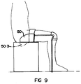
- a user has a posture which is akin to that of a normal person and which is substantially different to the "paraplegic gait" illustrated in Figure 3.
- the forces in play include a vertically downward force indicated by reference numeral 128 representing the body weight of the user and acting vertically downwardly through the person's centre of gravity. Furthermore, and this is very important in the context of the invention, the body weight of the person is largely balanced by a force in the leg bones of the person as indicated by reference numeral 130 which force acts through the hip joint of the person in a manner similar to that of a normal person.
- the forces 128 and 130 are illustrated in Figure 8 and it can also be seen that only a relatively small stabilizing force, operating in a direction which is substantially horizontally forward, is required to close the force diagram.
- the stabilising force is indicated by reference numeral 132 and is in practice exerted by the upper portion 50 onto the rear of the thigh and the buttock of a user. It is important to appreciate, first, that the magnitude of the force 132 is small, and, second, that the direction of the force is such that its component perpendicular to the body surface of the user is predominant.
- the mechanical action of the orthopaedic device 42 is to direct the posterior forces, which are conventionally exerted on the thigh (femur), to the buttock (back of the ischium). This position is mechanically superior as it increases the lever arm of the caliper reducing the magnitude of the proximal posterior forces. These forces are distributed on the buttock (ie primarily to the back of the ischium) and promote rotation of the pelvis and thus hip extension.
- the invention have a large number of advantages, inter alia that the unnatural and undesirable "paraplegic gait" is to a large extent eliminated and the stresses on the body of a person are much more similar to those of a normal person.
- the leg bones of a user are used to a large extent to carry the person's weight thus activating at least the leg bones and the joint of the user, which is desirable.
- the caliper is used primarily to stabilize the user's leg and not to carry the weight, it is stressed to a much lower degree.
- the caliper can be made lighter than in conventional calipers, which greatly adds to the comfort of the user.
- the caliper is no longer weight bearing to a large extent, attachment to the body of the user is mostly for location and the forces exerted are small and are directed such that force components perpendicular to the body surfaces of the user are predominant, thus allowing snug fitting rather than tight fitting which, to a large extent, reduces or even illuminates pressuring and squeezing of soft tissue.
- the shape, construction and material of the upper portion of the orthopaedic device allows the bulging shape thereof to fold or collapse when a user is seated, thus preventing pressure points on bony prominances (the ischial tuberosity) and preventing undue pressure underneath the thigh.
- the upper portion conforms to the shape of the body of the user inasmuch as it will be less prominent and will present a smoother, more natural image.
Landscapes
- Health & Medical Sciences (AREA)
- Nursing (AREA)
- Orthopedic Medicine & Surgery (AREA)
- Engineering & Computer Science (AREA)
- Biomedical Technology (AREA)
- Heart & Thoracic Surgery (AREA)
- Vascular Medicine (AREA)
- Life Sciences & Earth Sciences (AREA)
- Animal Behavior & Ethology (AREA)
- General Health & Medical Sciences (AREA)
- Public Health (AREA)
- Veterinary Medicine (AREA)
- Orthopedics, Nursing, And Contraception (AREA)
Applications Claiming Priority (2)
| Application Number | Priority Date | Filing Date | Title |
|---|---|---|---|
| ZA924894 | 1992-07-01 | ||
| ZA924894 | 1992-07-01 |
Publications (3)
| Publication Number | Publication Date |
|---|---|
| EP0581041A2 true EP0581041A2 (de) | 1994-02-02 |
| EP0581041A3 EP0581041A3 (en) | 1994-06-08 |
| EP0581041B1 EP0581041B1 (de) | 1997-05-21 |
Family
ID=25581843
Family Applications (1)
| Application Number | Title | Priority Date | Filing Date |
|---|---|---|---|
| EP93110518A Expired - Lifetime EP0581041B1 (de) | 1992-07-01 | 1993-07-01 | Orthopädische Vorrichtung |
Country Status (4)
| Country | Link |
|---|---|
| US (1) | US5387184A (de) |
| EP (1) | EP0581041B1 (de) |
| DE (1) | DE69310826T2 (de) |
| ZA (1) | ZA936020B (de) |
Cited By (1)
| Publication number | Priority date | Publication date | Assignee | Title |
|---|---|---|---|---|
| US6893411B1 (en) * | 2003-03-21 | 2005-05-17 | Deroyal Industries, Inc. | Thigh cuff extension |
Families Citing this family (3)
| Publication number | Priority date | Publication date | Assignee | Title |
|---|---|---|---|---|
| US5993404A (en) * | 1998-06-16 | 1999-11-30 | Mc Niel; Frank T. | Walking brace |
| US8679046B2 (en) | 2009-06-29 | 2014-03-25 | Fraunhofer-Gesellschaft Zur Forderung Der Angewandten Forschung E.V. | Supporting device |
| WO2014067015A1 (en) * | 2012-11-01 | 2014-05-08 | British Columbia Institute Of Technology | Mobility system including an exoskeleton assembly releasably supported on a wheeled base |
Family Cites Families (9)
| Publication number | Priority date | Publication date | Assignee | Title |
|---|---|---|---|---|
| US1490265A (en) * | 1922-01-13 | 1924-04-15 | Robert D Glasgow | Orthopedic appliance and device |
| US2516253A (en) * | 1947-02-14 | 1950-07-25 | Adrian J Pieterick | Orthopedic brace |
| US2573866A (en) * | 1948-05-14 | 1951-11-06 | Myron W Nusbaum | Leg brace |
| US2827897A (en) * | 1956-05-14 | 1958-03-25 | Zygmunt A Pawlowski | Articulated leg brace |
| FR2329251A1 (fr) * | 1975-10-27 | 1977-05-27 | Roquetaillade Centre Readaptat | Appareillage orthopedique pour le maintien d'un malade en position assise et en position verticale |
| US4494534A (en) * | 1983-03-07 | 1985-01-22 | Medical Designs, Inc. | Universal leg brace system |
| GB2186191B (en) * | 1985-11-06 | 1990-01-10 | Univ Strathclyde | Hybrid orthosis |
| ZA907699B (en) * | 1989-06-29 | 1991-07-31 | Walter Seitz Michael | An orthopaedic brace |
| US5020790A (en) * | 1990-10-23 | 1991-06-04 | Board Of Supervisors Of Louisiana State University And Agricultural And Mechanical College | Powered gait orthosis |
-
1993
- 1993-07-01 US US08/086,628 patent/US5387184A/en not_active Expired - Fee Related
- 1993-07-01 DE DE69310826T patent/DE69310826T2/de not_active Expired - Fee Related
- 1993-07-01 EP EP93110518A patent/EP0581041B1/de not_active Expired - Lifetime
- 1993-08-17 ZA ZA936020A patent/ZA936020B/xx unknown
Cited By (1)
| Publication number | Priority date | Publication date | Assignee | Title |
|---|---|---|---|---|
| US6893411B1 (en) * | 2003-03-21 | 2005-05-17 | Deroyal Industries, Inc. | Thigh cuff extension |
Also Published As
| Publication number | Publication date |
|---|---|
| ZA936020B (en) | 1994-03-10 |
| DE69310826D1 (de) | 1997-06-26 |
| US5387184A (en) | 1995-02-07 |
| EP0581041B1 (de) | 1997-05-21 |
| EP0581041A3 (en) | 1994-06-08 |
| DE69310826T2 (de) | 1997-10-16 |
Similar Documents
| Publication | Publication Date | Title |
|---|---|---|
| US7395566B2 (en) | Method of reinforcing and adjusting a contoured seat cushion | |
| US7918812B2 (en) | Compression-suspension strap assembly and knee brace equipped therewith | |
| US5246464A (en) | Artificial limb with anatomically-configured socket | |
| US5620411A (en) | Ankle brace walker | |
| US8361002B2 (en) | Orthotic apparatus and method for using same | |
| US5219324A (en) | Anterior dorsal ankle foot orthoses | |
| US6077300A (en) | Artificial limb with anatomically configured socket | |
| US4648390A (en) | Low profile neck ring orthosis | |
| US5658244A (en) | Knee orthosis with improved suspension strap | |
| WO1997020527A9 (en) | Knee orthosis with improved suspension strap | |
| US10806608B2 (en) | Prosthetic method and apparatus | |
| US4930499A (en) | Sacral brace | |
| US5993487A (en) | Integrated keel-pylon prosthesis | |
| US8601666B2 (en) | Method of making an anatomical socket | |
| US11382775B2 (en) | Modular prosthetic devices and prosthesis systems | |
| EP0581041B1 (de) | Orthopädische Vorrichtung | |
| CN211382023U (zh) | 用于治疗膝骨性关节炎的矫正器 | |
| CN210696776U (zh) | 一种用于矫正坐姿的可调节式矫正用具 | |
| KR100999933B1 (ko) | 자세 교정 보조기 | |
| Stark | Overview of hip disarticulation prostheses | |
| KR100563511B1 (ko) | 착석자세 교정장치 | |
| US20110078861A1 (en) | Pelvic and lumbar spine support | |
| CN220256591U (zh) | 一种新型踝足矫形器 | |
| JP7701723B2 (ja) | 骨盤矯正装具 | |
| KR200325145Y1 (ko) | 착석자세교정장치 |
Legal Events
| Date | Code | Title | Description |
|---|---|---|---|
| PUAI | Public reference made under article 153(3) epc to a published international application that has entered the european phase |
Free format text: ORIGINAL CODE: 0009012 |
|
| AK | Designated contracting states |
Kind code of ref document: A2 Designated state(s): CH DE FR GB IT LI |
|
| PUAL | Search report despatched |
Free format text: ORIGINAL CODE: 0009013 |
|
| RHK1 | Main classification (correction) |
Ipc: A61F 5/01 |
|
| AK | Designated contracting states |
Kind code of ref document: A3 Designated state(s): CH DE FR GB IT LI |
|
| 17P | Request for examination filed |
Effective date: 19941108 |
|
| GRAG | Despatch of communication of intention to grant |
Free format text: ORIGINAL CODE: EPIDOS AGRA |
|
| 17Q | First examination report despatched |
Effective date: 19960826 |
|
| GRAH | Despatch of communication of intention to grant a patent |
Free format text: ORIGINAL CODE: EPIDOS IGRA |
|
| GRAH | Despatch of communication of intention to grant a patent |
Free format text: ORIGINAL CODE: EPIDOS IGRA |
|
| GRAA | (expected) grant |
Free format text: ORIGINAL CODE: 0009210 |
|
| AK | Designated contracting states |
Kind code of ref document: B1 Designated state(s): CH DE FR GB IT LI |
|
| PG25 | Lapsed in a contracting state [announced via postgrant information from national office to epo] |
Ref country code: IT Free format text: LAPSE BECAUSE OF FAILURE TO SUBMIT A TRANSLATION OF THE DESCRIPTION OR TO PAY THE FEE WITHIN THE PRE;WARNING: LAPSES OF ITALIAN PATENTS WITH EFFECTIVE DATE BEFORE 2007 MAY HAVE OCCURRED AT ANY TIME BEFORE 2007. THE CORRECT EFFECTIVE DATE MAY BE DIFFERENT FROM THE ONE RECORDED.SCRIBED TIME-LIMIT Effective date: 19970521 |
|
| REG | Reference to a national code |
Ref country code: CH Ref legal event code: EP |
|
| REG | Reference to a national code |
Ref country code: CH Ref legal event code: NV Representative=s name: PATENTANWALTSBUERO EDER AG |
|
| REF | Corresponds to: |
Ref document number: 69310826 Country of ref document: DE Date of ref document: 19970626 |
|
| ET | Fr: translation filed | ||
| PLBE | No opposition filed within time limit |
Free format text: ORIGINAL CODE: 0009261 |
|
| STAA | Information on the status of an ep patent application or granted ep patent |
Free format text: STATUS: NO OPPOSITION FILED WITHIN TIME LIMIT |
|
| 26N | No opposition filed | ||
| PGFP | Annual fee paid to national office [announced via postgrant information from national office to epo] |
Ref country code: CH Payment date: 20000721 Year of fee payment: 8 |
|
| PGFP | Annual fee paid to national office [announced via postgrant information from national office to epo] |
Ref country code: GB Payment date: 20010629 Year of fee payment: 9 |
|
| PGFP | Annual fee paid to national office [announced via postgrant information from national office to epo] |
Ref country code: DE Payment date: 20010724 Year of fee payment: 9 |
|
| PGFP | Annual fee paid to national office [announced via postgrant information from national office to epo] |
Ref country code: FR Payment date: 20010725 Year of fee payment: 9 |
|
| PG25 | Lapsed in a contracting state [announced via postgrant information from national office to epo] |
Ref country code: LI Free format text: LAPSE BECAUSE OF NON-PAYMENT OF DUE FEES Effective date: 20010731 Ref country code: CH Free format text: LAPSE BECAUSE OF NON-PAYMENT OF DUE FEES Effective date: 20010731 |
|
| REG | Reference to a national code |
Ref country code: GB Ref legal event code: IF02 |
|
| REG | Reference to a national code |
Ref country code: CH Ref legal event code: PL |
|
| PG25 | Lapsed in a contracting state [announced via postgrant information from national office to epo] |
Ref country code: GB Free format text: LAPSE BECAUSE OF NON-PAYMENT OF DUE FEES Effective date: 20020701 |
|
| PG25 | Lapsed in a contracting state [announced via postgrant information from national office to epo] |
Ref country code: DE Free format text: LAPSE BECAUSE OF NON-PAYMENT OF DUE FEES Effective date: 20030201 |
|
| GBPC | Gb: european patent ceased through non-payment of renewal fee |
Effective date: 20020701 |
|
| PG25 | Lapsed in a contracting state [announced via postgrant information from national office to epo] |
Ref country code: FR Free format text: LAPSE BECAUSE OF NON-PAYMENT OF DUE FEES Effective date: 20030331 |
|
| REG | Reference to a national code |
Ref country code: FR Ref legal event code: ST |