EP0581277A2 - Magnetschalter - Google Patents
Magnetschalter Download PDFInfo
- Publication number
- EP0581277A2 EP0581277A2 EP93112141A EP93112141A EP0581277A2 EP 0581277 A2 EP0581277 A2 EP 0581277A2 EP 93112141 A EP93112141 A EP 93112141A EP 93112141 A EP93112141 A EP 93112141A EP 0581277 A2 EP0581277 A2 EP 0581277A2
- Authority
- EP
- European Patent Office
- Prior art keywords
- cushion spring
- plunger
- outer periphery
- bobbin
- magnet switch
- Prior art date
- Legal status (The legal status is an assumption and is not a legal conclusion. Google has not performed a legal analysis and makes no representation as to the accuracy of the status listed.)
- Granted
Links
Images


Classifications
-
- H—ELECTRICITY
- H01—ELECTRIC ELEMENTS
- H01H—ELECTRIC SWITCHES; RELAYS; SELECTORS; EMERGENCY PROTECTIVE DEVICES
- H01H51/00—Electromagnetic relays
- H01H51/02—Non-polarised relays
- H01H51/04—Non-polarised relays with single armature; with single set of ganged armatures
- H01H51/06—Armature is movable between two limit positions of rest and is moved in one direction due to energisation of an electromagnet and after the electromagnet is de-energised is returned by energy stored during the movement in the first direction, e.g. by using a spring, by using a permanent magnet, by gravity
- H01H51/065—Relays having a pair of normally open contacts rigidly fixed to a magnetic core movable along the axis of a solenoid, e.g. relays for starting automobiles
-
- H—ELECTRICITY
- H01—ELECTRIC ELEMENTS
- H01H—ELECTRIC SWITCHES; RELAYS; SELECTORS; EMERGENCY PROTECTIVE DEVICES
- H01H50/00—Details of electromagnetic relays
- H01H50/16—Magnetic circuit arrangements
- H01H50/36—Stationary parts of magnetic circuit, e.g. yoke
Definitions
- This invention relates generally to a magnet switch, and more particularly to an improved magnet switch so designed as to form a more efficient magnetic circuit for a contact-drive plunger, which switch is used, for example, for controlling electric power supplied to a starter motor for starting an engine.
- An engine mounted on an automobile is started by a starter motor.
- an electric power is supplied through a switch mechanism when an ignition switch is operated.
- a magnet switch is applied to the above switch mechanism, such as shown in U.S. Patent No. 4,887,056.
- the magnet switch is supplied with drive electric power when the ignition switch is operated.
- a plunger is provided in opposed relation to a stationary core, and an exciting coil wound on a bobbin is provided so as to surround the plunger.
- a frame made of a magnetic material is provided so as to surround the exciting coil. One end portion of this frame is connected to the stationary core, and the other end portion of the frame is disposed close to the outer peripheral portion of the plunger.
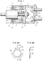
- Fig. 7 shows a sectional view showing a essential part of a magnet switch for illustarting a prototype.
- a cylindrical plunger 51 is disposed within a cylindrical sleeve 52 in coaxial relation thereto, and the plunger 51 is movable along an axis thereof within the sleeve 52.
- An exciting coil 54 wound on a bobbin 53 of an electrically-insulative material is provided around an outer periphery of the sleeve 52.
- a frame 55 of a magnetic material is provided to surround the exciting coil 54.
- the frame 55 has a bottom plate portion 551 provided in contact with the outer peripheral surface of the sleeve 52 on an end portion of the frame 55.
- a cushion spring 56 which urges the exciting coil 54 with the bobbin 53 toward a stationary core (not shown), i.e., in a right direction in Fig. 7.
- the exciting coil 54 is adapted to be located in a fixed position within the frame 55.
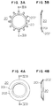
- the cushion spring 56 is formed, for example, by cutting a ring-shaped piece out of a resilient metal sheet bent to a wavy configuration, as shown in Figs. 8A and 8B.
- the cushion spring 56 is made, for example, of steel.
- a magnetic gap ⁇ a is formed between the bottom plate portion 551 of the frame 51 and the plunger 51.
- a main magnetic flux A exists at that portion of the bottom plate portion 551 disposed in opposed relation to the outer peripheral surface of the plunger 51. Since the area of this opposed portion is limited, a magnetic resistance of the magnetic gap ⁇ a is large, so that a leakage magnetic flux B inevitably develops.
- This leakage magnetic flux B flows in a magnetic path of a high magnetic resistance (i.e., in the air), and this means that the loss of a magnetomotive force is large.
- the cushion spring 56 is made of steel capable of constructing a magnetic path, and is provided in a stable state of loosely fitted on the outer periphery of the sleeve 52. Therefore, a large gap ⁇ b is formed between the spring 56 and the plunger 51, and therefore the cushion spring 56 does not serve as part of the magnetic circuit.
- a magnet switch includes a cylindrical plunger of a magnetic material movable along an axis thereof, a stationary core of a magnetic material provided in opposed relation to one end of the plunger, and an exciting coil being wound on a bobbin adapted to surround an outer periphery of the plunger. And a frame is provided in surrounding relation to the exciting coil, one end portion of the frame being connected to the stationary core, the frame having a bottom plate portion formed at the other end thereof, and the bottom plate portion having an opening whose inner diameter is provided close to the outer periphery of the plunger, and a cushion spring is interposed between the bottom plate portion of the frame and the bobbin.
- the cushion spring includes a cylindrical inner peripheral wall disposed around the outer periphery of the plunger in closely spaced relation to the outer periphery, a contact portion held in contact with one of the bottom plate portion of the frame and the bobbin, and an urging portion urging the bobbin away from the bottom plate portion.
- the frame surrounding the exciting coil is disposed very close to the plunger at its bottom plate portion, and the contact portion of the cushion spring is held in contact with the bottom plate portion of the frame, and the inner peripheral portion of the cushion spring is disposed very close to the outer periphery of the plunger. Therefore, a main magnetic flux is formed between the bottom plate portion of the frame and the plunger, and also a main magnetic flux is formed between the inner peripheral wall of the cushion spring and the plunger. As a result, a sufficient magnetic pull force is exerted on the plunger. In this case, only the cushion spring is provided between the bottom plate portion of the frame and the bobbin having the exciting coil wound thereon, and therefore the axial length of the magnet switch does not need to be increased, and a compact design of the magnet switch can be achieved.
- Fig. 1 shows a cross-sectional construction of a magnet switch.
- This magnet switch provides with a cylindrical plunger 11 made of a magnetic material such as soft steel.
- the plunger 11 is provided in a cylindrical sleeve 12 of a non-magnetic material such as brass, and is guided by the sleeve 12 so as to move along an axis thereof.
- a stationary core 13 made of a magnetic material is partly fitted in one end portion of the sleeve 12, and an opening is formed through a central portion of the stationary core 13, and a drive shaft 14 projecting from one end face of the plunger 11 is passed through this opening.
- An umbrella-shaped movable contact 15 of a trapezoidal cross-sectional shape is provided in opposed relation to that side of the stationary core 13 facing away from the plunger 11, and is integrally connected to the drive shaft 14.
- a compression spring 16 is interposed between the plunger 11 and the stationary core 13, and the plunger 11 is normally urged by this spring 16 in a direction away from the stationary core 13.
- the stationary core 13 is provided to be fitted in one end portion of a cylindrical frame 17 of a magnetic material.
- An exciting coil 18 is provided to be contained within the frame 17.
- the exciting coil 18 is wound on a bobbin 19 of an electrically-insulative material provided to be fitted on the outer periphery of the sleeve 12.
- the frame 17 has a bottom plate portion 171 covering one end surface of the bobbin 19, and the bottom plate portion 171 has an opening at the central portion of this bottom plate portion 171. Its inner peripheral surface is disposed in contact with the outer peripheral surface of the sleeve 12.
- a cushion spring 20 is interposed between the bottom plate portion 171 and the bobbin 19 having the exciting coil 18 wound thereon. The cushion spring 20 urges the bobbin 19 toward the stationary core 13 to hold the exciting coil 18 in a predetermined position.
- Figs. 2A and 2B show the construction of the cushion spring 20.
- This spring 20 is made of magnetic steel, that is, a material allowing a magnetic flux to pass therethrough.
- the cushion spring 20 has a ring portion 201 (which serves as a contact portion) having such an inner diameter that the ring portion 201 is disposed in contact with the outer peripheral surface of the sleeve 12.
- a plurality of (three in the drawings) spring portions 202 are formed on the outer periphery of the ring portion 201. More specifically, each of spring portions 202 is defined by an arcuate portion (narrow piece) and an arm portion interconnecting this arcuate portion and the ring portion 201. Each arcuate portion is offset from the plane of the ring portion 201, and is slanting toward the bobbin 19. The three arcuate portions are disposed generally on an imaginary circle concentric with the ring portion 201.
- the cushion spring 20 is interposed between the bottom plate portion 171 of the frame 17 and the bobbin 19 as described above, and in this condition one side or surface of the ring portion 201 is held in contact with the bottom plate portion 171, and the inner peripheral surface of the ring portion 201 is held in contact with the outer peripheral surface of the sleeve 12.
- the inner peripheral wall or surface of the ring portion 201 is disposed sufficiently close to the outer peripheral surface of the plunger 11.
- the cushion spring 20 used here may have various shapes.
- Figs. 3A and 3B show a modified cushion spring 20 in which a plurality of arms (narrow pieces), which serve as spring portions 202, extend generally radially outwardly from a ring portion 201.
- Figs. 4A and 4B show another modified cushion spring 20 of a belleville spring type in which an annular flange, which serves as a spring portion 202, is formed on an entire outer periphery of a ring portion 201, the flange 202 projecting out of the plane of the ring portion 201.
- a cover 21 made, for example, of a resin is mounted on the end portion of the frame 17 in which the stationary core 13 fits, and a pair of fixed contacts 221 and 222 are provided within the cover 21 generally in opposed relation to the movable contact 15.
- the movable contact 15 is moved against the bias of the spring 16, electrical connection between the two fixed contacts 221 and 222 is established through the movable contact 15 to form an electrical circuit between terminals 231 and 232 to thereby supply electric drive power to a starter motor (not shown).
- the sleeve 12 made of a non-magnetic material is interposed between the frame 17 and the plunger 11. Therefore, a magnetic resistance greatly increases at the sleeve 12 to cause a magnetic flux loss.
- Such a magnetic resistance can be reduced by increasing the cross-sectional area of a magnetic path disposed adjacent to the outer periphery of the plunger 11. For example, if a cylindrical portion is formed on the central portion of the bottom plate portion 171 of the frame 17, and extends along the outer peripheral surface of the plunger 11, the area of overlap between this cylindrical portion and the outer peripheral surface of the plunger 11 is increased, so that the magnetic resistance is decreased.
- the frame 17 if the frame 17 is to be formed, for example, by pressing, the frame 17 must be shaped in such a manner that the cylindrical portion extends perpendicularly from the central portion of the bottom plate portion 171 of the frame 17, and at the same time the central hole for the passage of the plunger 11 therethrough must be formed by punching. Therefore, the pressing process becomes complicated.
- the axial length of the frame 17 is increased because of the provision of the cylindrical portion, so that the magnet switch has an increased size.
- one side or surface of the ring portion 201 of the cushion spring 20 facing away from the bobbin 19 is pressed against the bottom plate portion 171 of the frame 17 by its own resilient force, so that this ring portion 201 can be used as a magnetic path.
- the inner diameter of the ring portion 201 of the cushion spring 20 is generally equal to the outer diameter of the sleeve 12, so that a gap between the inner peripheral surface of the ring portion 201 of the cushion spring 20 and the outer peripheral surface of the plunger 11 is very small. Namely, this gap has such a minimum value as to allow the ring portion 201 to fit on the sleeve 12. With this arrangement, the cross-sectional area of the magnetic path between the ring portion 201 of the cushion spring 20 and the plunger 11 can be efficiently increased.
- Fig. 5 shows this magnetic path-constructing portion on an enlarged scale.
- the gap ⁇ a between the bottom plate portion 171 of the frame 17 and the outer peripheral surface of the plunger 11 is equal to the gap ⁇ b between the inner peripheral surface of the ring portion 201 of the cushion spring 20 and the outer peripheral surface of the plunger 11 (the value of the gaps ⁇ a and ⁇ b is determined mostly in accordance with the thickness of the sleeve 12.), and the inner peripheral surface of the ring portion 201 is disposed sufficiently close to the outer peripheral surface of the plunger 11. Therefore, the cross-sectional area of the magnetic paths corresponding to the thickness of the bottom plate portion 171 and the thickness of the ring portion 201 is obtained, and a main magnetic flux A is formed also at this portion.
- the frame 17 is made of soft steel, and the cushion spring 20 is made of spring steel or tool steel because of the necessity of a spring force. Therefore, the permeability of the cushion spring 20 is lower than that of the frame 17; however, the magnetic resistance of the sleeve 12 made of a non-magnetic material is very large with respect to the permeability of the spring 20.
- a curve A represents the results obtained with the magnet switch of the present invention
- a curve B represents the results with the magnet switch having the cylindrical portion projecting to the bottom plate portion of the frame as compared with the core A
- a curve C represents results with a prototype magnet switch as shown in Fig. 7.
- the cushion springs 20 shown in Figs. 2A to 4B can be produced by stamping a steel sheet in a pressing operation, and the spring portion 202 can be obtained by a bending operation similar to that used in the production of the cushion spring 56 shown in Figs. 8A, 8B. Furthermore, the cushion spring 20 can be installed in a single step, and therefore the pull force improvement of the magnet switch according to the invention will be accomplished at small cost.
- the cushion spring 20 serves as the magnetic path, and therefore if the other parts are the same as those of the conventional construction, the number of turns of the exciting coil 18 can be reduced, which contributes to a compact and lightweight design.
- Each of the above-mentioned cushion springs 20 may be mounted reversely so that the ring portion 201 is held against the bobbin 19 whereas the spring portion 202 is held against the bottom plate portion 171.
- a further modified cushion spring is similar in configuration to the cushion spring of Figs. 8A and 8B except that an inner periphery wall or surface thereof is disposed in closely spaced relation to the outer periphery of the plunger.
- the magnetic pull force acting on the plunger is enhanced without increasing the overall size of the magnet switch.
- the highly-reliable switch device of a more compact construction can be provided, and therefore can be used in a sufficiently reliable manner as a switch mechanism for a starter motor or the like.
- a magnet switch for a starter device includes a plunger on which a sufficient pull force can be exerted.
- the plunger drives a movable contact, and is guided by a sleeve so as to move therealong.
- An excited coil wound on a bobbin is provided around an outer periphery of the sleeve.
- the exciting coil is covered by a cylindrical frame of a magnetic material, and a bottom plate portion of the frame has an opening fitted on the outer periphery of the sleeve.
- a cushion spring is interposed between the bottom plate portion of the frame and the bobbin to hold the exciting coil in a predetermined position.
- the cushion spring has an annular portion disposed in contact with the bottom plate portion and the outer periphery of the sleeve, and a magnetic path can be formed between the annular portion and the plunger.
Landscapes
- Physics & Mathematics (AREA)
- Electromagnetism (AREA)
- Electromagnets (AREA)
- Push-Button Switches (AREA)
Applications Claiming Priority (2)
| Application Number | Priority Date | Filing Date | Title |
|---|---|---|---|
| JP20569592A JP3324145B2 (ja) | 1992-07-31 | 1992-07-31 | マグネットスイッチ |
| JP205695/92 | 1992-07-31 |
Publications (3)
| Publication Number | Publication Date |
|---|---|
| EP0581277A2 true EP0581277A2 (de) | 1994-02-02 |
| EP0581277A3 EP0581277A3 (en) | 1994-07-27 |
| EP0581277B1 EP0581277B1 (de) | 1998-10-07 |
Family
ID=16511182
Family Applications (1)
| Application Number | Title | Priority Date | Filing Date |
|---|---|---|---|
| EP93112141A Expired - Lifetime EP0581277B1 (de) | 1992-07-31 | 1993-07-29 | Magnetschalter |
Country Status (4)
| Country | Link |
|---|---|
| US (1) | US5428330A (de) |
| EP (1) | EP0581277B1 (de) |
| JP (1) | JP3324145B2 (de) |
| DE (1) | DE69321419T2 (de) |
Cited By (3)
| Publication number | Priority date | Publication date | Assignee | Title |
|---|---|---|---|---|
| FR2764433A1 (fr) * | 1997-06-10 | 1998-12-11 | Valeo Equip Electr Moteur | Contacteur de demarreur de vehicule automobile |
| FR2795859A1 (fr) * | 1999-06-30 | 2001-01-05 | Valeo Equip Electr Moteur | Contacteur pour un demarreur de vehicule automobile et demarreur comportant un tel contacteur |
| DE10057809B4 (de) * | 1999-11-24 | 2009-10-15 | Denso Corporation, Kariya-City | Magnetschalter mit einer harzartigen Schalterabdeckung |
Families Citing this family (14)
| Publication number | Priority date | Publication date | Assignee | Title |
|---|---|---|---|---|
| EP0706195B1 (de) * | 1994-10-05 | 1999-05-06 | Denso Corporation | Anlauf-Relais |
| US5631613A (en) * | 1994-11-22 | 1997-05-20 | Nippondenso Co., Ltd. | Magnet switch for engine starter |
| JP3562072B2 (ja) * | 1994-11-29 | 2004-09-08 | 株式会社デンソー | スタータ |
| CN1064174C (zh) * | 1995-10-12 | 2001-04-04 | 西门子公司 | 磁体减振装置 |
| US5905422A (en) * | 1996-11-26 | 1999-05-18 | Siemens Electromechanical Components, Inc. | Relay adjustment structure |
| JP2000322999A (ja) * | 1999-05-12 | 2000-11-24 | Mitsubishi Electric Corp | スタータ用マグネットスイッチ |
| JP3861672B2 (ja) * | 2000-12-13 | 2006-12-20 | 株式会社デンソー | 電磁弁およびその電磁弁を用いた流体制御装置 |
| JP4490897B2 (ja) | 2005-10-14 | 2010-06-30 | 愛三工業株式会社 | 電子制御式スロットル弁装置 |
| CN103026447B (zh) | 2010-03-15 | 2016-06-22 | 欧姆龙株式会社 | 线圈端子 |
| CN101881680B (zh) * | 2010-06-03 | 2011-12-07 | 南京工业职业技术学院 | 一种多功能压力检测与测量开关 |
| US9368266B2 (en) * | 2014-07-18 | 2016-06-14 | Trumpet Holdings, Inc. | Electric solenoid structure having elastomeric biasing member |
| CN111952121A (zh) * | 2020-08-14 | 2020-11-17 | 广东井得电机股份有限公司 | 一种防止粘连的继电器 |
| DE102023136122A1 (de) * | 2023-12-20 | 2025-06-26 | Mahle International Gmbh | Magnetschalter für einen Fahrzeuganlasser |
| CN119145716B (zh) * | 2024-11-21 | 2025-01-28 | 常州迈特运控电机有限公司 | 一种带有简易缓冲端结构的电磁铁插销装置 |
Family Cites Families (13)
| Publication number | Priority date | Publication date | Assignee | Title |
|---|---|---|---|---|
| GB1253822A (en) * | 1968-05-27 | 1971-11-17 | Lucas Industries Ltd | Electromagnets |
| US3755766A (en) * | 1972-01-18 | 1973-08-28 | Regdon Corp | Bistable electromagnetic actuator |
| US3815060A (en) * | 1973-04-19 | 1974-06-04 | Square D Co | Electromagnetic contactor for battery powered vehicles |
| US4124192A (en) * | 1977-02-28 | 1978-11-07 | Ambac Industries Incorporated | Time delay solenoid operated valve |
| JPS5558507A (en) * | 1978-10-26 | 1980-05-01 | Nachi Fujikoshi Corp | Oil-immersed solenoid |
| US4251789A (en) * | 1979-09-04 | 1981-02-17 | General Electric Company | Circuit breaker trip indicator and auxiliary switch combination |
| US4293835A (en) * | 1980-01-28 | 1981-10-06 | Roper Corporation | Solenoid for an electric starting motor for garden tractor or the like |
| DE3030776A1 (de) * | 1980-08-14 | 1982-03-25 | Robert Bosch Gmbh, 7000 Stuttgart | Elektromagnetischer schalter, insbesondere fuer elektrische andrehvorrichtungen von brennkraftmaschinen |
| US4632358A (en) * | 1984-07-17 | 1986-12-30 | Eaton Corporation | Automotive air conditioning system including electrically operated expansion valve |
| DE3632469A1 (de) * | 1986-09-24 | 1988-03-31 | Bosch Gmbh Robert | Elektromagnetischer schalter, insbesondere fuer andrehvorrichtungen von brennkraftmaschinen |
| JPS63280851A (ja) * | 1987-05-14 | 1988-11-17 | Nippon Denso Co Ltd | スタ−タ用マグネットスイッチ |
| JPH03157576A (ja) * | 1989-11-15 | 1991-07-05 | Aisin Aw Co Ltd | 三方電磁弁及びその製造方法 |
| US5217047A (en) * | 1991-05-30 | 1993-06-08 | Coltec Industries Inc. | Solenoid operated pressure regulating valve |
-
1992
- 1992-07-31 JP JP20569592A patent/JP3324145B2/ja not_active Expired - Fee Related
-
1993
- 1993-07-29 DE DE69321419T patent/DE69321419T2/de not_active Expired - Lifetime
- 1993-07-29 EP EP93112141A patent/EP0581277B1/de not_active Expired - Lifetime
-
1994
- 1994-10-11 US US08/320,789 patent/US5428330A/en not_active Expired - Lifetime
Cited By (3)
| Publication number | Priority date | Publication date | Assignee | Title |
|---|---|---|---|---|
| FR2764433A1 (fr) * | 1997-06-10 | 1998-12-11 | Valeo Equip Electr Moteur | Contacteur de demarreur de vehicule automobile |
| FR2795859A1 (fr) * | 1999-06-30 | 2001-01-05 | Valeo Equip Electr Moteur | Contacteur pour un demarreur de vehicule automobile et demarreur comportant un tel contacteur |
| DE10057809B4 (de) * | 1999-11-24 | 2009-10-15 | Denso Corporation, Kariya-City | Magnetschalter mit einer harzartigen Schalterabdeckung |
Also Published As
| Publication number | Publication date |
|---|---|
| US5428330A (en) | 1995-06-27 |
| EP0581277A3 (en) | 1994-07-27 |
| DE69321419T2 (de) | 1999-04-29 |
| EP0581277B1 (de) | 1998-10-07 |
| JP3324145B2 (ja) | 2002-09-17 |
| JPH0652772A (ja) | 1994-02-25 |
| DE69321419D1 (de) | 1998-11-12 |
Similar Documents
| Publication | Publication Date | Title |
|---|---|---|
| EP0581277B1 (de) | Magnetschalter | |
| US7038563B2 (en) | Electromagnetic switch for starter | |
| US5424700A (en) | Starter motor contactor for a motor vehicle internal combustion engine | |
| EP3264437B1 (de) | Elektromagnetisches relais | |
| CN105531788A (zh) | 电磁继电器 | |
| US5631613A (en) | Magnet switch for engine starter | |
| EP0210789B1 (de) | Elektromagnetischer Schalter | |
| JP2002168166A (ja) | スタータ用マグネットスイッチ | |
| JP5659625B2 (ja) | ソレノイド装置 | |
| US5039967A (en) | Magnetic switch | |
| CN218996625U (zh) | 继电器及其推杆机构 | |
| US6239678B1 (en) | Starter magnet switch | |
| JP2002260512A (ja) | マグネットスイッチ | |
| US5623239A (en) | Electrical contactor spring | |
| JP4121088B2 (ja) | スタータ用電磁スイッチ | |
| JP3440517B2 (ja) | マグネットスイッチ | |
| US6590483B2 (en) | Electromagnetic solenoid actuator | |
| JP3917807B2 (ja) | スタータ用マグネチックスイッチの製造方法 | |
| WO2020261635A1 (ja) | ホーン | |
| JPH05325759A (ja) | 電磁継電器 | |
| JP4289770B2 (ja) | マグネットスイッチ | |
| JPS6346999Y2 (de) | ||
| JP2022144146A (ja) | 電磁継電器 | |
| JP2002268643A (ja) | 車両用ホーン | |
| JP2920996B2 (ja) | 電磁リレー |
Legal Events
| Date | Code | Title | Description |
|---|---|---|---|
| PUAI | Public reference made under article 153(3) epc to a published international application that has entered the european phase |
Free format text: ORIGINAL CODE: 0009012 |
|
| AK | Designated contracting states |
Kind code of ref document: A2 Designated state(s): DE GB IT |
|
| PUAL | Search report despatched |
Free format text: ORIGINAL CODE: 0009013 |
|
| AK | Designated contracting states |
Kind code of ref document: A3 Designated state(s): DE GB IT |
|
| 17P | Request for examination filed |
Effective date: 19940728 |
|
| GRAG | Despatch of communication of intention to grant |
Free format text: ORIGINAL CODE: EPIDOS AGRA |
|
| 17Q | First examination report despatched |
Effective date: 19970204 |
|
| RAP1 | Party data changed (applicant data changed or rights of an application transferred) |
Owner name: DENSO CORPORATION |
|
| GRAG | Despatch of communication of intention to grant |
Free format text: ORIGINAL CODE: EPIDOS AGRA |
|
| GRAG | Despatch of communication of intention to grant |
Free format text: ORIGINAL CODE: EPIDOS AGRA |
|
| GRAH | Despatch of communication of intention to grant a patent |
Free format text: ORIGINAL CODE: EPIDOS IGRA |
|
| GRAH | Despatch of communication of intention to grant a patent |
Free format text: ORIGINAL CODE: EPIDOS IGRA |
|
| GRAA | (expected) grant |
Free format text: ORIGINAL CODE: 0009210 |
|
| ITF | It: translation for a ep patent filed | ||
| AK | Designated contracting states |
Kind code of ref document: B1 Designated state(s): DE GB IT |
|
| REF | Corresponds to: |
Ref document number: 69321419 Country of ref document: DE Date of ref document: 19981112 |
|
| REG | Reference to a national code |
Ref country code: GB Ref legal event code: 746 Effective date: 19990615 |
|
| PLBE | No opposition filed within time limit |
Free format text: ORIGINAL CODE: 0009261 |
|
| STAA | Information on the status of an ep patent application or granted ep patent |
Free format text: STATUS: NO OPPOSITION FILED WITHIN TIME LIMIT |
|
| 26N | No opposition filed | ||
| REG | Reference to a national code |
Ref country code: GB Ref legal event code: IF02 |
|
| PGFP | Annual fee paid to national office [announced via postgrant information from national office to epo] |
Ref country code: GB Payment date: 20110727 Year of fee payment: 19 Ref country code: DE Payment date: 20110727 Year of fee payment: 19 |
|
| PGFP | Annual fee paid to national office [announced via postgrant information from national office to epo] |
Ref country code: IT Payment date: 20110721 Year of fee payment: 19 |
|
| GBPC | Gb: european patent ceased through non-payment of renewal fee |
Effective date: 20120729 |
|
| PG25 | Lapsed in a contracting state [announced via postgrant information from national office to epo] |
Ref country code: GB Free format text: LAPSE BECAUSE OF NON-PAYMENT OF DUE FEES Effective date: 20120729 Ref country code: DE Free format text: LAPSE BECAUSE OF NON-PAYMENT OF DUE FEES Effective date: 20130201 |
|
| REG | Reference to a national code |
Ref country code: DE Ref legal event code: R119 Ref document number: 69321419 Country of ref document: DE Effective date: 20130201 |
|
| PG25 | Lapsed in a contracting state [announced via postgrant information from national office to epo] |
Ref country code: IT Free format text: LAPSE BECAUSE OF NON-PAYMENT OF DUE FEES Effective date: 20120729 |