EP0581496A2 - Effusionsquelle für Molekularstrahl-Epitaktie mit Heizungselemente zur Erhaltung von Temperatur Gradienten - Google Patents
Effusionsquelle für Molekularstrahl-Epitaktie mit Heizungselemente zur Erhaltung von Temperatur Gradienten Download PDFInfo
- Publication number
- EP0581496A2 EP0581496A2 EP93305582A EP93305582A EP0581496A2 EP 0581496 A2 EP0581496 A2 EP 0581496A2 EP 93305582 A EP93305582 A EP 93305582A EP 93305582 A EP93305582 A EP 93305582A EP 0581496 A2 EP0581496 A2 EP 0581496A2
- Authority
- EP
- European Patent Office
- Prior art keywords
- source
- crucible
- temperature
- heater
- horizontal
- Prior art date
- Legal status (The legal status is an assumption and is not a legal conclusion. Google has not performed a legal analysis and makes no representation as to the accuracy of the status listed.)
- Withdrawn
Links
Images






Classifications
-
- C—CHEMISTRY; METALLURGY
- C30—CRYSTAL GROWTH
- C30B—SINGLE-CRYSTAL GROWTH; UNIDIRECTIONAL SOLIDIFICATION OF EUTECTIC MATERIAL OR UNIDIRECTIONAL DEMIXING OF EUTECTOID MATERIAL; REFINING BY ZONE-MELTING OF MATERIAL; PRODUCTION OF A HOMOGENEOUS POLYCRYSTALLINE MATERIAL WITH DEFINED STRUCTURE; SINGLE CRYSTALS OR HOMOGENEOUS POLYCRYSTALLINE MATERIAL WITH DEFINED STRUCTURE; AFTER-TREATMENT OF SINGLE CRYSTALS OR A HOMOGENEOUS POLYCRYSTALLINE MATERIAL WITH DEFINED STRUCTURE; APPARATUS THEREFOR
- C30B23/00—Single-crystal growth by condensing evaporated or sublimed materials
- C30B23/02—Epitaxial-layer growth
- C30B23/06—Heating of the deposition chamber, the substrate or the materials to be evaporated
- C30B23/066—Heating of the material to be evaporated
-
- C—CHEMISTRY; METALLURGY
- C23—COATING METALLIC MATERIAL; COATING MATERIAL WITH METALLIC MATERIAL; CHEMICAL SURFACE TREATMENT; DIFFUSION TREATMENT OF METALLIC MATERIAL; COATING BY VACUUM EVAPORATION, BY SPUTTERING, BY ION IMPLANTATION OR BY CHEMICAL VAPOUR DEPOSITION, IN GENERAL; INHIBITING CORROSION OF METALLIC MATERIAL OR INCRUSTATION IN GENERAL
- C23C—COATING METALLIC MATERIAL; COATING MATERIAL WITH METALLIC MATERIAL; SURFACE TREATMENT OF METALLIC MATERIAL BY DIFFUSION INTO THE SURFACE, BY CHEMICAL CONVERSION OR SUBSTITUTION; COATING BY VACUUM EVAPORATION, BY SPUTTERING, BY ION IMPLANTATION OR BY CHEMICAL VAPOUR DEPOSITION, IN GENERAL
- C23C14/00—Coating by vacuum evaporation, by sputtering or by ion implantation of the coating forming material
- C23C14/22—Coating by vacuum evaporation, by sputtering or by ion implantation of the coating forming material characterised by the process of coating
- C23C14/24—Vacuum evaporation
- C23C14/243—Crucibles for source material
Definitions
- This invention is primarily concerned with an effusion source having its main application in molecular beam epitaxy equipment and a method for the generation of atomic and/or molecular beams from chemical elements or compounds such that the beams, when directed upon a substrate, produce grown layers (typically thin epitaxial films) of improved quality when compared to prior known layers.
- MBE Molecular Beam Epitaxy
- the source of this invention and its features are not limited to use in ultra high vacuum (UHV) and/or MBE applications.
- the source includes a crucible, one end of which is open, the other end of which is sealed if using solid or liquid materials to create the beam or alternatively, if using gaseous or liquid materials or if using a remote source for materials, then with an input feed system at the normally closed end.
- the crucible is surrounded by a source body containing a thermocouple, crucible heater and other internal construction designed to provide a specific thermal environment for the crucible and for materials used therein.
- MBE refers to Molecular Beam Epitaxy and to related processes, techniques and variations such as MOMBE (Metal Organic Molecular Beam Epitaxy), GSMBE (Gas Source MBE) and CBE (Chemical Beam Epitaxy).
- MOMBE Metal Organic Molecular Beam Epitaxy
- GSMBE Gas Source MBE
- CBE Certial Beam Epitaxy
- source molecular beam source
- effusion cell Knudsen cell and furnace refer to a device used to generate or create a molecular beam.
- molecular beam is used to represent all such atomic, molecular, or combinations of atomic and molecular specie that are effused from any of the above sources.
- grown film refers to a layer that is deposited upon and/or chemically reacts with a substrate held in the path of a molecular beam source.
- thermal shield thermal partition thermal baffle and thermal sink are used to describe a physical element that serves to modify the temperature distribution within the body of said source in a specific manner by impeding or expediting the flow of heat.
- inverted temperature gradient is used to describe a thermal profile in a source in which the temperature is highest at the open end and decreases toward its rear or base end.
- the improvements in the source are found in 1) the crucible heater design and the location of the heating mechanism within the source; 2) thermal sinks and their positions within the source and their positional relationships to the crucible; and 3) crucible designs.
- Crucible heater embodiments of this invention provide: 1) increased thermal energy density when compared to prior art designs; 2) specific temperature profiles that accommodate source material asymmetries (with respect to the source axis) and, 3) in the case of liquid source materials, mechanisms that permit source material density differences to create improved beam purity.
- Thermal sinks are used to augment and influence temperature regions. An inverted (as compared to prior art) temperature gradient within the cell is achieved in the practice of this invention and this contributes considerably to the quality of the grown films and generally to the process improvements of this invention.
- New crucible embodiments are intended to segregate unwanted materials by density or by differences in materials in liquid source melts.
- the process improvements over the prior art created by the source of this invention and its embodiments include: a reduction in beam flux contaminants; betterfilm properties at highergrowth rates; and a reduction in growth defects in films made using this invention.
- Effusion sources of the prior art consist of three main elements: a mounting flange, a source body, and a crucible.
- the mounting flange positions the source in the vacuum chamber, provides a vacuum seal, and contains the power and thermocouple feed throughs.
- the source body consists of a crucible heater, a thermocouple, appropriate support structures and external, thermal insulating layers.
- the crucible is situated within the source body and holds materials to create the beam. Appropriate materials when positioned within the source when heated will effuse from the crucible mouth as a molecular beam.
- Heating elements of the prior art whether wire, foil or solid (e.g. graphite), inductive or non-inductive, or whether composed of single or multiple sections, have been symmetrical with respect to the source body's axis. Generally uniform heating elements extend along the source body length except for accommodations for power input connections and connections between heating sections.
- the intent has generally been to produce an isothermal temperature zone within the source.
- a primary objective is to create a temperature inversion within the source.
- crucibles are maintained in an angular position during the creation of the molecular beam.
- efforts are made by manufacturers to achieve isothermal conditions within the crucible for purposes of obtaining uniform material heating.
- the temperature in such cases varies along the source axis.
- the effect of this in respect to a crucible at an angle to the horizontal is to create a temperature difference across the surface of the melted materials since the surface extends across an area oblique to the axis (generally the surface will conform to a horizontal plane parallel to the ground) and thus the melted material will be effected by temperature gradients along the axis itself and its surface.
- the effusing surface of the source material will otherwise always lie in a position as to make an oblique angle with the source body and crucible axis. This angle typically varies between approximately 10 and 45 degrees, depending on source orientation within the process chamber.
- the resulting temperature gradients can be sufficient to generate free convection on the surface of the melt in the liquid source materials. This has been observed within crucibles containing liquid effusing materials. Free convection, it is currently believed, causes the development of impure molecular beams by assisting processes detrimental to beam purity which in turn affects the composition and structure of the growing film and degrades its qualities.
- Heating element embodiments of the prior art have been of wire, foil or solid conductors. In many cases these elements have been configured so as to yield a near null magnetic field when driven by an AC power source. This may be important to the proper operation of nearby magnetic field sensitive instrumentation associated with MBE. Alternatively, the heating elements can be DC driven, but this is usually a more expensive option and DC can also cause breakdown of ionic insulators. At least one prior art device involves the use of a solenoidal (about the crucible axis) heating element requiring a DC power source. There are no known examples in the prior art of a heater with solenoidal elements configured to produce equal, adjacent and canceling fields.
- Some crucible heaters currently in use are composed of two axially symmetric elements (see, for example, U.S. 5,034,604).
- the heating element closest to the open end of the crucible is designed to produce a thermal energy density sufficient to counter the radiation losses.
- a single symmetrical heater element would typically produce a temperature gradient which is hottest at the closed end and coolest at the open end.
- single heating element sources of the prior art will allow gallium droplets to form at the crucible open end (due to condensation on the relatively cool surface). These droplets have been associated with degraded grown film properties (more defects) and are undesirable.
- a higher heat input near the open end of the source compensates the high radiation losses at that end and produces a more nearly isothermal crucible temperature. Raising the crucible temperature further near the open end will eventually invert the thermal gradient. To prevent gallium droplet formation, the front must be hot enough so that reevaporation exceeds the incident molecularflux. To suppress convection currents, the uppermost source material must be warmer than the material immediately below.
- the higher heating element temperature causes greater outgassing which may in turn cause deterioration of the film being grown and premature failure of the heater and/or its insulating supports.
- the heating elements of the present invention generally run cooler (at a given heat output) because of the unique construction of the heating elements themselves.
- the source of this invention can produce an inverted temperature gradient and lower winding temperatures in all embodiments, minimizing outgassing, extending heating element life, and producing low grown film defect densities.
- This invention is related to and has as its primary objective the production of improved molecular beams.
- Such molecular beams are directed at a substrate surface for the purpose of growing a layer or film with specific mechanical and electrical properties. This type of growth usually takes place in an ultra-high vacuum system.
- the source of this invention is primarily for the generation of molecular beams and especially those created in MBE processes.
- One particular example is the generation of gallium beams for the growth of gallium arsenide and related compound semiconductor materials.
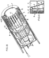
- the source comprises a flange assembly 1, a main body 2, a crucible 3, and a thermocouple assembly 4.
- the main source body 2 consists of two, asymmetric crucible heating elements, 5 and 15; insulating heater element supports 6, and outer thermal shields 8.
- Front heating element 5 is constructed so as to heat the source cavity 7 adjacent to the crucible open end.
- Rear heating element 15 is constructed to heat the remainder of the crucible.
- Optional thermal shields 18 limit heating of the closed crucible end.
- heating elements 5 and 15 are shaped to uniformly heat the melt in a plane which conforms to the surface plane of the melt in position in the crucible.
- the crucible heaters of this invention have the ability to invert the crucible temperature gradient of the prior art.
- Heating element segments 5 and 15 are paired with opposite pitch directions and equal lengths to minimize the net magnetic field and self-inductance. Element pairs can be of different lengths in order to achieve an asymmetric configuration.
- Insulators 6 maintain the solenoid segment positions. These insulators may be of rectangular, circular, or tubular cross-section and of any insulating material thatwill contribute a minimum contamination to the process.
- Rectangular insulators oriented to permit maximum radiation transfer to the crucible cavity are shown in detail in FIGS. 1b and 1c.
- Insulators 6 are captured at their ends by insulating rings 16 of pyrolytic boron nitride (PBN) or other suitable material.
- Refractory metal wire 17 is used to secure the insulators 6 to the rings 16 and, in the case of rectangular insulators 6, to orient the long insulator cross-section with radials to the source body axis.
- Heating element asymmetry can be optimized to each unique source orientation.
- the heater element 5 is illustrated as solenoidal wire and element 15 has straight wire sections, either element can, in general, be any number of alternate configurations and achieve the same results and the objectives of this invention.
- Internal thermal shields 18 are optional. These may be tapered and layered shields which augment an inverted temperature gradient by progressively impeding heat flow toward the closed crucible end. An inverted temperature gradient is possible without internal shields, but can be achieved to a greater extent when they are used in the system.
- the shield 18 may also extend to a point close to the open end of the crucible 3. When so coextensive with the source more effusing material can be handled by the crucible 3 and the inverted temperature gradient is effectively achieved resulting in less defects in the grown layers.
- the solenoid element design permits a higher density of thermal radiation when compared to the prior art.
- the amount of radiation density can be varied throughout the heating element by varying the wire diameter, solenoid diameter and/orthe pitch, and the spacing between segment pairs.
- the heater wire material useful in this invention may comprise any of the high temperature refractory metals which may for example comprise: tantalum, molybdenum or tungsten. Tantalum is usually preferred because its mechanical properties allow it to be formed easily at room temperature.
- FIG. 5a and 5b shows experimental data to support the above results for a gallium molecular beam used in the growth of gallium arsenide films.
- FIG. 5a is a typical result of total defect density across a one micron thick gallium arsenide film when grown using a gallium source of the prior art.
- FIG. 5b is a histogram of 53 wafers where the average total defect density per micron of film growth is measured for each wafer.
- the average total defect density per wafer is reduced by approximately two orders of magnitude.
- the exact mechanism responsible for the low defect results has not been determined. While several mechanisms have been suggested it is our opinion that in respect to gallium, convection currents and chemical reactions involving gallium oxides are responsible. It is also our belief that the inverse temperature profile created by this invention suppresses these mechanisms. It has been an observation of the prior art that the defect density increases with the source temperature (higher effusion flux rates) precluding film growth at higher rates. The art of this invention, because of its suppression of defect density, allows film growth at higher rates and promises to increase MBE system throughput as a result.
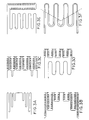
- FIG. 2a shows a second embodiment of the source of this invention wherein the heating element 15 is a single solenoidal winding of varying pitch. Varying the pitch allows the radiation heat density (and temperature profile) of the crucible cavity to be affected. Asymmetrical heater configurations and inverted temperature profiles are possible. The heating element design may incorporate segment designs of the prior art as well as solenoidal designs in order to achieve a given temperature profile.
- FIG. 2b shows a three zone asymmetrical heater in flat (opened) pattern.
- FIGS. 3a through 3f illustrate the variety of heater configurations available to produce different thermal energy zones when the prior art is combined with the solenoidal element design of this invention.
- FIG. 4 shows one embodiment of the source of this invention with a thermal sink 309.
- Thermal sinks can be arranged anywhere within the source body depending on the temperature profile desired.
- the sink as applied in this invention, is any passive construction which will decrease the thermal impedance (and thus increase the flow of heat) and lower the temperature difference between a specific source region and the ambient thermal environment.
- the sink region can be an aperture open to a region of lower temperature 310.
- This cooler region can be maintained at lower temperature by conduction cooling 311.
- the cooling medium may be external to the source. Gas or water would be two common embodiments of fluid cooling mediums.
- the thermal sink cools the closed crucible end and together with the crucible heater 312 creates an inverted temperature gradient within the crucible cavity 313.
- FIG. 8 shows the inverted thermal profile measured along a crucible centerline using an embodiment of this invention with a thermal sink at the crucible closed end. These measurements were made by placing a thermometer along the centerline of the crucible without any materials in the crucible. Different temperatures T 3 - T 1 were set using the furnace thermostats. Although similar measurements have not been made during effusion of materials from the source it is believed that an inverted temperature gradient approaching those shown exists during actual operation of the equipment.
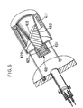
- FIG. 6 shows another embodiment of the source of this invention incorporating a crucible designed to utilize the reverse temperature gradient made possible by a thermal sink409 and an asymmetric crucible heater412.
- This "inverted" temperature gradient suppresses free convection within a liquid, effusing material.
- the sink can be cooled as in FIG. 4 or simply open to allow increased radiation loss as in FIG. 2a.
- Contaminants 431 more dense than the source material tend to segregate and accumulate at the cooler, closed crucible end.
- the crucible 403 has a special extension 423 projecting through the source base 420 into a thermal sink 409. This extension allows much greater cooling than the closed ends of crucibles of the other embodiments.
- FIG. 7 shows another embodiment of the source of this invention where the effusing material 540 may be located external to the source body.
- the remote location of source material is typical of gaseous source MBE (GSMBE) and chemical beam epitaxy (CBE).
- Gaseous sources such as arsine, phosphine and hydrogen and heated liquid sources such as the triethyl and trimethyl group III compounds are common in these processes. These materials are located remotely for safety (containment) and process control reasons.
- the materials are transported to sources typical of this invention which are positioned inside MBE systems. The transfer occurs as through the use of a pressurized gas or by mixing vapors with a "carrier” gas. Hydrogen is commonly used as a carrier gas.
- the sources are heated by heating elements located within the source body to prevent condensation in the source or to dissociate the effusing molecules. In some instances a catalytic reaction is involved.
- Another example is a "cracker" source composed of two separate heated sections.
- the effusing material solid or liquid
- the effusing material is contained in an external crucible immediately adjacent to the MBE system (usually referred to as the "sublimator”).
- the material is evaporated or sublimed through a connecting passage to the source body inside the MBE system (generally referred to as the "cracker").
- the passage provides thermal isolation between the two heated sections which can be at widely different temperatures.
- the "cracker" section serves to dissociate the effusing molecules and prevent material condensation as with the gas sources mentioned above.
- material from a "sublimator” or gas source enters through mounting flange 501 and continues through the source body 502 to the exit orifice 517.
- Heaters 512 and sinks 509 within the source body are configured as in the earlier heater embodiments in order to produce a specific temperature profile within the cracker section 503.
Landscapes
- Chemical & Material Sciences (AREA)
- Engineering & Computer Science (AREA)
- Materials Engineering (AREA)
- Metallurgy (AREA)
- Organic Chemistry (AREA)
- Chemical Kinetics & Catalysis (AREA)
- Mechanical Engineering (AREA)
- Crystallography & Structural Chemistry (AREA)
- Physical Deposition Of Substances That Are Components Of Semiconductor Devices (AREA)
- Crystals, And After-Treatments Of Crystals (AREA)
- Physical Vapour Deposition (AREA)
- Crucibles And Fluidized-Bed Furnaces (AREA)
Applications Claiming Priority (2)
| Application Number | Priority Date | Filing Date | Title |
|---|---|---|---|
| US07/916,381 US5253266A (en) | 1992-07-20 | 1992-07-20 | MBE effusion source with asymmetrical heaters |
| US916381 | 1992-07-20 |
Publications (2)
| Publication Number | Publication Date |
|---|---|
| EP0581496A2 true EP0581496A2 (de) | 1994-02-02 |
| EP0581496A3 EP0581496A3 (en) | 1994-06-22 |
Family
ID=25437175
Family Applications (1)
| Application Number | Title | Priority Date | Filing Date |
|---|---|---|---|
| EP19930305582 Withdrawn EP0581496A3 (en) | 1992-07-20 | 1993-07-15 | Molecular beam epitaxy (mbe) effusion source utilizing heaters to achieve temperature gradients |
Country Status (3)
| Country | Link |
|---|---|
| US (1) | US5253266A (de) |
| EP (1) | EP0581496A3 (de) |
| JP (1) | JPH06220619A (de) |
Cited By (3)
| Publication number | Priority date | Publication date | Assignee | Title |
|---|---|---|---|---|
| EP1662017A1 (de) * | 2004-11-20 | 2006-05-31 | Applied Films GmbH & Co. KG | Vorrichtung zum Verdampfen von Materialien |
| FR2878863A1 (fr) * | 2004-12-07 | 2006-06-09 | Addon Sa | Dispositif de depot sous vide a reservoir de recharge et procede de depot sous vide correspondant. |
| EP1752555A1 (de) * | 2005-07-28 | 2007-02-14 | Applied Materials GmbH & Co. KG | Verdampfervorrichtung |
Families Citing this family (27)
| Publication number | Priority date | Publication date | Assignee | Title |
|---|---|---|---|---|
| US5531034A (en) * | 1995-04-28 | 1996-07-02 | Mentz; James W. | Horizontal dryer having a screw conveyor and ring electrical heating elements |
| KR100270319B1 (ko) * | 1997-11-28 | 2000-10-16 | 정선종 | 에피택셜장치용 증발 도가니 |
| US20050147753A1 (en) * | 1999-10-22 | 2005-07-07 | Kurt J. Lesker Company | Material deposition system and a method for coating a substrate or thermally processing a material in a vacuum |
| US6830626B1 (en) * | 1999-10-22 | 2004-12-14 | Kurt J. Lesker Company | Method and apparatus for coating a substrate in a vacuum |
| US6541346B2 (en) | 2001-03-20 | 2003-04-01 | Roger J. Malik | Method and apparatus for a self-aligned heterojunction bipolar transistor using dielectric assisted metal liftoff process |
| WO2002103089A2 (en) * | 2002-08-16 | 2002-12-27 | Dca Instruments Oy | Heating of an effusion cell for molecular beam epitaxy |
| EP2369035B9 (de) * | 2003-08-04 | 2014-05-21 | LG Display Co., Ltd. | Verdampfungsquelle |
| JP4344631B2 (ja) * | 2004-03-02 | 2009-10-14 | 長州産業株式会社 | 有機物薄膜堆積用分子線源 |
| US20050229856A1 (en) * | 2004-04-20 | 2005-10-20 | Malik Roger J | Means and method for a liquid metal evaporation source with integral level sensor and external reservoir |
| US7402779B2 (en) * | 2004-07-13 | 2008-07-22 | Lucent Technologies Inc. | Effusion cell and method for use in molecular beam deposition |
| US8747554B2 (en) * | 2006-06-20 | 2014-06-10 | Momentive Performance Materials Inc. | Multi-piece ceramic crucible and method for making thereof |
| DE102007035166B4 (de) * | 2007-07-27 | 2010-07-29 | Createc Fischer & Co. Gmbh | Hochtemperatur-Verdampferzelle mit parallel geschalteten Heizbereichen, Verfahren zu deren Betrieb und deren Verwendung in Beschichtungsanlagen |
| WO2009060739A1 (ja) * | 2007-11-05 | 2009-05-14 | Ulvac, Inc. | 蒸着源、有機el素子の製造装置 |
| US20100159132A1 (en) * | 2008-12-18 | 2010-06-24 | Veeco Instruments, Inc. | Linear Deposition Source |
| US20100285218A1 (en) * | 2008-12-18 | 2010-11-11 | Veeco Instruments Inc. | Linear Deposition Source |
| WO2011065998A1 (en) * | 2008-12-18 | 2011-06-03 | Veeco Instruments Inc. | Linear deposition source |
| US20110104398A1 (en) * | 2009-10-29 | 2011-05-05 | General Electric Company | Method and system for depositing multiple materials on a substrate |
| KR101094299B1 (ko) * | 2009-12-17 | 2011-12-19 | 삼성모바일디스플레이주식회사 | 선형 증발원 및 이를 포함하는 증착 장치 |
| KR101182265B1 (ko) * | 2009-12-22 | 2012-09-12 | 삼성디스플레이 주식회사 | 증발원 및 이를 포함하는 증착 장치 |
| KR102052074B1 (ko) * | 2013-04-04 | 2019-12-05 | 삼성디스플레이 주식회사 | 증착 장치, 이를 이용한 박막 형성 방법 및 유기 발광 표시 장치 제조 방법 |
| CN104404450B (zh) * | 2014-10-28 | 2018-06-01 | 深圳市华星光电技术有限公司 | 用于升华型oled材料蒸镀的坩埚 |
| US10184168B2 (en) * | 2015-01-20 | 2019-01-22 | Kennametal Inc. | IMC evaporator boat-thermal insulation cartridge assembly |
| US20160281212A1 (en) * | 2015-03-24 | 2016-09-29 | Siva Power, Inc. | Thermal management of evaporation sources |
| JP6823954B2 (ja) * | 2016-07-08 | 2021-02-03 | 株式会社ジャパンディスプレイ | 成膜装置および成膜方法 |
| DE102019110950A1 (de) | 2019-04-29 | 2020-10-29 | Kennametal Inc. | Hartmetallzusammensetzungen und deren Anwendungen |
| KR102319130B1 (ko) * | 2020-03-11 | 2021-10-29 | 티오에스주식회사 | 가변 온도조절 장치를 구비한 금속-산화물 전자빔 증발원 |
| KR102582448B1 (ko) * | 2021-06-09 | 2023-09-22 | 선문대학교 산학협력단 | 열증착기용 히터 |
Family Cites Families (16)
| Publication number | Priority date | Publication date | Assignee | Title |
|---|---|---|---|---|
| US2665320A (en) * | 1949-09-22 | 1954-01-05 | Nat Res Corp | Metal vaporizing crucible |
| US2665225A (en) * | 1950-04-27 | 1954-01-05 | Nat Res Corp | Apparatus and process for coating by vapor deposition |
| US3634647A (en) * | 1967-07-14 | 1972-01-11 | Ernest Brock Dale Jr | Evaporation of multicomponent alloys |
| US3572672A (en) * | 1968-11-22 | 1971-03-30 | Rca Corp | Vacuum evaporation apparatus |
| JPS5418235B2 (de) * | 1972-12-29 | 1979-07-05 | ||
| US4021769A (en) * | 1976-03-18 | 1977-05-03 | Gte Sylvania Incorporated | Electrical heating element |
| JPS63155715A (ja) * | 1986-12-19 | 1988-06-28 | Omron Tateisi Electronics Co | 分子線セル |
| US4856457A (en) * | 1987-02-20 | 1989-08-15 | Hughes Aircraft Company | Cluster source for nonvolatile species, having independent temperature control |
| JP2771215B2 (ja) * | 1989-02-03 | 1998-07-02 | 株式会社日立製作所 | 分子線源用るつぼおよびそれを用いた分子線エピタキシャル成長膜の形成方法 |
| GB2230792A (en) * | 1989-04-21 | 1990-10-31 | Secr Defence | Multiple source physical vapour deposition. |
| US5034604A (en) * | 1989-08-29 | 1991-07-23 | Board Of Regents, The University Of Texas System | Refractory effusion cell to generate a reproducible, uniform and ultra-pure molecular beam of elemental molecules, utilizing reduced thermal gradient filament construction |
| US5041719A (en) * | 1990-06-01 | 1991-08-20 | General Electric Company | Two-zone electrical furnace for molecular beam epitaxial apparatus |
| WO1992003588A1 (en) * | 1990-08-24 | 1992-03-05 | Dca Instruments Oy | Heater for an effusion cell |
| US5142117A (en) * | 1990-11-20 | 1992-08-25 | Motorola, Inc. | Proximity heater for an ultrasonic bonding tool |
| JPH04198090A (ja) * | 1990-11-28 | 1992-07-17 | Matsushita Electric Ind Co Ltd | 分子線セル |
| FR2670219B1 (fr) * | 1990-12-07 | 1993-03-19 | Europ Propulsion | Appareil et creuset pour depot en phase vapeur. |
-
1992
- 1992-07-20 US US07/916,381 patent/US5253266A/en not_active Expired - Lifetime
-
1993
- 1993-07-15 EP EP19930305582 patent/EP0581496A3/en not_active Withdrawn
- 1993-07-20 JP JP5199923A patent/JPH06220619A/ja active Pending
Cited By (4)
| Publication number | Priority date | Publication date | Assignee | Title |
|---|---|---|---|---|
| EP1662017A1 (de) * | 2004-11-20 | 2006-05-31 | Applied Films GmbH & Co. KG | Vorrichtung zum Verdampfen von Materialien |
| FR2878863A1 (fr) * | 2004-12-07 | 2006-06-09 | Addon Sa | Dispositif de depot sous vide a reservoir de recharge et procede de depot sous vide correspondant. |
| WO2006061517A1 (fr) * | 2004-12-07 | 2006-06-15 | Addon | Dispositif de depot sous vide a reservoir de recharge et procédé de dépôt sous vide correspondant |
| EP1752555A1 (de) * | 2005-07-28 | 2007-02-14 | Applied Materials GmbH & Co. KG | Verdampfervorrichtung |
Also Published As
| Publication number | Publication date |
|---|---|
| JPH06220619A (ja) | 1994-08-09 |
| EP0581496A3 (en) | 1994-06-22 |
| US5253266A (en) | 1993-10-12 |
Similar Documents
| Publication | Publication Date | Title |
|---|---|---|
| US5253266A (en) | MBE effusion source with asymmetrical heaters | |
| US5041719A (en) | Two-zone electrical furnace for molecular beam epitaxial apparatus | |
| US9062369B2 (en) | Deposition of high vapor pressure materials | |
| SU1433420A3 (ru) | Холодный тигель | |
| US5683507A (en) | Apparatus for growing large silicon carbide single crystals | |
| US6866714B2 (en) | Large size semiconductor crystal with low dislocation density | |
| RU2059025C1 (ru) | Тигель из нитрида бора и способ его получения | |
| US11661671B2 (en) | Technique for controlling temperature uniformity in crystal growth apparatus | |
| US4597949A (en) | Apparatus for growing crystals | |
| EP3760765B1 (de) | System zur horizontalen züchtung von hochqualitativen halbleitereinkristallen und verfahren zur herstellung davon | |
| CN115821372A (zh) | 晶体生长装置 | |
| JP4052678B2 (ja) | 大形炭化珪素単結晶成長装置 | |
| US3051555A (en) | Crucible for melting silicon of highest purity and method of making it | |
| US5156815A (en) | Sublimating and cracking apparatus | |
| JP2002530266A (ja) | 基板上に結晶成長させる方法 | |
| US3781152A (en) | Apparatus for precipitating a layer of semiconductor material from a gaseous compound of the semiconductor material | |
| US20250327210A1 (en) | SiC POLYCRYSTAL MANUFACTURING METHOD | |
| US20080282983A1 (en) | High Temperature Vacuum Evaporation Apparatus | |
| KR20030038268A (ko) | 유기물 진공증착용 도가니형 증발원 | |
| JP2013075789A (ja) | 化合物半導体単結晶の製造装置および製造方法 | |
| KR20210001300A (ko) | 실리콘카바이드 단결정의 제조 장치 | |
| JP7358944B2 (ja) | SiC単結晶成長用伝熱部材、SiC単結晶成長用坩堝、SiC単結晶の製造方法 | |
| JP2733535B2 (ja) | 半導体薄膜気相成長装置 | |
| EP4414480A1 (de) | System zur herstellung eines hochqualitativen halbleitereinkristalls und herstellungsverfahren dafür | |
| MXPA06003634A (es) | Horno de campo magnetico y metodo de uso del mismo para fabricar sustratos semiconductores. |
Legal Events
| Date | Code | Title | Description |
|---|---|---|---|
| PUAI | Public reference made under article 153(3) epc to a published international application that has entered the european phase |
Free format text: ORIGINAL CODE: 0009012 |
|
| AK | Designated contracting states |
Kind code of ref document: A2 Designated state(s): CH DE FR GB IT LI NL SE |
|
| PUAL | Search report despatched |
Free format text: ORIGINAL CODE: 0009013 |
|
| AK | Designated contracting states |
Kind code of ref document: A3 Designated state(s): CH DE FR GB IT LI NL SE |
|
| STAA | Information on the status of an ep patent application or granted ep patent |
Free format text: STATUS: THE APPLICATION IS DEEMED TO BE WITHDRAWN |
|
| 18D | Application deemed to be withdrawn |
Effective date: 19941223 |