EP0581592A1 - Siège de véhicule comportant des moyens pour freiner le mouvement en avant - Google Patents
Siège de véhicule comportant des moyens pour freiner le mouvement en avant Download PDFInfo
- Publication number
- EP0581592A1 EP0581592A1 EP93305996A EP93305996A EP0581592A1 EP 0581592 A1 EP0581592 A1 EP 0581592A1 EP 93305996 A EP93305996 A EP 93305996A EP 93305996 A EP93305996 A EP 93305996A EP 0581592 A1 EP0581592 A1 EP 0581592A1
- Authority
- EP
- European Patent Office
- Prior art keywords
- backrest part
- seat
- braking means
- vehicle seat
- passenger
- Prior art date
- Legal status (The legal status is an assumption and is not a legal conclusion. Google has not performed a legal analysis and makes no representation as to the accuracy of the status listed.)
- Withdrawn
Links
- 210000003127 knee Anatomy 0.000 claims abstract description 18
- 230000002159 abnormal effect Effects 0.000 claims description 3
- 208000027418 Wounds and injury Diseases 0.000 description 3
- 230000006378 damage Effects 0.000 description 3
- 208000014674 injury Diseases 0.000 description 3
- 230000001133 acceleration Effects 0.000 description 2
- 230000000694 effects Effects 0.000 description 2
- 206010019196 Head injury Diseases 0.000 description 1
- 230000006835 compression Effects 0.000 description 1
- 238000007906 compression Methods 0.000 description 1
- 238000010276 construction Methods 0.000 description 1
- 230000004048 modification Effects 0.000 description 1
- 238000012986 modification Methods 0.000 description 1
Images

Classifications
-
- B—PERFORMING OPERATIONS; TRANSPORTING
- B60—VEHICLES IN GENERAL
- B60N—SEATS SPECIALLY ADAPTED FOR VEHICLES; VEHICLE PASSENGER ACCOMMODATION NOT OTHERWISE PROVIDED FOR
- B60N2/00—Seats specially adapted for vehicles; Arrangement or mounting of seats in vehicles
- B60N2/24—Seats specially adapted for vehicles; Arrangement or mounting of seats in vehicles for particular purposes or particular vehicles
- B60N2/42—Seats specially adapted for vehicles; Arrangement or mounting of seats in vehicles for particular purposes or particular vehicles the seat constructed to protect the occupant from the effect of abnormal g-forces, e.g. crash or safety seats
- B60N2/433—Safety locks for back-rests, e.g. with locking bars activated by inertia
-
- B—PERFORMING OPERATIONS; TRANSPORTING
- B60—VEHICLES IN GENERAL
- B60N—SEATS SPECIALLY ADAPTED FOR VEHICLES; VEHICLE PASSENGER ACCOMMODATION NOT OTHERWISE PROVIDED FOR
- B60N2/00—Seats specially adapted for vehicles; Arrangement or mounting of seats in vehicles
- B60N2/24—Seats specially adapted for vehicles; Arrangement or mounting of seats in vehicles for particular purposes or particular vehicles
- B60N2/42—Seats specially adapted for vehicles; Arrangement or mounting of seats in vehicles for particular purposes or particular vehicles the seat constructed to protect the occupant from the effect of abnormal g-forces, e.g. crash or safety seats
- B60N2/4207—Seats specially adapted for vehicles; Arrangement or mounting of seats in vehicles for particular purposes or particular vehicles the seat constructed to protect the occupant from the effect of abnormal g-forces, e.g. crash or safety seats characterised by the direction of the g-forces
- B60N2/4214—Seats specially adapted for vehicles; Arrangement or mounting of seats in vehicles for particular purposes or particular vehicles the seat constructed to protect the occupant from the effect of abnormal g-forces, e.g. crash or safety seats characterised by the direction of the g-forces longitudinal
- B60N2/4221—Seats specially adapted for vehicles; Arrangement or mounting of seats in vehicles for particular purposes or particular vehicles the seat constructed to protect the occupant from the effect of abnormal g-forces, e.g. crash or safety seats characterised by the direction of the g-forces longitudinal due to impact coming from the front
-
- B—PERFORMING OPERATIONS; TRANSPORTING
- B60—VEHICLES IN GENERAL
- B60N—SEATS SPECIALLY ADAPTED FOR VEHICLES; VEHICLE PASSENGER ACCOMMODATION NOT OTHERWISE PROVIDED FOR
- B60N2/00—Seats specially adapted for vehicles; Arrangement or mounting of seats in vehicles
- B60N2/24—Seats specially adapted for vehicles; Arrangement or mounting of seats in vehicles for particular purposes or particular vehicles
- B60N2/42—Seats specially adapted for vehicles; Arrangement or mounting of seats in vehicles for particular purposes or particular vehicles the seat constructed to protect the occupant from the effect of abnormal g-forces, e.g. crash or safety seats
- B60N2/427—Seats or parts thereof displaced during a crash
- B60N2/42727—Seats or parts thereof displaced during a crash involving substantially rigid displacement
- B60N2/42736—Seats or parts thereof displaced during a crash involving substantially rigid displacement of the whole seat
-
- B—PERFORMING OPERATIONS; TRANSPORTING
- B60—VEHICLES IN GENERAL
- B60N—SEATS SPECIALLY ADAPTED FOR VEHICLES; VEHICLE PASSENGER ACCOMMODATION NOT OTHERWISE PROVIDED FOR
- B60N2/00—Seats specially adapted for vehicles; Arrangement or mounting of seats in vehicles
- B60N2/24—Seats specially adapted for vehicles; Arrangement or mounting of seats in vehicles for particular purposes or particular vehicles
- B60N2/42—Seats specially adapted for vehicles; Arrangement or mounting of seats in vehicles for particular purposes or particular vehicles the seat constructed to protect the occupant from the effect of abnormal g-forces, e.g. crash or safety seats
- B60N2/427—Seats or parts thereof displaced during a crash
- B60N2/42727—Seats or parts thereof displaced during a crash involving substantially rigid displacement
- B60N2/42745—Seats or parts thereof displaced during a crash involving substantially rigid displacement of the back-rest
-
- B—PERFORMING OPERATIONS; TRANSPORTING
- B60—VEHICLES IN GENERAL
- B60N—SEATS SPECIALLY ADAPTED FOR VEHICLES; VEHICLE PASSENGER ACCOMMODATION NOT OTHERWISE PROVIDED FOR
- B60N2/00—Seats specially adapted for vehicles; Arrangement or mounting of seats in vehicles
- B60N2/24—Seats specially adapted for vehicles; Arrangement or mounting of seats in vehicles for particular purposes or particular vehicles
- B60N2/42—Seats specially adapted for vehicles; Arrangement or mounting of seats in vehicles for particular purposes or particular vehicles the seat constructed to protect the occupant from the effect of abnormal g-forces, e.g. crash or safety seats
- B60N2/427—Seats or parts thereof displaced during a crash
- B60N2/42772—Seats or parts thereof displaced during a crash characterised by the triggering system
- B60N2/42781—Seats or parts thereof displaced during a crash characterised by the triggering system mechanical triggering
Definitions
- Vehicle seats which are arranged in forwardly- facing rows are commonly made so that each backrest can be folded forwardly about a hinge joint adjacent to the seat bottom. This is to facilitate transport of seating units and it has also been thought to contribute to the safety of passengers since in the event of a crash a passenger was thought likely to be thrown forwardly so that his head would strike the backrest of the seat in front. It was thought that if the backrest folded (or “broke”) forwardly about the hinge joint when struck by the passenger's head that would reduce the impact.
- Seats for use in passenger aircraft are commonly adjusted so that a backrest will fold (or "break") forwardly when a load equivalent to about 14 kg. applied to the top of the backrest is applied in a forward direction.
- a vehicle seat comprising a frame for mounting in a vehicle, a seat bottom part mounted on the frame and a backrest part hingedly connected to the frame adjacent to the seat bottom so as to break forwardly about the hinged connection from a normal position is characterized by braking means for preventing forward movement of the backrest part about the hinged connection under forces equivalent to less than a predetermined maximum forward force applied to the top of the backrest part but to permit forward movement of the backrest part about the hinged connection under greater forces against a reaction provided by the braking means.
- a "normal" position of the backrest part is meant a substantially upright position like an ordinary chair backrest or a reclined position inclined rearwardly from such an upright position, such as is commonly provided for in vehicle seats.
- the predetermined maximum forward force is calculated to be substantially in excess of a reference force which would produce a moment about the hinged connection equal to the maximum moment likely to be produced by the knees and/or hands of a passenger making initial contact with the backrest part when a crash occurs, as described above. Typically it may be twice or three times that reference force.
- the braking means may be combined with recline control means such as is commonly provided in vehicle seats to enable a passenger in a seat to adjust the angular position of the backrest part relative to the seat bottom part about the hinged connection.
- the braking means is arranged to provide a progressively increasing reaction as the permitted forward movement of the backrest part proceeds. Then the passenger's head will be decelerated progressively once it has struck the backrest part, further reducing the risk of serious injury.
- a vehicle seat comprising a frame for mounting in a vehicle, a seat bottom part mounted on the frame and a backrest part hingedly connected to the frame adjacent to the seat bottom so as to break forwardly about the hinged connection from a normal position
- braking means for preventing forward movement of the backrest part about the hinged connection under forces equivalent to less than a predetermined maximum forward force applied to the top of the backrest part but to permit forward movement of the backrest part about the hinged connection under greater forces against a reaction provided by the braking means which increases progressively as the permitted forward movement of the backrest part proceeds
- the said braking means being combined with the usual recline control means which enables a passenger in the seat to adjust the angular position of the backrest part relative to the seat bottom part about the hinged connection, and a locking device to prevent any further forward movement of the backrest part after it has been returned to its normal position after permitted forward movement.
- the backrest part may be and preferably is so constructed that no significant force may be applied to it in a forward direction in the region which will be immediately in front of the knees of a passenger properly seated in a seat immediately behind. That may be achieved most simply by providing an aperture in that region so that in the event of very rapid deceleration such as occurs in a crash the knees of a passenger occupying a seat immediately behind do not contact the backrest part, but pass into the aperture and strike the rear of the seat bottom, which may be suitably padded to reduce the risk of injury to the knees.
- an aperture may be provided only in the inner structure of the backrest part and be covered, particularly on the front and/or back of the backrest part, by a light surface element, capable of deformation or fracture under impact from the knees of a passenger to enable them to pass through the aperture without applying significant force to the backrest part.
- the seat may include a connecting device between the braking means and the backrest part, either capable of disconnection when required or normally disconnected so that the backrest part may fold forwardly about the said connection in the usual way, but operative automatically under abnormal forward deceleration to connect the braking means to the backrest part.
- the braking means is preferably arranged so as not to resist significantly the return of the backrest part to its normal substantially upright position after it has broken forwardly under a force equivalent to a force applied to its top greater than the said predetermined maximum forward force and may include a locking device to prevent any further forward movement of the backrest part after it has been returned to that normal position. This may be of particular importance for a seat which is located alongside an emergency escape door or window which might be obstructed by the forwardly-folded backrest part.
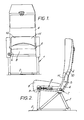
- the seat shown in Figures 1 and 2 comprises a frame 1 designed to be secured to the floor 2 of a vehicle, such as a passenger aircraft, supporting a seat bottom part 3 which is upholstered as usual and a backrest part 4, hingedly connected to the frame 1 at each side by aligned pivot pins 5.
- An extension piece 6 is secured to one side of the backrest part 4 and extends beyond the pivot pin 5 on that side.
- the end of the extension is pivotally connected at 7 to the end of a braking device 8, the other end of which is adjust- ably connected to a lug 9 which is rotatably mounted on the frame 1.
- An aperture 10 is formed in the lower portion of the backrest part 4 which will be directly in front of the knees of a passenger in a seat immediately behind.
- the aperture 10 is covered by a light surface element 11, continuous with the front surface of the remainder of the backrest part, capable of defonnation, detachment orfracture under impact from the knees of a passenger to enable them to pass through the aperture without applying significant force to the backrest part.
- the braking device 8 includes the usual pneumatic or hydraulic recline control device comprising telescopic tubular parts 12 and 13 for controlling reclining movement of the backrest part 4 relative to the frame 1.
- a valve control member 14 at the end of the part 12 can be operated by a passenger occupying the seat to permit relative longitudinal movement between the parts 12 and 13.
- the passenger operates the valve control member 14 and applies a rearward force against the backrest part with his back.
- the part 13 slides longitudinally over the part 12 until the control member 14 is released, whereupon the parts 12 and 13 are locked in their new relative position, holding the backrest part 4 in the reclined position chosen by the passenger.
- a compression spring 15 surrounds the parts 12 and 13, engaging abutments 16 and 17 to urge the part 13 longitudinally rearwardly with respect to the part 12 which is fixed to the frame 1. If the passenger operates the control member 14 without applying a rearward force to the backrest part, the spring will cause the part 13 to move rearwardly with respect to the part 12, causing the backrest part 4 to rotate about the pivot pins 5 towards an upright position.
- the construction and operation of these parts is well known and will not be described further.
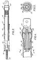
- the end of the part 13 enters a tube 18 and is connected by screw threads to a member having a ball-like head 19 which is of diameter somewhat larg- erthan the internal diameter of the tube 18 and is accommodated in an enlarged part 20 at the end of the tube 18.
- the enlarged part 20 is clenched over a clevis part 21 by which the braking device 8 is connected to the end 7 of the extension 6 (see Figure 2).
- the material, wall thickness and diameter of the tube 18 and the diameter of the ball-like head 19 are selected so that the force necessary to expand the tube and draw it over the ball-like head produces a moment about the pivot pins 5 equal to the said predetermined maximum forward force applied to the top of the backrest.
- the wall thickness may be varied to produce a varying braking force as forward movement of the backrest part4 proceeds. For example, to provide a gradually increasing braking force, the wall thickness of the tube 18 may be increased progressively along its length from the enlarged part 20.
- the backrest part4 may be moved back to its upright position by applying a rearward force to its upper end, causing the ball-like head 19 to move towards the clevis part 21.
- the braking device 8 provides no significant resistance to such return movement.
- the backrest part could then be folded forwardly again without significant resistance and may tend to remain in the forward position. That may be unsatisfactory, particularly for a seat adjacent to an emergency exit from a vehicle, since it might impede access to the exit.
- Figures 4 and 5 show a modification of the braking device 8 to avoid this.
- the member having the ball-like head 19 is replaced by a tubular member 22 having a ball-like head 19 and a split tubular locking device 23 is secured to the clevis member 21 and extends coaxially through the tubular member 22.
- the tubular locking device is split throughout the major part of its length on two perpendicular diameters (see Figure 5) to provide four prongs 24 which are just longer than the tubular member 22 and somewhat enlarged at their ends to provide locking parts 25.
- the prongs are biassed outwardly from the position shown so that their locking parts 25 lie on a diameter greater than the internal diameter of the tubular member 22, but when assembled they are held in to a smaller diameter by a split spring circlip 26, of normal diameter greater than that internal diameter, fitted within the tubular member 22 near its end remote from the clevis member 21.
- the outer surfaces of the locking parts 25 are chamfered as shown at 27 for a purpose to be described.
- the ball-like head of the tubular member 22 can move back into the tube 18 without significant resistance.
- their chamfered outer surfaces 27 will cause them to be compressed radially so that they re-enter the ball-like head.
- the splitcir- clip having expanded, will be struck by the end of the ball-like head and be driven along the split tubular locking device 23 into a recess 28 provided in the end of the clevis member 21 to receive it.
- the prongs 24, no longer being constrained by the circlip 26, are free to expand as soon as their enlarged ends 25 project from the end of the tubular member 22 and they then lock behind its end, so locking the tubular member 22 to the clevis member 21 and preventing the backrest part 4 being moved forwardly again.
- the invention is not limited to the use of braking devices as shown in Figures 3, 4 and 5. Many other forms of braking device could be used.
- the braking device is required only in the event of a crash in which forward motion of the vehicle is rapidly decelerated, such as an aircraft crash, but its presence in the arrangement shown in Figures 1 and 2 prevents the usual provision for the backrest part 4 to break forwardly about the pivot pins 5 except under forces greater than a force equivalent to the pre-determined maximum forward force. That may be undesirable and Figures 6 and 7 show an inertia-operated connecting device between the braking device and the backrest part 4. In place of the extension piece 6 at one side of the backrest part 4 as shown in Figures I and 2 a separate element 29 is mounted on the pivot pin 5 at one side, to rotate about the pivot pin independently of the backrest part 4.
- the nut may be adjusted to allow movement when a predetermined force, say 14 kg., is applied to the top of the backrest part.
- the end of the backest part 4 is formed with a hook 33 to engage a pin 34 secured to the element 29 so that reclining movement of the backrest part will be controlled by the usual pneumatic or hydraulic device as previously described,
- the hook 33 also has a reverse hook recess 35.
- a pivotal locking element 36 is connected to the element 29 so as to swing freely about a pin 37.
- the locking element illustrated is designed for inertia operation and has a nose 38, positioned to be just clear of the reverse hook recess 35 when the locking element hangs normally from its pivot pin 37, but movable to enter the reverse hook recess and prevent forward rotation of the backrest part 4 about the pivot pin 5 without simultaneously rotating the element 29.
- the end of the locking element 36 is weighted at 39 so that in the event of rapid deceleration of the vehicle it is automatically swung forwardly by inertia to engage the nose 38 in the reverse hook recess 35.
- a locking element may be spring-urged into a position in which its nose will engage the reverse hook recess and manual means may be provided to release it when it is desired to break the backrest part 4 forwardly.
Landscapes
- Engineering & Computer Science (AREA)
- Aviation & Aerospace Engineering (AREA)
- Transportation (AREA)
- Mechanical Engineering (AREA)
- Chairs For Special Purposes, Such As Reclining Chairs (AREA)
- Seats For Vehicles (AREA)
- Fluid-Damping Devices (AREA)
- Chair Legs, Seat Parts, And Backrests (AREA)
Applications Claiming Priority (2)
| Application Number | Priority Date | Filing Date | Title |
|---|---|---|---|
| GB9216245 | 1992-07-30 | ||
| GB9216245A GB2269986B (en) | 1992-07-30 | 1992-07-30 | Vehicle seats |
Publications (1)
| Publication Number | Publication Date |
|---|---|
| EP0581592A1 true EP0581592A1 (fr) | 1994-02-02 |
Family
ID=10719570
Family Applications (1)
| Application Number | Title | Priority Date | Filing Date |
|---|---|---|---|
| EP93305996A Withdrawn EP0581592A1 (fr) | 1992-07-30 | 1993-07-29 | Siège de véhicule comportant des moyens pour freiner le mouvement en avant |
Country Status (6)
| Country | Link |
|---|---|
| EP (1) | EP0581592A1 (fr) |
| JP (1) | JPH06154059A (fr) |
| CN (2) | CN1087312A (fr) |
| AU (2) | AU4430793A (fr) |
| GB (2) | GB2269986B (fr) |
| HK (1) | HK1004760A1 (fr) |
Cited By (9)
| Publication number | Priority date | Publication date | Assignee | Title |
|---|---|---|---|---|
| WO1996016834A1 (fr) * | 1994-11-25 | 1996-06-06 | Rasenberg Johannes Theodorus M | Siege et vehicule equipe de ce siege |
| WO1997029923A1 (fr) * | 1996-02-16 | 1997-08-21 | Renault | Agencement d'un dispositif de limitation de l'effort de retenue d'un occupant dans un siege de vehicule automobile muni d'une ceinture de securite |
| FR2772688A1 (fr) * | 1997-12-19 | 1999-06-25 | Cesa | Dispositif de blocage en cas de choc de deux organes deplacables l'un par rapport a l'autre et siege muni de ce dispositif |
| EP0945302A1 (fr) * | 1998-03-27 | 1999-09-29 | Societe Industrielle Et Commerciale De Materiel Aeronautique (Sicma) Societe Anonyme | Dispositif d'évacuation de masse, structure de siège, siège et véhicle équipé de ce dispositif |
| US7837259B2 (en) * | 2005-05-13 | 2010-11-23 | Recaro Aircraft Seating Gmbh & Co. Kg | Seat, in particular air passenger seat |
| FR3001711A1 (fr) * | 2013-02-07 | 2014-08-08 | Expliseat | Siege de vehicule comportant une zone deformable en cas de choc |
| WO2017044169A1 (fr) * | 2015-09-11 | 2017-03-16 | Zodiac Seats Us Llc | Mécanisme de retournement de dossier de siège consolidé |
| CN114750717A (zh) * | 2022-03-28 | 2022-07-15 | 东风柳州汽车有限公司 | 车辆座椅靠背调节方法、装置、设备及存储介质 |
| US20240116415A1 (en) * | 2022-10-11 | 2024-04-11 | B/E Aerospace, Inc. | Device for constraining actuator motion during a dynamic event |
Families Citing this family (8)
| Publication number | Priority date | Publication date | Assignee | Title |
|---|---|---|---|---|
| DE19647649A1 (de) * | 1996-11-18 | 1998-05-20 | Dsd Dr Steffan Datentechnik Gm | Fahrzeugsitzanordnung mit einem Sitzteil und einer Lehne |
| DE102005012899B3 (de) * | 2005-03-21 | 2006-06-01 | Keiper Gmbh & Co.Kg | Federsystem in einem Fahrzeugsitz |
| JP4680215B2 (ja) * | 2007-02-27 | 2011-05-11 | 本田技研工業株式会社 | 内燃機関の動弁装置 |
| EP2692575B1 (fr) * | 2011-03-31 | 2018-10-31 | TS Tech Co., Ltd. | Siège de véhicule |
| DE102011055860A1 (de) | 2011-11-30 | 2013-06-06 | Brose Fahrzeugteile Gmbh & Co. Kommanditgesellschaft, Coburg | Fahrzeugsitz mit Deformationseinrichtung |
| CN105411229A (zh) * | 2016-01-08 | 2016-03-23 | 浙江国华家具有限公司 | 一种休闲办公椅 |
| FR3062610B1 (fr) * | 2017-02-08 | 2019-04-19 | Expliseat | Siege pour vehicule avec dossier basculant |
| DE102021124418A1 (de) | 2021-09-21 | 2023-03-23 | Recaro Aircraft Seating Gmbh & Co. Kg | Flugzeugsitzvorrichtung |
Citations (6)
| Publication number | Priority date | Publication date | Assignee | Title |
|---|---|---|---|---|
| FR2156938A5 (fr) * | 1971-10-11 | 1973-06-01 | Peugeot & Renault | |
| FR2162940A5 (fr) * | 1971-11-23 | 1973-07-20 | Gen Motors Corp | |
| US3832002A (en) * | 1973-03-21 | 1974-08-27 | Budd Co | Automotive restraint system |
| FR2226299A1 (fr) * | 1973-04-20 | 1974-11-15 | Saito Takeji | |
| JPS60121148A (ja) * | 1983-12-03 | 1985-06-28 | Giichi Sugimoto | 自動車用衝撃吸収リクライニングシ−ト |
| US5133587A (en) * | 1989-11-20 | 1992-07-28 | Hadden Jr James R | Seat |
Family Cites Families (9)
| Publication number | Priority date | Publication date | Assignee | Title |
|---|---|---|---|---|
| DE2360165C2 (de) * | 1973-12-03 | 1982-11-25 | Drabert Söhne Minden (Westf.), 4950 Minden | Sitzmöbel mit schwenkbarer Rückenlehne |
| US3997133A (en) * | 1975-07-30 | 1976-12-14 | Textron, Inc. | Crash attenuation landing gear |
| DE2755565C3 (de) * | 1977-12-13 | 1980-07-24 | Erhart Dr. 4500 Osnabrueck Wilisch | Prellbock für Schienenfahrzeuge |
| US4394047A (en) * | 1981-06-01 | 1983-07-19 | Uop Inc. | Seat back mounting system |
| FR2511103A1 (fr) * | 1981-08-10 | 1983-02-11 | Aerospatiale | Composants munis d'un dispositif d'absorption d'energie par deformation plastique et/ou de limitation d'effort, et trains d'atterrissage d'aerodynes equipes de tels composants |
| FR2537542B1 (fr) * | 1982-12-08 | 1985-11-15 | Aerospatiale | Trains d'atterissage a patins equipes de composants munis d'un dispositif d'absorption d'energie par deformation plastique et/ou de limitation d'effort, et composants de ce type |
| FR2554695B1 (fr) * | 1983-11-16 | 1986-03-28 | Peugeot Cycles | Mecanisme d'inclinaison pour siege, et notamment pour siege d'automobile |
| KR860001705Y1 (ko) * | 1984-05-26 | 1986-07-31 | 한명자 | 리크라이너 |
| US5320308A (en) * | 1991-12-04 | 1994-06-14 | Weber Aircraft, Inc. | Seatback breakover device |
-
1992
- 1992-07-30 GB GB9216245A patent/GB2269986B/en not_active Expired - Fee Related
-
1993
- 1993-07-29 CN CN93117096A patent/CN1087312A/zh active Pending
- 1993-07-29 EP EP93305996A patent/EP0581592A1/fr not_active Withdrawn
- 1993-07-29 AU AU44307/93A patent/AU4430793A/en not_active Abandoned
- 1993-07-29 CN CN93117095A patent/CN1093324A/zh active Pending
- 1993-07-29 AU AU44308/93A patent/AU4430893A/en not_active Abandoned
- 1993-07-30 JP JP5208776A patent/JPH06154059A/ja active Pending
- 1993-07-30 GB GB9315816A patent/GB2270734B/en not_active Expired - Fee Related
-
1998
- 1998-05-06 HK HK98103870A patent/HK1004760A1/xx not_active IP Right Cessation
Patent Citations (6)
| Publication number | Priority date | Publication date | Assignee | Title |
|---|---|---|---|---|
| FR2156938A5 (fr) * | 1971-10-11 | 1973-06-01 | Peugeot & Renault | |
| FR2162940A5 (fr) * | 1971-11-23 | 1973-07-20 | Gen Motors Corp | |
| US3832002A (en) * | 1973-03-21 | 1974-08-27 | Budd Co | Automotive restraint system |
| FR2226299A1 (fr) * | 1973-04-20 | 1974-11-15 | Saito Takeji | |
| JPS60121148A (ja) * | 1983-12-03 | 1985-06-28 | Giichi Sugimoto | 自動車用衝撃吸収リクライニングシ−ト |
| US5133587A (en) * | 1989-11-20 | 1992-07-28 | Hadden Jr James R | Seat |
Non-Patent Citations (1)
| Title |
|---|
| PATENT ABSTRACTS OF JAPAN * |
Cited By (18)
| Publication number | Priority date | Publication date | Assignee | Title |
|---|---|---|---|---|
| WO1996016834A1 (fr) * | 1994-11-25 | 1996-06-06 | Rasenberg Johannes Theodorus M | Siege et vehicule equipe de ce siege |
| NL9401985A (nl) * | 1994-11-25 | 1996-07-01 | Johannes Theodorus Marie Rasen | Stoel en daarmee uitgerust voertuig. |
| WO1997029923A1 (fr) * | 1996-02-16 | 1997-08-21 | Renault | Agencement d'un dispositif de limitation de l'effort de retenue d'un occupant dans un siege de vehicule automobile muni d'une ceinture de securite |
| FR2744961A1 (fr) * | 1996-02-16 | 1997-08-22 | Renault | Agencement d'un dispositif de limitation de l'effort de retenue d'un occupant dans un siege de vehicule automobile muni d'une ceinture de securite |
| FR2772688A1 (fr) * | 1997-12-19 | 1999-06-25 | Cesa | Dispositif de blocage en cas de choc de deux organes deplacables l'un par rapport a l'autre et siege muni de ce dispositif |
| EP0945302A1 (fr) * | 1998-03-27 | 1999-09-29 | Societe Industrielle Et Commerciale De Materiel Aeronautique (Sicma) Societe Anonyme | Dispositif d'évacuation de masse, structure de siège, siège et véhicle équipé de ce dispositif |
| FR2776589A1 (fr) * | 1998-03-27 | 1999-10-01 | Sicma Aero Seat | Dispositif d'evacuation de masse, structure de siege, siege et vehicule equipe de ce dispositif |
| US7837259B2 (en) * | 2005-05-13 | 2010-11-23 | Recaro Aircraft Seating Gmbh & Co. Kg | Seat, in particular air passenger seat |
| FR3001711A1 (fr) * | 2013-02-07 | 2014-08-08 | Expliseat | Siege de vehicule comportant une zone deformable en cas de choc |
| WO2014122173A1 (fr) * | 2013-02-07 | 2014-08-14 | Expliseat | Siege de vehicule comportant une zone deformable en cas de choc |
| US9764843B2 (en) | 2013-02-07 | 2017-09-19 | Expliseat | Vehicle seat comprising an area that is deformable in the event of an impact |
| WO2017044169A1 (fr) * | 2015-09-11 | 2017-03-16 | Zodiac Seats Us Llc | Mécanisme de retournement de dossier de siège consolidé |
| US10279913B2 (en) | 2015-09-11 | 2019-05-07 | Safran Seats Usa Llc | Consolidated seat back breakover mechanism |
| US10384783B2 (en) | 2015-09-11 | 2019-08-20 | Safran Seats Usa Llc | Inertial breakover mechanism |
| US10773805B2 (en) | 2015-09-11 | 2020-09-15 | Safran Seats Usa Llc | Consolidated seat back breakover mechanism |
| CN114750717A (zh) * | 2022-03-28 | 2022-07-15 | 东风柳州汽车有限公司 | 车辆座椅靠背调节方法、装置、设备及存储介质 |
| US20240116415A1 (en) * | 2022-10-11 | 2024-04-11 | B/E Aerospace, Inc. | Device for constraining actuator motion during a dynamic event |
| US12384280B2 (en) * | 2022-10-11 | 2025-08-12 | B/E Aerospace, Inc. | Device for constraining actuator motion during a dynamic event |
Also Published As
| Publication number | Publication date |
|---|---|
| CN1093324A (zh) | 1994-10-12 |
| GB2269986B (en) | 1997-03-19 |
| GB2270734B (en) | 1995-07-26 |
| AU4430793A (en) | 1994-02-03 |
| GB2270734A (en) | 1994-03-23 |
| JPH06154059A (ja) | 1994-06-03 |
| HK1004760A1 (en) | 1998-12-04 |
| GB9315816D0 (en) | 1993-09-15 |
| CN1087312A (zh) | 1994-06-01 |
| GB2269986A (en) | 1994-03-02 |
| AU4430893A (en) | 1994-02-03 |
| GB9216245D0 (en) | 1992-09-09 |
Similar Documents
| Publication | Publication Date | Title |
|---|---|---|
| US5454622A (en) | Vehicle seats | |
| GB2269986A (en) | Vehicle seats | |
| JP2843801B2 (ja) | 車両シート | |
| US8191830B2 (en) | Aircraft ejection seat with moveable headrest | |
| JP3516624B2 (ja) | 可動安全棒を有する車両座席 | |
| US5320308A (en) | Seatback breakover device | |
| US7699265B2 (en) | Aircraft ejection seat with movable headrest | |
| JP2856550B2 (ja) | 自動車内の安全装置 | |
| US11364825B2 (en) | Vehicle seat arrangement | |
| KR100264468B1 (ko) | 차량용 좌석 | |
| EP0847917B1 (fr) | Siège comportant un dispositif pour réduire un impact de la tête | |
| CN109292096B (zh) | 用于hic/nij损伤减小的靠背弯折速率控制装置 | |
| US20010040396A1 (en) | Head rest for a vehicle seat | |
| EP1398270B1 (fr) | Siège d'avion adapté pour l'usage de ceintures de sécurité à trois points, comprenant un dispositif d'absorption d'énergie | |
| GB2316442A (en) | A vehicle seat back support mechanism which yeilds to rearward impact of vehicle | |
| US3463543A (en) | Safety seat | |
| JP2001510755A (ja) | 安全座席の衝突パッド | |
| US5431360A (en) | Airplane passenger seat | |
| JP2002502336A (ja) | シートおよびこのシートを備えた車両 | |
| EP0383123B1 (fr) | Siège pour véhicule | |
| DE9315509U1 (de) | Sitz mit Kopfstütze mit integriertem Gasrückhaltesystem | |
| DE4334896A1 (de) | Gaskissen-Rückhaltesystem bzw. Schutzsystem in Fahrzeuglehnen und Kopfstützen für Personen, Tiere und Güter | |
| CN102076520A (zh) | 甩鞭效应保护装置 | |
| CN223934572U (zh) | 调节组件以及包括其的座椅 | |
| DE10351918A1 (de) | Sicherheitsvorrichtung für einen Kindersitz in einem Fahrzeug |
Legal Events
| Date | Code | Title | Description |
|---|---|---|---|
| PUAI | Public reference made under article 153(3) epc to a published international application that has entered the european phase |
Free format text: ORIGINAL CODE: 0009012 |
|
| AK | Designated contracting states |
Kind code of ref document: A1 Designated state(s): BE DE ES FR GB IT LU NL SE |
|
| 17P | Request for examination filed |
Effective date: 19940713 |
|
| RAP1 | Party data changed (applicant data changed or rights of an application transferred) |
Owner name: FLIGHT EQUIPMENT AND ENGINEERING LIMITED |
|
| 17Q | First examination report despatched |
Effective date: 19950510 |
|
| STAA | Information on the status of an ep patent application or granted ep patent |
Free format text: STATUS: THE APPLICATION IS DEEMED TO BE WITHDRAWN |
|
| 18D | Application deemed to be withdrawn |
Effective date: 19951121 |