EP0581598A1 - Synchronmotor - Google Patents
Synchronmotor Download PDFInfo
- Publication number
- EP0581598A1 EP0581598A1 EP93306015A EP93306015A EP0581598A1 EP 0581598 A1 EP0581598 A1 EP 0581598A1 EP 93306015 A EP93306015 A EP 93306015A EP 93306015 A EP93306015 A EP 93306015A EP 0581598 A1 EP0581598 A1 EP 0581598A1
- Authority
- EP
- European Patent Office
- Prior art keywords
- rotor
- inertial
- motor according
- fitted
- stator
- Prior art date
- Legal status (The legal status is an assumption and is not a legal conclusion. Google has not performed a legal analysis and makes no representation as to the accuracy of the status listed.)
- Granted
Links
- 230000001360 synchronised effect Effects 0.000 title claims abstract description 25
- 230000005291 magnetic effect Effects 0.000 claims abstract description 22
- 239000000696 magnetic material Substances 0.000 claims abstract description 12
- 230000005284 excitation Effects 0.000 claims abstract description 8
- 230000001788 irregular Effects 0.000 description 6
- 238000004519 manufacturing process Methods 0.000 description 4
- 238000010276 construction Methods 0.000 description 3
- 239000011133 lead Substances 0.000 description 2
- 230000010355 oscillation Effects 0.000 description 2
- 229910000838 Al alloy Inorganic materials 0.000 description 1
- RYGMFSIKBFXOCR-UHFFFAOYSA-N Copper Chemical compound [Cu] RYGMFSIKBFXOCR-UHFFFAOYSA-N 0.000 description 1
- 229910000976 Electrical steel Inorganic materials 0.000 description 1
- 229910001047 Hard ferrite Inorganic materials 0.000 description 1
- 239000004677 Nylon Substances 0.000 description 1
- 229910000831 Steel Inorganic materials 0.000 description 1
- HCHKCACWOHOZIP-UHFFFAOYSA-N Zinc Chemical compound [Zn] HCHKCACWOHOZIP-UHFFFAOYSA-N 0.000 description 1
- 230000002411 adverse Effects 0.000 description 1
- 229910052802 copper Inorganic materials 0.000 description 1
- 239000010949 copper Substances 0.000 description 1
- 230000000694 effects Effects 0.000 description 1
- 239000003302 ferromagnetic material Substances 0.000 description 1
- 230000004907 flux Effects 0.000 description 1
- 229920001778 nylon Polymers 0.000 description 1
- 230000003534 oscillatory effect Effects 0.000 description 1
- 239000011347 resin Substances 0.000 description 1
- 229920005989 resin Polymers 0.000 description 1
- 239000010935 stainless steel Substances 0.000 description 1
- 229910001220 stainless steel Inorganic materials 0.000 description 1
- 239000010959 steel Substances 0.000 description 1
- 239000011701 zinc Substances 0.000 description 1
- 229910052725 zinc Inorganic materials 0.000 description 1
Images

Classifications
-
- H—ELECTRICITY
- H02—GENERATION; CONVERSION OR DISTRIBUTION OF ELECTRIC POWER
- H02K—DYNAMO-ELECTRIC MACHINES
- H02K21/00—Synchronous motors having permanent magnets; Synchronous generators having permanent magnets
- H02K21/12—Synchronous motors having permanent magnets; Synchronous generators having permanent magnets with stationary armatures and rotating magnets
- H02K21/14—Synchronous motors having permanent magnets; Synchronous generators having permanent magnets with stationary armatures and rotating magnets with magnets rotating within the armatures
- H02K21/18—Synchronous motors having permanent magnets; Synchronous generators having permanent magnets with stationary armatures and rotating magnets with magnets rotating within the armatures having horse-shoe armature cores
- H02K21/185—Synchronous motors having permanent magnets; Synchronous generators having permanent magnets with stationary armatures and rotating magnets with magnets rotating within the armatures having horse-shoe armature cores with the axis of the rotor perpendicular to the plane of the armature
-
- H—ELECTRICITY
- H02—GENERATION; CONVERSION OR DISTRIBUTION OF ELECTRIC POWER
- H02K—DYNAMO-ELECTRIC MACHINES
- H02K7/00—Arrangements for handling mechanical energy structurally associated with dynamo-electric machines, e.g. structural association with mechanical driving motors or auxiliary dynamo-electric machines
- H02K7/06—Means for converting reciprocating motion into rotary motion or vice versa
- H02K7/061—Means for converting reciprocating motion into rotary motion or vice versa using rotary unbalanced masses
Definitions
- This invention relates to a permanent-magnet synchronous motor of the type used for driving domestic equipment such as can openers and juicers.
- the present invention adapts synchronous motor design to enable satisfactory operation over a wider range of supply voltages. Particularly, it seeks to enable a motor of given specification to be driven either in synchronous operation or normal operation.
- the present invention is directed at a synchronous motor of the type comprising a stator having a pair of opposite magnetic poles made of a soft magnetic material and excitation coils therefor; an end cap made of a non-magnetic material; and a rotor having a permanent magnet with a plurality of magnetic poles on the outer circumferential surface thereof, the rotor being supported by bearings in the end cap.
- the end cap is fitted to a side end face of the stator magnetic poles.
- an inertial-mass element is integrally fitted to at least one end of the rotor in the end cap.
- the inertial mass element is preferably made of a non-magnetic material. It can be fitted at one or each end of the rotor, either directly to the rotor or on the motor shaft. A wide variety of shapes may be adopted, although its principle dimension will normally be arranged orthogonally relative to the motor axis.
- Synchronous motors of the invention can use the same main component members, despite being intended for different voltage specification.
- the moment of inertia of the rotor can be adjusted for optimum operation with a given supply voltage without changing the external shape of the motor, and makes it possible to control the input voltage at which the rotor can maintain normal rotation within a desired range. This leads to a substantial improvement in production efficiency.
- the motor shown in Figures 1 and 2 comprises a stator 1 made of a soft magnetic material such as laminated silicon steel sheets, formed into an essentially U shape, with a pair of opposing magnetic poles 1a provided at the ends of both arms thereof. Excitation coils 2 are fitted to the arms of the stator 1 and connected to an A.C. power supply (not shown) to generate an alternating magnetic field in the magnetic poles 1a.
- A.C. power supply not shown
- a substantially cylindrical rotor4 is rotatably mounted between the magnetic poles 1a of the stator 1 by means of a shaft 5 running in bearings 6 provided on the end cap 3.
- the rotor 4 comprises a permanent magnet, such as hard ferrite, and has N and S magnetic poles extending in the axial direction on the outer circumferential surface thereof and disposed alternately at equal intervals in the circumferential direction.
- the rotor 4 may be of the so-called two-pole type in which two permanent magnets formed into a circular arc shape in cross section are disposed in such a manner as to face each other across the shaft 5.
- Synchronous motors of conventional construction can operate erratically when the value of the A.C. voltage applied to the excitation coils is greater than a design limit. For example, when a synchronous motor having a Japanese standard voltage rating of200 volts is used in the European Community area (230-250 volts), the motor passes into a state of irregular rotation, and operates in a unpredictable manner.
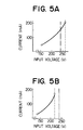
- Figure 5B illustrates the relationship between input voltage and current for the synchronous motor of the conventional type shown in Figures 1 and 2.
- the range shown by a solid line is a range of normal rotation, while irregular rotation occurs when the input voltage exceeds the level shown by a broken line (220 volts, for example).
- the motor can certainly not operate at a working voltage of 240 volts as shown be a chain line in the figure.
- the behaviour of the rotor 4 is as follows.
- an A.C. input voltage applied to the excitation coils 2 is gradually increased from zero.
- the rotor 4 follows a cycle of oscillation - irregular rotation - normal rotation - irregular rotation - oscillation.
- the current flowing in the excitation coils 2 also remains low, and the torque exerted on the rotor 4 is often smaller than the moment of inertia of the rotor 4. In these circumstances, the rotor4 simply cannot rotate, or merely oscillates
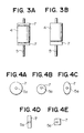
- Figures 3Aand 3B show an inertial-mass element 7 made of a non-magnetic material, such as lead, zinc, copper and stainless steel, formed into a plate shape and fitted integrally to one or both ends of the rotor 4.
- a non-magnetic material such as lead, zinc, copper and stainless steel
- the inertial-mass element 7 was made of a ferromagnetic material, such as steel, and incorporated between the magnetic poles 1a and 1a of the stator 1, as shown in Figures 1 and 2, it would adversely affect the amount and distribution of magnetic fluxes exerted on the rotor 4.
- the element 7 should preferably be made of a non-magnetic material.
- the contour of the inertial-mass element 7 projected on a plan orthogonally intersecting the axis of the rotor 4 can assume various geometrical shapes as shown in Figures 4A through 4E. Each of these Figures shows a hole 5a for the rotating shaft 5 shown in Figures 3A and 3B.
- the range of input voltage where normal rotation is possible for a synchronous motor embodying this invention is approximately 150 - 260 volts, a significantly higher range, compared with Figure 5B illustrating the range for a known synchronous motor. Consequently, a synchronous motor of the invention can satisfactorily continue normal rotation even at an input voltage of 240 volts as shown by a chain line in Figure 5A.
- synchronous motors having a Japanese standard voltage rating of 200 volts can be used in the European Community area (230réss), and even when inputvol- tage fluctuates, they can maintain normal rotation without irregular rotation up to about 260 volts, for example.
- each inertial-mass element 7 is formed into a plate having a hole in which the rotation shaft 5 is received.
- Each element 7 may however, be fitted more directly to an end face of the rotor 4.
- the shape, dimensions, fixing means, etc of the element 7 may be selected appropriately so long as the inertial-mass element 7 does not interfere with the stator 1 and other component members in the end cap 3 (refer to Figures 1 and 2).
- the stator 1 of a substantially U-shape in cross section intersecting orthogonally with the rotating shaft 5 has been described in the above embodiment, stators of other shapes can achieve the same effects.
Landscapes
- Engineering & Computer Science (AREA)
- Power Engineering (AREA)
- Permanent Magnet Type Synchronous Machine (AREA)
- Synchronous Machinery (AREA)
- Connection Of Motors, Electrical Generators, Mechanical Devices, And The Like (AREA)
- Iron Core Of Rotating Electric Machines (AREA)
- Permanent Field Magnets Of Synchronous Machinery (AREA)
Applications Claiming Priority (2)
| Application Number | Priority Date | Filing Date | Title |
|---|---|---|---|
| JP5387692U JPH0617371U (ja) | 1992-07-31 | 1992-07-31 | 同期電動機 |
| JP53876/92 | 1992-07-31 |
Publications (2)
| Publication Number | Publication Date |
|---|---|
| EP0581598A1 true EP0581598A1 (de) | 1994-02-02 |
| EP0581598B1 EP0581598B1 (de) | 1996-09-18 |
Family
ID=12954952
Family Applications (1)
| Application Number | Title | Priority Date | Filing Date |
|---|---|---|---|
| EP19930306015 Expired - Lifetime EP0581598B1 (de) | 1992-07-31 | 1993-07-29 | Synchronmotor |
Country Status (4)
| Country | Link |
|---|---|
| EP (1) | EP0581598B1 (de) |
| JP (1) | JPH0617371U (de) |
| CN (1) | CN1036038C (de) |
| DE (1) | DE69304836T2 (de) |
Cited By (1)
| Publication number | Priority date | Publication date | Assignee | Title |
|---|---|---|---|---|
| EP2025944A1 (de) * | 2007-08-09 | 2009-02-18 | Askoll Holding S.r.l. | Einphasiger Synchronmotor für Hausgeräten |
Families Citing this family (3)
| Publication number | Priority date | Publication date | Assignee | Title |
|---|---|---|---|---|
| JP3877620B2 (ja) * | 2002-03-18 | 2007-02-07 | 三洋電機株式会社 | 集中巻式dcモータ及びそれを搭載したコンプレッサ |
| CN101697443A (zh) * | 2009-10-30 | 2010-04-21 | 无锡新大力电机有限公司 | 永磁三相同步电机转子端部结构 |
| CN113783352A (zh) * | 2021-08-26 | 2021-12-10 | 浙江光悦电机有限公司 | 一种节能交流电机 |
Citations (1)
| Publication number | Priority date | Publication date | Assignee | Title |
|---|---|---|---|---|
| DE8807108U1 (de) * | 1988-05-31 | 1989-03-30 | Siemens AG, 1000 Berlin und 8000 München | Einphasen-Synchronmotor |
Family Cites Families (5)
| Publication number | Priority date | Publication date | Assignee | Title |
|---|---|---|---|---|
| JPS5992755A (ja) * | 1982-11-17 | 1984-05-29 | Matsushita Electric Ind Co Ltd | 永久磁石回転子型の同期電動機 |
| US4629999A (en) * | 1983-12-27 | 1986-12-16 | North American Philips Corp. | Phase-locked loop capable of generating a plurality of stable frequency signals |
| FI71446C (fi) * | 1985-06-06 | 1986-12-19 | Kone Oy | Elmotor |
| JPS6292748A (ja) * | 1985-10-18 | 1987-04-28 | Sanyo Electric Co Ltd | 同期電動機 |
| JP2826156B2 (ja) * | 1990-03-15 | 1998-11-18 | イビデン株式会社 | スピンドルモータ |
-
1992
- 1992-07-31 JP JP5387692U patent/JPH0617371U/ja active Pending
-
1993
- 1993-07-29 EP EP19930306015 patent/EP0581598B1/de not_active Expired - Lifetime
- 1993-07-29 DE DE1993604836 patent/DE69304836T2/de not_active Expired - Fee Related
- 1993-07-31 CN CN93109399A patent/CN1036038C/zh not_active Expired - Fee Related
Patent Citations (1)
| Publication number | Priority date | Publication date | Assignee | Title |
|---|---|---|---|---|
| DE8807108U1 (de) * | 1988-05-31 | 1989-03-30 | Siemens AG, 1000 Berlin und 8000 München | Einphasen-Synchronmotor |
Non-Patent Citations (5)
| Title |
|---|
| FEINWERKTECHNIK & MESSTECHNIK vol. 87, no. 4, June 1979, MüNCHEN DE pages 163 - 169 H.SCHEMMANN 'Zweipolige Einphasen-Synchronmotoren mit dauer-magnetischem L{ufer' * |
| FEINWERKTECHNIK & MESSTECHNIK vol. 93, no. 3, April 1985, MüNCHEN DE pages 145 - 147 DIPL.-ING. H.J.PLAUMANN 'Zweipoliger Einphasen-Synchronmotor mit hochremanentem Permanentmagnet-Rotor' * |
| PATENT ABSTRACTS OF JAPAN vol. 016, no. 200 (E-1201)13 May 1992 & JP-A-04 029554 ( FUJI ELECTRIC CO. LTD. ) 31 January 1992 * |
| PATENT ABSTRACTS OF JAPAN vol. 10, no. 65 (E-388)(2122) 14 March 1986 & JP-A-60 216751 ( ASUMO K.K. ) 30 October 1985 * |
| PATENT ABSTRACTS OF JAPAN vol. 11, no. 294 (E-544)22 September 1987 & JP-A-62 092748 ( SANYO ELECTRIC CO. LTD. ) 28 April 1987 * |
Cited By (2)
| Publication number | Priority date | Publication date | Assignee | Title |
|---|---|---|---|---|
| EP2025944A1 (de) * | 2007-08-09 | 2009-02-18 | Askoll Holding S.r.l. | Einphasiger Synchronmotor für Hausgeräten |
| EP2025944B1 (de) | 2007-08-09 | 2017-08-09 | Askoll Holding S.r.l. | Einphasiger Synchronmotor für Hausgeräte |
Also Published As
| Publication number | Publication date |
|---|---|
| DE69304836T2 (de) | 1997-01-30 |
| JPH0617371U (ja) | 1994-03-04 |
| DE69304836D1 (de) | 1996-10-24 |
| CN1036038C (zh) | 1997-10-01 |
| CN1081792A (zh) | 1994-02-09 |
| EP0581598B1 (de) | 1996-09-18 |
Similar Documents
| Publication | Publication Date | Title |
|---|---|---|
| EP1414130B1 (de) | Elektromotor mit Dauermagnetläufer | |
| US5041749A (en) | High speed, high power, single phase brushless DC motor | |
| US4575652A (en) | Permanent magnet motor having high starting torque and narrowly-defined detent zones | |
| US5523637A (en) | Permanent magnet electrical machine with low reluctance torque | |
| EP0601818A1 (de) | Geschaltete Reluktanzmotoren | |
| EP1261103B1 (de) | Bürstenloser Gleichstrommotor | |
| US4651040A (en) | Induction motor | |
| US6803690B2 (en) | Electric motor excited by permanent magnets | |
| KR100885737B1 (ko) | 스텝핑 모터 | |
| EP1303030A2 (de) | Permanentmagnet-Schrittmotor | |
| EP1271751B1 (de) | Elektrische Maschine mit rhombusförmigen Permanentmagneten | |
| EP0581598B1 (de) | Synchronmotor | |
| KR20090079681A (ko) | 브러쉬리스 직류 모터 | |
| US20060220475A1 (en) | Stepping motor and fan having the same | |
| US3421032A (en) | Synchronous reaction motor with deadshaft rotor mount | |
| WO2021229954A1 (ja) | 回転子及び電動機 | |
| US7586229B2 (en) | Continuous rotary motor | |
| JP2005057940A (ja) | 回転電機 | |
| JPS6337590B2 (de) | ||
| EP3484025B1 (de) | Aktuator mit einstellbarer passiver eigenschaft und aktiver anpassung dieser eigenschaft | |
| KR0158748B1 (ko) | 초기 회전력을 갖는 스위치드 릴럭턴스 모터 | |
| JPS6292748A (ja) | 同期電動機 | |
| KR20030048582A (ko) | 편평형 진동 모터 | |
| JPH0456543B2 (de) | ||
| KR200154479Y1 (ko) | 전자석식 교류 저속 동기모터 |
Legal Events
| Date | Code | Title | Description |
|---|---|---|---|
| PUAI | Public reference made under article 153(3) epc to a published international application that has entered the european phase |
Free format text: ORIGINAL CODE: 0009012 |
|
| AK | Designated contracting states |
Kind code of ref document: A1 Designated state(s): DE FR GB IT |
|
| 17P | Request for examination filed |
Effective date: 19940801 |
|
| 17Q | First examination report despatched |
Effective date: 19950301 |
|
| GRAH | Despatch of communication of intention to grant a patent |
Free format text: ORIGINAL CODE: EPIDOS IGRA |
|
| GRAH | Despatch of communication of intention to grant a patent |
Free format text: ORIGINAL CODE: EPIDOS IGRA |
|
| GRAA | (expected) grant |
Free format text: ORIGINAL CODE: 0009210 |
|
| AK | Designated contracting states |
Kind code of ref document: B1 Designated state(s): DE FR GB IT |
|
| REF | Corresponds to: |
Ref document number: 69304836 Country of ref document: DE Date of ref document: 19961024 |
|
| ET | Fr: translation filed | ||
| ITF | It: translation for a ep patent filed | ||
| PLBE | No opposition filed within time limit |
Free format text: ORIGINAL CODE: 0009261 |
|
| STAA | Information on the status of an ep patent application or granted ep patent |
Free format text: STATUS: NO OPPOSITION FILED WITHIN TIME LIMIT |
|
| 26N | No opposition filed | ||
| REG | Reference to a national code |
Ref country code: GB Ref legal event code: IF02 |
|
| PGFP | Annual fee paid to national office [announced via postgrant information from national office to epo] |
Ref country code: FR Payment date: 20040708 Year of fee payment: 12 |
|
| PGFP | Annual fee paid to national office [announced via postgrant information from national office to epo] |
Ref country code: GB Payment date: 20040728 Year of fee payment: 12 |
|
| PGFP | Annual fee paid to national office [announced via postgrant information from national office to epo] |
Ref country code: DE Payment date: 20040806 Year of fee payment: 12 |
|
| PG25 | Lapsed in a contracting state [announced via postgrant information from national office to epo] |
Ref country code: IT Free format text: LAPSE BECAUSE OF NON-PAYMENT OF DUE FEES;WARNING: LAPSES OF ITALIAN PATENTS WITH EFFECTIVE DATE BEFORE 2007 MAY HAVE OCCURRED AT ANY TIME BEFORE 2007. THE CORRECT EFFECTIVE DATE MAY BE DIFFERENT FROM THE ONE RECORDED. Effective date: 20050729 Ref country code: GB Free format text: LAPSE BECAUSE OF NON-PAYMENT OF DUE FEES Effective date: 20050729 |
|
| PG25 | Lapsed in a contracting state [announced via postgrant information from national office to epo] |
Ref country code: DE Free format text: LAPSE BECAUSE OF NON-PAYMENT OF DUE FEES Effective date: 20060201 |
|
| GBPC | Gb: european patent ceased through non-payment of renewal fee |
Effective date: 20050729 |
|
| PG25 | Lapsed in a contracting state [announced via postgrant information from national office to epo] |
Ref country code: FR Free format text: LAPSE BECAUSE OF NON-PAYMENT OF DUE FEES Effective date: 20060331 |
|
| REG | Reference to a national code |
Ref country code: FR Ref legal event code: ST Effective date: 20060331 |