EP0581804B2 - Fermeture protegee contre la surpression - Google Patents
Fermeture protegee contre la surpression Download PDFInfo
- Publication number
- EP0581804B2 EP0581804B2 EP92908785A EP92908785A EP0581804B2 EP 0581804 B2 EP0581804 B2 EP 0581804B2 EP 92908785 A EP92908785 A EP 92908785A EP 92908785 A EP92908785 A EP 92908785A EP 0581804 B2 EP0581804 B2 EP 0581804B2
- Authority
- EP
- European Patent Office
- Prior art keywords
- closure
- casing
- accordance
- region
- extension section
- Prior art date
- Legal status (The legal status is an assumption and is not a legal conclusion. Google has not performed a legal analysis and makes no representation as to the accuracy of the status listed.)
- Expired - Lifetime
Links
Images


Classifications
-
- B—PERFORMING OPERATIONS; TRANSPORTING
- B65—CONVEYING; PACKING; STORING; HANDLING THIN OR FILAMENTARY MATERIAL
- B65D—CONTAINERS FOR STORAGE OR TRANSPORT OF ARTICLES OR MATERIALS, e.g. BAGS, BARRELS, BOTTLES, BOXES, CANS, CARTONS, CRATES, DRUMS, JARS, TANKS, HOPPERS, FORWARDING CONTAINERS; ACCESSORIES, CLOSURES, OR FITTINGS THEREFOR; PACKAGING ELEMENTS; PACKAGES
- B65D51/00—Closures not otherwise provided for
- B65D51/16—Closures not otherwise provided for with means for venting air or gas
- B65D51/1633—Closures not otherwise provided for with means for venting air or gas whereby venting occurs by automatic opening of the closure, container or other element
- B65D51/1638—Closures not otherwise provided for with means for venting air or gas whereby venting occurs by automatic opening of the closure, container or other element by means of an element bursting upon a predetermined pressure in the container being exceeded
-
- B—PERFORMING OPERATIONS; TRANSPORTING
- B65—CONVEYING; PACKING; STORING; HANDLING THIN OR FILAMENTARY MATERIAL
- B65D—CONTAINERS FOR STORAGE OR TRANSPORT OF ARTICLES OR MATERIALS, e.g. BAGS, BARRELS, BOTTLES, BOXES, CANS, CARTONS, CRATES, DRUMS, JARS, TANKS, HOPPERS, FORWARDING CONTAINERS; ACCESSORIES, CLOSURES, OR FITTINGS THEREFOR; PACKAGING ELEMENTS; PACKAGES
- B65D79/00—Kinds or details of packages, not otherwise provided for
- B65D79/005—Packages having deformable parts for indicating or neutralizing internal pressure-variations by other means than venting
- B65D79/0087—Packages having deformable parts for indicating or neutralizing internal pressure-variations by other means than venting the deformable part being located in a closure, e.g. in caps or lids
Definitions
- the invention relates to a closure for containers with a closure mirror that closes the mouth region of the container and with a jacket that extends from the latter and that has a locking device — generally a screw thread — that interacts with the outside of the container.
- the preamble of claim 1 is based on this closest prior art and is disclosed therein. It is therefore an object of the invention to provide a closure for containers, which releases the mouth region of the container at an overpressure and enables the excess pressure to be reduced.
- the pressure relief valve is designed such that the closure mirror lifts off the mouth area of the container as a whole at a predetermined internal pressure, blowing off can be ensured with a particularly high degree of safety because overpressure can also be reduced when individual areas of the opening slot of the pressure relief valve are displaced by the contents of the container. This can be the case in particular with mushy contents of the container.
- An embodiment of the closure is preferred, in which the expansion path of the pressure relief valve is arranged at a distance from the transition between the jacket and the closure mirror.
- the resulting edge which surrounds the locking mirror, stabilizes it so that it can withstand high internal pressures. The blow-off properties are not affected.
- the transition region between the closure mirror and the jacket is subjected to a deep-drawing process.
- the greater the depth of draw the higher the blow-off pressure, i.e. the pressure at which the pressure relief valve trips.
- the edge region solidifies over the expansion path, so that the pressure prevailing in the container until the blow-off pressure is reached is held more securely.
- an embodiment of the closure is preferred, which is characterized in that at least individual reinforcement zones are provided between the transition from the closure mirror and the jacket and the stretch. These lead to a further stiffening of the closure and increase its functional reliability.
- an embodiment of the closure is preferred in which at least individual stiffening zones are provided in the casing between the stretching section and the locking device. This design ensures that the axial forces occurring in the case of an overpressure in the jacket are concentrated on the expansion path, so that deformations in the remaining jacket area are reduced, if not completely excluded.
- closures are preferred in which the locking device is provided with stiffeners.
- Such closures are suitable for closing containers with a particularly high internal pressure because deformations of the locking area up to high internal pressures are avoided.
- the expansion path is designed as a continuous ring area in the jacket of the closure. This construction ensures a uniform lifting of the closure mirror from the mouth area, so that the blow-off pressure can be predetermined very precisely.
- the closure in which the stretch is formed by a wall region of the jacket which extends under an arc and is curved outwards.
- a sheet is easy to manufacture, and therefore inexpensive to manufacture. It can be expanded in the case of an overpressure in the container, so that the closure level rises from the mouth region of the container.
- the expansion path has two interconnected wall sections which run at an angle to one another.
- the expansion path is thus quasi V-shaped and can also be widened when the container is under internal pressure. It is also easy and inexpensive to manufacture such an expansion section.
- a closure is particularly preferred in which the expansion properties of the expansion section are adjustable.
- Such a closure can be used universally and can be adapted to different internal pressures.
- the flexibility of the stretch can be reduced by a special shape or increased by slots, depending on which internal pressures are to be securely closed with this closure.
- the closure described below is suitable for closing a wide variety of containers that are under positive pressure.
- the closure is preferably used, for example, for bottles, the contents of which are under pressure, which, if increased too much, could lead to a blow-off of the closure, but could also cause the bottle to burst and thus endanger the consumer.
- closures can be equipped with a locking device designed as a continuous screw thread, as a thread attachment, as a bayonet closure or as a snap closure with a pressure relief valve which is explained in more detail below.
- closures are basically freely selectable. In the following, however, closures are explained in the figures, which consist of a thermoformable material, preferably aluminum.
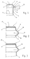
- FIG. 1 shows a first exemplary embodiment of a closure 1 for containers made of aluminum, which has a closure mirror 3, which closes the mouth region of the container to be closed, and a jacket 5 extending from it.
- a seal 7 is provided on the underside of the closure mirror. Both disc and compound seals as well as stamped seals can be used for the function of the closure.
- Figure 1 shows a profiled cap blank, the wall of which has no locking device, in particular no threads. These are only introduced into the wall after the closure has been placed on a bottle, preferably by a rolling or embossing process.
- a guarantee ring 9 is provided in the lower casing area in that a horizontal cut 11 has been made at a distance from the lower edge of the casing, the individual small tear-off webs 13 remains intact. Below the horizontal cutting line, vertical weakening lines, so-called vertical incisions, not shown here, can also be provided, so that individual ring segments are formed when the guarantee ring is opened during the first opening of the closure.
- a distance 15 is provided at a distance from the transition area between the closing mirror 3 and the jacket 5.
- the stretch is formed by an outwardly projecting or curved area of the jacket 5.
- Individual areas of this type, or, as in the exemplary embodiment shown here in accordance with FIG. 1, a continuous ring area can be provided for the expansion section 15.
- the expansion path consists of two wall sections 17 and 19 which run at an angle ⁇ to one another and which merge into a connecting region 21 which runs at a radius.
- the connection area is arched here under a radius R.
- the angle ⁇ can be varied in a further range, depending on which expansion properties the expansion path should have.
- the angle ⁇ can be in a range from 180 ° to 3 °, preferably from 100 ° to 20 °, in particular in a range from approximately 45 ° to 30 °.
- the bisector 23 of the angle ⁇ is approximately perpendicular to the central axis 25 of the closure.
- the expansion path is also possible for the expansion path to be asymmetrical and for the bisector to run at an angle of, for example, 10 ° to the horizontal.
- one of the wall sections can run essentially horizontally and the other at an angle to it.
- the two wall sections can also be arranged practically horizontally and connected to one another in their end region.
- FIG. 2 which in turn represents a partial section through a closure 1, shows an asymmetrical expansion path 15, the upper wall area 17 of which is approximately rectilinear, while the lower wall area 19 follows a curve and merges practically seamlessly into the connecting area 21, which is under one Radius R runs. The stretch is arched outwards relative to the rest of the casing of the closure 1.
- FIG. 3 again shows an enlarged partial section through an expansion section 15 of a closure 1.
- the same parts are again provided with the same reference numerals, so that their description is omitted here.
- the expansion path is arc-shaped, in particular circular-arc-shaped, the radius of curvature being practically the same everywhere.
- the stretch is here symmetrical, that is, the axis of symmetry 23 'of the stretch 15 is approximately perpendicular to the central axis 25 of the closure 1.
- FIG. 4 shows a side view of the upper edge of a further exemplary embodiment of a closure 1, which is provided with a knurling or with reinforcing beads 27 above the expansion path 15.
- the closing mirror 3 is surrounded by a particularly stable wall area.
- An axial expansion of the jacket 5 in the event of an overpressure in the container therefore does not have as great an effect on the wall area below the closing mirror.
- the expansion forces that lead to axial forces in the jacket 5 are therefore introduced particularly well into the expansion section 15.
- the expansion section 15 is provided with knurling or with reinforcing beads 29.
- the longitudinal axis of the beads which is essentially vertical here, can also be arranged obliquely.
- the beads lead to a stiffening of the expansion section 15 itself, so that a closure of this type will only react to higher overpressures in the interior of the closed container than those explained with reference to FIGS. 1 to 4.
- knurling can also be provided additionally or exclusively on the wall areas 17 and / or 19.
- the side view of the corner region of a closure 1 in FIG. 6 clearly shows that it is also possible to weaken the stretch 15. This is achieved in the embodiment shown here in that 15 slots 31 are made in the walls of the expansion section, which lead to the fact that the expansion section is deformed at a lower internal pressure in the container, so that the closure mirror 3 from the mouth area of the to be closed Can lift container and the excess pressure is reduced.
- Sieves 33 remain between the incisions or slots 31 in the expansion section 15, the width of which is the strength of the Determine the stretch and its expansion behavior in the event of overpressure.
- the width By choosing the width, the pressure can be determined at which the sealing mirror 3 lifts off the mouth of a container and allows the excess pressure to be blown off.
- FIG. 7 finally shows a further embodiment of a closure 1 which is not claimed and which is reproduced for the purpose of refining the rint tips and which has a jacket 5 starting from a closure mirror 3.
- the jacket is provided below the closure mirror with an expansion path 15, which is formed by the fact that several adjacent slots 31 have been made directly in the jacket 5.
- the width of the webs 33 which remain stationary can be selected so that, at certain, predetermined internal pressures in the container, expansion occurs within these webs, so that the closure mirror 30 releases the mouth region of the container to be closed and the excess pressure is reduced.
- expansion section 15 is particularly suitable for plastic closures.
- the slots 31 are arranged vertically, for example, that is, they run in the direction of the central axis 25 of the closure. However, it is also possible for the slots to form an angle with the vertical, that is to say they are introduced obliquely into the casing 5.
- FIG. 7 shows rectangular slots 31 as an example.
- the slots any shape, for example an S-shape, or to arrange them along a helical line parallel to one another in a region which corresponds approximately to the height of the slots 31 in FIG. 7.
- FIG. 7 as an example for all closures that have been described with reference to FIGS. 1 to 7, an edge that can be produced by a deep-drawing process is shown in broken lines in the transition region between the closure mirror 3 and the jacket 5.
- the seal 7 visible in FIGS. 1 to 3 is molded onto the mouth region of the container to be closed and also pressed against the side wall of the container. This creates a pressure-tight closure of the container.
- the height of the deep-drawing edge or by the depth of the drawing which can be varied in a range between 0.3 mm and for example 4.5 mm and preferably 1 mm blow-off pressure can be set very precisely.
- the lower the height of the deep-drawing edge 35 the lower the pressure at which the closing mirror 3 lifts off the mouth area of the container due to the flexibility of the stretching path 15.
- the stretch properties of the stretch section 15 can be set in various ways.
- the wall material can be varied and / or the wall thickness of the jacket can be reduced or strengthened in the region of the stretch, depending on which internal pressures are to be closed.
- the shape of the expansion section also plays a major role in its expansion behavior.
- the expansion forces differ depending on the included angle ⁇ of the wall sections 17 and 19.
- the radius R in the connection area 21 also has an effect here. The larger the angle ⁇ is and the larger the radius is selected, the "softer" the stretch is, ie it yields at lower internal pressures.
- a softening of the stretching range is also possible in that, for example, slots 31 running perpendicular to the longitudinal axis of the closure are made in particular in the walls of the stretching section 15 (see FIG. 6).
- the stretch behavior will determined by the webs 33 located between the incisions 31. The wider these webs are, the harder is the stretch mark 15.
- the slots 31 can also be arranged obliquely with respect to the vertical.
- This principle of the slits can also be applied to a closure shown in FIG. 7, the expansion area of which is formed exclusively from such slits and which otherwise remains undeformed in this area, that is to say has no bulge, as shown in FIGS. 1 to 6.
- the webs remaining between the slots determine the axial extent of the closure 1 in the event of an overpressure in the interior of the container. The thinner the webs, the sooner the closure mirror 3 will lift off the mouth area of the container and let the internal pressure be blown off.
- the closure described last which is also shown in FIG. 7, is characterized in that a deformation of the expansion section 15 is irreversible, in particular in the case of closures made of aluminum. This means that if the expansion path 15 has been widened by an overpressure, so that the closure mirror 3 lifts off from the mouth region of the container, the container will not be closed again. If necessary, however, a resilient plastic can be achieved even with such a configuration of the closure, so that the container is closed again even after an excess pressure has been blown off.
- the expansion path 15 is arranged at a distance from the transition region of the jacket 5 to the mirror 3, this is surrounded by a stable edge, which does not deform even under excess pressure. This gives this part of the valve great stability, which ensures a very precise repeatability of the blow-off process.
- the area between the expansion section 15 and the closure mirror 3 can be stabilized by reinforcing beads 27. This results in a particularly high strength in the head region of the closure or in the closure mirror integrated therein 3, expansion section 15 and jacket 5 formed pressure relief valve, so that even high internal pressures can be held securely and released exactly when a certain limit value is exceeded.
- a further stabilization of the closure is also possible by means of reinforcing beads below the expansion section 15, which may also extend into a threaded area.
- the reinforcements in the thread ensure that the closure cannot be blown off when the internal pressure is high, which would endanger consumers.
- the reinforcements in the jacket area between the thread serving as a locking device and the expansion section serve to prevent the closure from being deformed in the event of overpressure in the container.
- axial forces occurring in the jacket 5 are introduced particularly well into the expansion area of the expansion section, so that the expansion behavior is very predictable.
- the pressure at which the pressure relief valve will open can be precisely predetermined.
- the closure 1 provided with the integrated pressure relief valve is thus universally usable. Even when using guarantee rings, which are combined with aluminum caps, for example, the desired expansion behavior of the expansion section is retained.
- guarantee rings which are combined with aluminum caps, for example, the desired expansion behavior of the expansion section is retained.
- the expansion area 15 can subsequently take over the desired expansion function in the jacket area of the closure, because the strength of the expansion section 15 can also be matched to the forces which occur when a container is first closed. It is therefore readily possible to use a closure 1 with a pressure relief valve also in connection with guarantee rings, irrespective of whether these are integrated directly into the casing area of the closure, as explained with reference to FIG. 1, or whether these are separate parts are executed.
- the stretching section 15 can be introduced very easily into a metal closure by an embossing, deep-drawing or rolling process, without the production costs for such a closure would be significantly affected.
- stretching sections of the type described here see in particular FIG. 7 can easily be provided without the production costs being adversely affected.
- the outer shape of the closure is not affected by the integrated pressure relief valve, which is formed by the expansion path and the closure level.
- advertising prints can continue to be applied to the outside of the closure.
- the overpressure at which the closure blows off is also determined by the fact that the height of the expansion section 15 can be varied, that is to say the area of the jacket 5 affected overall by the deformation. This also applies to the closure according to FIG the length of the slots 31 is adjustable.
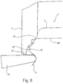
- a special deep-drawing tool referred to as a plunger 41
- a plunger 41 is used for the transition region between the closure mirror 3 and the casing 5 of the closure 1.
- This is a cylindrical sleeve which is moved over the closure 1 already placed on a container to be closed and then lowered.
- a deep-drawn edge 43 engages at the transition area between the closure mirror 3 and the casing 5 and deforms this area, so that the seal present in the interior of the closure is pressed onto the upper mouth region, of the container to be closed and on its side wall.
- this transition region is solidified.
- the depth of the drawing that is to say the height of the deep-drawing edge 35 which arises during the deep-drawing process, can be varied. It has already been stated above that the greater the depth of draw, the higher the pressure held by the closure.
- the inner wall of the plunger has a precentering area 45 which has a larger inner diameter than the deep-drawing edge and which is provided with a conical wall area which tapers from bottom to top.
- the pre-centering area 45 has an inner diameter such that the expansion path 15 is arranged in the interior of the plunger 41 without contact when the deep-drawing process has ended and the plunger 41 is in its lowest position.
Landscapes
- Engineering & Computer Science (AREA)
- Mechanical Engineering (AREA)
- Closures For Containers (AREA)
- Medical Preparation Storing Or Oral Administration Devices (AREA)
Claims (23)
- Fermeture (1) en matière plastique ou en métal emboutissable pour récipients restant sous pression, comportant un panneau obturateur (3) fermant la zone de la bouche du récipient et pourvu, sur sa face inférieure tournée vers la zone de bouche, d'un joint d'étanchéité (7) au moins dans la zone où il s'appuie sur la bouche du récipient, et comportant une chemise (5) partant de ce panneau, qui présente un dispositif de verrouillage coopérant avec la face extérieure du récipient, caractérisée par une soupape de surpression comprenant le panneau obturateur (3), la chemise (5) et une zone de dilatation périphérique (15) prévue dans la chemise (5), limitée en direction axiale, formée par une zone de la chemise (5) faisant saillie ou courbée vers l'extérieur, laquelle soupape est actionnée pour une pression intérieure fixée dans le récipient par la zone de dilatation (15) permettant une dilatation axiale de la chemise (5), et est conçue de façon que, pour une pression intérieure donnée, le panneau obturateur (3) se soulève en bloc de la zone de la bouche du récipient.
- Fermeture selon la revendication 1, caractérisée par le fait que la zone de dilatation (15) est placée à une certaine distance de la jonction entre la chemise (5) et le panneau obturateur (3).
- Fermeture selon l'une des revendications 1 et 2, caractérisée par le fait que la zone de jonction entre le panneau obturateur (3) et la chemise (5) a été soumise à un emboutissage pour la fixation de la pression de décharge à la valeur désirée.
- Fermeture selon l'une des revendications 1 à 3, caractérisée par le fait qu'entre la jonction du panneau obturateur (3) et de la chemise (5) et la zone de dilatation (15) sont prévues des zones de renfort au moins séparées.
- Fermeture selon l'une des revendications 1 à 4, caractérisée par le fait que des zones de renfort au moins séparées sont prévues dans la chemise (5) entre la zone de dilatation (15) et le dispositif de verrouillage.
- Fermeture selon l'une des revendications précédentes, caractérisée par le fait que le dispositif de verrouillage est pourvu de renforts.
- Fermeture selon l'une des revendications précédentes, caractérisée par le fait que la zone de dilatation (15) est formée d'une zone annulaire continue faite dans la chemise (5).
- Fermeture selon l'une des revendications précédentes, caractérisée par le fait que la zone de dilatation (15) est formée par une partie de paroi de la chemise (5) s'étendant sur un arc, de préférence un arc de cercle, cette partie de paroi arquée étant courbée vers l'extérieur.
- Fermeture selon l'une des revendications 1 à 7, caractérisée par le fait que la zone de dilatation (15) présente deux tronçons de paroi joints (17, 19) qui font entre eux un angle (α) dont le sommet se trouve à peu près dans la zone de jonction (21) des deux tronçons de paroi et qui s'ouvre vers l'intérieur de la fermeture (1) entouré par la chemise (5).
- Fermeture selon la revendication 9, caractérisée par le fait que l'angle (α) est compris entre 180° et 3°, de préférence 100° et 20°, en particulier entre 45° et 30°.
- Fermeture selon l'une des revendications 9 et 10, caractérisée par le fait que la bissectrice (23) de l'angle (α) est perpendiculaire à l'axe (25) de la fermeture (1).
- Fermeture selon l'une des revendications 9 à 11, caractérisée par le fait que les deux tronçons de paroi (17, 19) se fondent l'un dans l'autre dans une zone de jonction (21) avec un rayon (R).
- Fermeture selon l'une des revendications précédentes, caractérisée par le fait que les caractéristiques de dilatation de la zone de dilatation (15) sont réglables.
- Fermeture selon l'une des revendications 9 à 13, dans la mesure où cette dernière est rattachée à l'une des revendications 9 à 12, caractérisée par le fait que les caractéristiques de dilatation de la zone de dilatation (15) peuvent être réglées par le choix spécial de l'épaisseur de paroi dans la zone de jonction (21) entre les tronçons de paroi et/ou dans la zone de la jonction entre la chemise (5) et la zone de dilatation (15).
- Fermeture selon l'une quelconque des revendications 9 à 14, caractérisée par le fait que pour augmenter la force de dilatation, des déformations de la zone de dilatation (15, en particulier des moulures, sont prévues dans la zone de jonction (21).
- Fermeture selon l'une des revendications 9 à 14, caractérisée par le fait que pour diminuer les forces de dilatation, des entailles (31) sont prévues dans la zone de dilatation (15).
- Fermeture selon l'une des revendications 1 à 7, caractérisée par le fait que la zone de dilatation (15) peut être réalisée par une réduction de l'épaisseur de paroi et/ou par des entailles faites dans la chemise (5).
- Fermeture selon l'une des revendications précédentes, caractérisée par le fait que le panneau obturateur (3) et la chemise (5) sont en aluminium.
- Fermeture selon l'une des revendications précédentes, caractérisée par le fait que pour la formation d'une bague de garantie (9), la chemise (5) est pourvue dans sa zone d'extrémité opposée au panneau obturateur (3) d'entailles horizontales et verticales.
- Fermeture selon l'une des revendications 1 à 18, caractérisée par une bague de garantie séparée de préférence en plastique qui est tenue par le bord inférieur de la chemise.
- Fermeture selon l'une des revendications 1 à 17, caractérisée par le fait que le panneau obturateur (3) et la chemise (5) sont en matière plastique.
- Fermeture selon la revendication 21, caractérisée par une bague de garantie tenue par la chemise (5) ou faite dans le bord inférieur de celle-ci.
- Fermeture selon l'une des revendications précédentes, caractérisée par le fait que le dispositif de verrouillage est constitué d'un filetage continu, d'un nez fileté, de tronçons de filetage, d'une fermeture à ressort ou d'une fermeture à baïonnette.
Applications Claiming Priority (3)
| Application Number | Priority Date | Filing Date | Title |
|---|---|---|---|
| DE4113428 | 1991-04-25 | ||
| DE4113428A DE4113428C3 (de) | 1991-04-25 | 1991-04-25 | Schraubverschluß |
| PCT/EP1992/000866 WO1992019510A1 (fr) | 1991-04-25 | 1992-04-18 | Fermeture protegee contre la surpression |
Publications (3)
| Publication Number | Publication Date |
|---|---|
| EP0581804A1 EP0581804A1 (fr) | 1994-02-09 |
| EP0581804B1 EP0581804B1 (fr) | 1994-09-21 |
| EP0581804B2 true EP0581804B2 (fr) | 1997-01-22 |
Family
ID=6430290
Family Applications (1)
| Application Number | Title | Priority Date | Filing Date |
|---|---|---|---|
| EP92908785A Expired - Lifetime EP0581804B2 (fr) | 1991-04-25 | 1992-04-18 | Fermeture protegee contre la surpression |
Country Status (5)
| Country | Link |
|---|---|
| EP (1) | EP0581804B2 (fr) |
| AT (1) | ATE111854T1 (fr) |
| AU (1) | AU1579392A (fr) |
| DE (2) | DE4113428C3 (fr) |
| WO (1) | WO1992019510A1 (fr) |
Families Citing this family (7)
| Publication number | Priority date | Publication date | Assignee | Title |
|---|---|---|---|---|
| US5533752A (en) * | 1994-11-08 | 1996-07-09 | Trw Vehicle Safety Systems Inc. | Apparatus for restraining movement of an occupant of a vehicle |
| US7726165B2 (en) | 2006-05-16 | 2010-06-01 | Alcoa Inc. | Manufacturing process to produce a necked container |
| US7934410B2 (en) | 2006-06-26 | 2011-05-03 | Alcoa Inc. | Expanding die and method of shaping containers |
| EA025944B1 (ru) | 2010-08-20 | 2017-02-28 | Алкоа Инк. | Фигурная металлическая емкость и способ ее изготовления |
| US9327338B2 (en) | 2012-12-20 | 2016-05-03 | Alcoa Inc. | Knockout for use while necking a metal container, die system for necking a metal container and method of necking a metal container |
| DE102019128341A1 (de) * | 2019-10-21 | 2021-04-22 | Volkswagen Aktiengesellschaft | Deckelanordnung für einen Behälter |
| US20230159236A1 (en) * | 2021-11-24 | 2023-05-25 | Owens-Brockway Glass Container Inc. | Food or beverage package and container closure |
Family Cites Families (7)
| Publication number | Priority date | Publication date | Assignee | Title |
|---|---|---|---|---|
| US1694851A (en) * | 1927-09-14 | 1928-12-11 | Glass William | Bottle cap |
| US2161097A (en) * | 1935-12-14 | 1939-06-06 | Schroder-Nielsen Thorolf | Closure for bottles and the like |
| GB1207487A (en) * | 1966-11-30 | 1970-10-07 | Metal Closures Ltd | Improved bottle closure |
| US3713545A (en) * | 1971-09-14 | 1973-01-30 | Aluminum Co Of America | Venting closure |
| CA1195290A (fr) * | 1981-06-08 | 1985-10-15 | Efrem M. Ostrowsky | Fermeture pour recipients sous pression |
| DE8321798U1 (de) * | 1983-07-29 | 1983-12-01 | Mauser-Werke GmbH, 5040 Brühl | Verschluss mit Entgasungsventil |
| JPH02503414A (ja) * | 1987-03-27 | 1990-10-18 | トウザーニ、ウイリアム | 新鮮度および異常開封を検知し得る閉鎖具 |
-
1991
- 1991-04-25 DE DE4113428A patent/DE4113428C3/de not_active Expired - Fee Related
-
1992
- 1992-04-18 EP EP92908785A patent/EP0581804B2/fr not_active Expired - Lifetime
- 1992-04-18 AU AU15793/92A patent/AU1579392A/en not_active Abandoned
- 1992-04-18 WO PCT/EP1992/000866 patent/WO1992019510A1/fr not_active Ceased
- 1992-04-18 AT AT92908785T patent/ATE111854T1/de not_active IP Right Cessation
- 1992-04-18 DE DE59200545T patent/DE59200545D1/de not_active Expired - Fee Related
Also Published As
| Publication number | Publication date |
|---|---|
| EP0581804B1 (fr) | 1994-09-21 |
| DE4113428A1 (de) | 1992-10-29 |
| DE4113428C3 (de) | 1999-08-05 |
| DE59200545D1 (de) | 1994-10-27 |
| ATE111854T1 (de) | 1994-10-15 |
| EP0581804A1 (fr) | 1994-02-09 |
| WO1992019510A1 (fr) | 1992-11-12 |
| AU1579392A (en) | 1992-12-21 |
| DE4113428C2 (de) | 1994-01-05 |
Similar Documents
| Publication | Publication Date | Title |
|---|---|---|
| EP0064047B1 (fr) | Fermeture pour bouteille à boisson et bouteille à boisson munis d'une telle fermeture | |
| EP0960054B2 (fr) | Bouteille pet avec fermeture a vis en matiere plastique | |
| EP0661218B1 (fr) | Capuchon de fermeture en matière plastique à joint interne à ventilation précoce | |
| EP1105318B1 (fr) | Capuchon de fermeture | |
| DE60005333T2 (de) | Belüfteter verbundverschluss | |
| DE3650370T2 (de) | Garantieverschluss und verfahren zu seiner herstellung. | |
| EP1429973B1 (fr) | Bouchon a vis | |
| DE4301306C2 (de) | Kunststoffverschluß | |
| EP2566768B1 (fr) | Emballage avec fermeture filetée | |
| WO2000015504A2 (fr) | Bouchon de fermeture | |
| EP0581804B2 (fr) | Fermeture protegee contre la surpression | |
| DE2366001A1 (de) | Verfahren und vorrichtung zur ausbildung eines mit dem finger zu oeffnenden behaelter-verschlusses | |
| EP2601112A1 (fr) | Fermeture à vis dotée d'une bande flexible | |
| DE69302966T2 (de) | Einstückiger Kunststoffverschluss | |
| EP0537246A1 (fr) | Bouchon pour bouteilles ou similaire. | |
| DE19712364A1 (de) | Schnappverschluß | |
| EP1545998B1 (fr) | Bouchon a vis pour contenants sous pression | |
| EP1529005B1 (fr) | Dispositif de fermeture/deversement combine comprenant une securite d'authenticite | |
| WO1990010582A1 (fr) | Bouchon de fermeture | |
| DE102015111245A1 (de) | Verschlusskappe mit optimiertem Innengewinde | |
| WO1990010582A2 (fr) | Bouchon de fermeture | |
| DE2418251A1 (de) | Elastomerer verschlusstopfen fuer behaelter, insbesondere flaschen | |
| EP1110874B1 (fr) | Fermeture de récipient et dispositif pour sa fabrication | |
| DE2341192C3 (de) | Behälterdeckel aus Metall mit Schwächungslinien zur Be- oder Entlüftung des Behälterinneren | |
| DE3838863C2 (fr) |
Legal Events
| Date | Code | Title | Description |
|---|---|---|---|
| PUAI | Public reference made under article 153(3) epc to a published international application that has entered the european phase |
Free format text: ORIGINAL CODE: 0009012 |
|
| 17P | Request for examination filed |
Effective date: 19931001 |
|
| AK | Designated contracting states |
Kind code of ref document: A1 Designated state(s): AT CH DE LI |
|
| 17Q | First examination report despatched |
Effective date: 19940307 |
|
| GRAA | (expected) grant |
Free format text: ORIGINAL CODE: 0009210 |
|
| AK | Designated contracting states |
Kind code of ref document: B1 Designated state(s): AT CH DE LI |
|
| REF | Corresponds to: |
Ref document number: 111854 Country of ref document: AT Date of ref document: 19941015 Kind code of ref document: T |
|
| REF | Corresponds to: |
Ref document number: 59200545 Country of ref document: DE Date of ref document: 19941027 |
|
| PLBI | Opposition filed |
Free format text: ORIGINAL CODE: 0009260 |
|
| 26 | Opposition filed |
Opponent name: CROWN BENDER GMBH Effective date: 19950613 |
|
| PLAW | Interlocutory decision in opposition |
Free format text: ORIGINAL CODE: EPIDOS IDOP |
|
| PLAW | Interlocutory decision in opposition |
Free format text: ORIGINAL CODE: EPIDOS IDOP |
|
| PUAH | Patent maintained in amended form |
Free format text: ORIGINAL CODE: 0009272 |
|
| 27A | Patent maintained in amended form |
Effective date: 19970122 |
|
| AK | Designated contracting states |
Kind code of ref document: B2 Designated state(s): AT CH DE LI |
|
| REG | Reference to a national code |
Ref country code: CH Ref legal event code: AEN Free format text: AUFRECHTERHALTUNG DES PATENTES IN GEAENDERTER FORM |
|
| PGFP | Annual fee paid to national office [announced via postgrant information from national office to epo] |
Ref country code: AT Payment date: 20030408 Year of fee payment: 12 |
|
| PGFP | Annual fee paid to national office [announced via postgrant information from national office to epo] |
Ref country code: CH Payment date: 20030414 Year of fee payment: 12 |
|
| PGFP | Annual fee paid to national office [announced via postgrant information from national office to epo] |
Ref country code: DE Payment date: 20030502 Year of fee payment: 12 |
|
| PG25 | Lapsed in a contracting state [announced via postgrant information from national office to epo] |
Ref country code: AT Free format text: LAPSE BECAUSE OF NON-PAYMENT OF DUE FEES Effective date: 20040418 |
|
| PG25 | Lapsed in a contracting state [announced via postgrant information from national office to epo] |
Ref country code: LI Free format text: LAPSE BECAUSE OF NON-PAYMENT OF DUE FEES Effective date: 20040430 Ref country code: CH Free format text: LAPSE BECAUSE OF NON-PAYMENT OF DUE FEES Effective date: 20040430 |
|
| PG25 | Lapsed in a contracting state [announced via postgrant information from national office to epo] |
Ref country code: DE Free format text: LAPSE BECAUSE OF NON-PAYMENT OF DUE FEES Effective date: 20041103 |
|
| REG | Reference to a national code |
Ref country code: CH Ref legal event code: PL |