EP0582178A1 - Dispositif pour appliquer une reproduction de feuille à gaufrer sur une bande flexibile - Google Patents
Dispositif pour appliquer une reproduction de feuille à gaufrer sur une bande flexibile Download PDFInfo
- Publication number
- EP0582178A1 EP0582178A1 EP19930111973 EP93111973A EP0582178A1 EP 0582178 A1 EP0582178 A1 EP 0582178A1 EP 19930111973 EP19930111973 EP 19930111973 EP 93111973 A EP93111973 A EP 93111973A EP 0582178 A1 EP0582178 A1 EP 0582178A1
- Authority
- EP
- European Patent Office
- Prior art keywords
- outer sleeve
- sleeve
- pressure roller
- roller
- embossing
- Prior art date
- Legal status (The legal status is an assumption and is not a legal conclusion. Google has not performed a legal analysis and makes no representation as to the accuracy of the status listed.)
- Granted
Links
- 238000004049 embossing Methods 0.000 title claims description 46
- 239000000463 material Substances 0.000 claims abstract description 36
- 239000011888 foil Substances 0.000 claims abstract description 13
- 238000007789 sealing Methods 0.000 claims description 8
- 239000013013 elastic material Substances 0.000 claims description 2
- 230000006835 compression Effects 0.000 description 3
- 238000007906 compression Methods 0.000 description 3
- KXGFMDJXCMQABM-UHFFFAOYSA-N 2-methoxy-6-methylphenol Chemical compound [CH]OC1=CC=CC([CH])=C1O KXGFMDJXCMQABM-UHFFFAOYSA-N 0.000 description 2
- 150000001875 compounds Chemical class 0.000 description 2
- 239000000835 fiber Substances 0.000 description 2
- 239000002184 metal Substances 0.000 description 2
- 229910001092 metal group alloy Inorganic materials 0.000 description 2
- 238000000465 moulding Methods 0.000 description 2
- 239000002245 particle Substances 0.000 description 2
- 229920001568 phenolic resin Polymers 0.000 description 2
- 239000005011 phenolic resin Substances 0.000 description 2
- 229920000742 Cotton Polymers 0.000 description 1
- 230000006978 adaptation Effects 0.000 description 1
- 239000000853 adhesive Substances 0.000 description 1
- 230000001070 adhesive effect Effects 0.000 description 1
- 230000007547 defect Effects 0.000 description 1
- 239000000428 dust Substances 0.000 description 1
- 229920001971 elastomer Polymers 0.000 description 1
- 239000000806 elastomer Substances 0.000 description 1
- 238000007373 indentation Methods 0.000 description 1
- 238000004519 manufacturing process Methods 0.000 description 1
- 230000035515 penetration Effects 0.000 description 1
- 230000008092 positive effect Effects 0.000 description 1
- 230000036316 preload Effects 0.000 description 1
- 239000012858 resilient material Substances 0.000 description 1
- 125000006850 spacer group Chemical group 0.000 description 1
- 239000000725 suspension Substances 0.000 description 1
Images


Classifications
-
- B—PERFORMING OPERATIONS; TRANSPORTING
- B29—WORKING OF PLASTICS; WORKING OF SUBSTANCES IN A PLASTIC STATE IN GENERAL
- B29C—SHAPING OR JOINING OF PLASTICS; SHAPING OF MATERIAL IN A PLASTIC STATE, NOT OTHERWISE PROVIDED FOR; AFTER-TREATMENT OF THE SHAPED PRODUCTS, e.g. REPAIRING
- B29C66/00—General aspects of processes or apparatus for joining preformed parts
- B29C66/80—General aspects of machine operations or constructions and parts thereof
- B29C66/81—General aspects of the pressing elements, i.e. the elements applying pressure on the parts to be joined in the area to be joined, e.g. the welding jaws or clamps
- B29C66/816—General aspects of the pressing elements, i.e. the elements applying pressure on the parts to be joined in the area to be joined, e.g. the welding jaws or clamps characterised by the mounting of the pressing elements, e.g. of the welding jaws or clamps
- B29C66/8161—General aspects of the pressing elements, i.e. the elements applying pressure on the parts to be joined in the area to be joined, e.g. the welding jaws or clamps characterised by the mounting of the pressing elements, e.g. of the welding jaws or clamps said pressing elements being supported or backed-up by springs or by resilient material
-
- B—PERFORMING OPERATIONS; TRANSPORTING
- B29—WORKING OF PLASTICS; WORKING OF SUBSTANCES IN A PLASTIC STATE IN GENERAL
- B29C—SHAPING OR JOINING OF PLASTICS; SHAPING OF MATERIAL IN A PLASTIC STATE, NOT OTHERWISE PROVIDED FOR; AFTER-TREATMENT OF THE SHAPED PRODUCTS, e.g. REPAIRING
- B29C59/00—Surface shaping of articles, e.g. embossing; Apparatus therefor
- B29C59/02—Surface shaping of articles, e.g. embossing; Apparatus therefor by mechanical means, e.g. pressing
- B29C59/04—Surface shaping of articles, e.g. embossing; Apparatus therefor by mechanical means, e.g. pressing using rollers or endless belts
-
- F—MECHANICAL ENGINEERING; LIGHTING; HEATING; WEAPONS; BLASTING
- F16—ENGINEERING ELEMENTS AND UNITS; GENERAL MEASURES FOR PRODUCING AND MAINTAINING EFFECTIVE FUNCTIONING OF MACHINES OR INSTALLATIONS; THERMAL INSULATION IN GENERAL
- F16C—SHAFTS; FLEXIBLE SHAFTS; ELEMENTS OR CRANKSHAFT MECHANISMS; ROTARY BODIES OTHER THAN GEARING ELEMENTS; BEARINGS
- F16C13/00—Rolls, drums, discs, or the like; Bearings or mountings therefor
- F16C13/006—Guiding rollers, wheels or the like, formed by or on the outer element of a single bearing or bearing unit, e.g. two adjacent bearings, whose ratio of length to diameter is generally less than one
-
- F—MECHANICAL ENGINEERING; LIGHTING; HEATING; WEAPONS; BLASTING
- F16—ENGINEERING ELEMENTS AND UNITS; GENERAL MEASURES FOR PRODUCING AND MAINTAINING EFFECTIVE FUNCTIONING OF MACHINES OR INSTALLATIONS; THERMAL INSULATION IN GENERAL
- F16C—SHAFTS; FLEXIBLE SHAFTS; ELEMENTS OR CRANKSHAFT MECHANISMS; ROTARY BODIES OTHER THAN GEARING ELEMENTS; BEARINGS
- F16C27/00—Elastic or yielding bearings or bearing supports, for exclusively rotary movement
- F16C27/06—Elastic or yielding bearings or bearing supports, for exclusively rotary movement by means of parts of rubber or like materials
- F16C27/066—Ball or roller bearings
-
- B—PERFORMING OPERATIONS; TRANSPORTING
- B29—WORKING OF PLASTICS; WORKING OF SUBSTANCES IN A PLASTIC STATE IN GENERAL
- B29C—SHAPING OR JOINING OF PLASTICS; SHAPING OF MATERIAL IN A PLASTIC STATE, NOT OTHERWISE PROVIDED FOR; AFTER-TREATMENT OF THE SHAPED PRODUCTS, e.g. REPAIRING
- B29C65/00—Joining or sealing of preformed parts, e.g. welding of plastics materials; Apparatus therefor
- B29C65/02—Joining or sealing of preformed parts, e.g. welding of plastics materials; Apparatus therefor by heating, with or without pressure
- B29C65/18—Joining or sealing of preformed parts, e.g. welding of plastics materials; Apparatus therefor by heating, with or without pressure using heated tools
-
- B—PERFORMING OPERATIONS; TRANSPORTING
- B29—WORKING OF PLASTICS; WORKING OF SUBSTANCES IN A PLASTIC STATE IN GENERAL
- B29C—SHAPING OR JOINING OF PLASTICS; SHAPING OF MATERIAL IN A PLASTIC STATE, NOT OTHERWISE PROVIDED FOR; AFTER-TREATMENT OF THE SHAPED PRODUCTS, e.g. REPAIRING
- B29C66/00—General aspects of processes or apparatus for joining preformed parts
- B29C66/70—General aspects of processes or apparatus for joining preformed parts characterised by the composition, physical properties or the structure of the material of the parts to be joined; Joining with non-plastics material
- B29C66/71—General aspects of processes or apparatus for joining preformed parts characterised by the composition, physical properties or the structure of the material of the parts to be joined; Joining with non-plastics material characterised by the composition of the plastics material of the parts to be joined
-
- B—PERFORMING OPERATIONS; TRANSPORTING
- B29—WORKING OF PLASTICS; WORKING OF SUBSTANCES IN A PLASTIC STATE IN GENERAL
- B29C—SHAPING OR JOINING OF PLASTICS; SHAPING OF MATERIAL IN A PLASTIC STATE, NOT OTHERWISE PROVIDED FOR; AFTER-TREATMENT OF THE SHAPED PRODUCTS, e.g. REPAIRING
- B29C66/00—General aspects of processes or apparatus for joining preformed parts
- B29C66/80—General aspects of machine operations or constructions and parts thereof
- B29C66/81—General aspects of the pressing elements, i.e. the elements applying pressure on the parts to be joined in the area to be joined, e.g. the welding jaws or clamps
- B29C66/812—General aspects of the pressing elements, i.e. the elements applying pressure on the parts to be joined in the area to be joined, e.g. the welding jaws or clamps characterised by the composition, by the structure, by the intensive physical properties or by the optical properties of the material constituting the pressing elements, e.g. constituting the welding jaws or clamps
- B29C66/8126—General aspects of the pressing elements, i.e. the elements applying pressure on the parts to be joined in the area to be joined, e.g. the welding jaws or clamps characterised by the composition, by the structure, by the intensive physical properties or by the optical properties of the material constituting the pressing elements, e.g. constituting the welding jaws or clamps characterised by the intensive physical properties or by the optical properties of the material constituting the pressing elements, e.g. constituting the welding jaws or clamps
- B29C66/81264—Mechanical properties, e.g. hardness
-
- B—PERFORMING OPERATIONS; TRANSPORTING
- B29—WORKING OF PLASTICS; WORKING OF SUBSTANCES IN A PLASTIC STATE IN GENERAL
- B29K—INDEXING SCHEME ASSOCIATED WITH SUBCLASSES B29B, B29C OR B29D, RELATING TO MOULDING MATERIALS OR TO MATERIALS FOR MOULDS, REINFORCEMENTS, FILLERS OR PREFORMED PARTS, e.g. INSERTS
- B29K2995/00—Properties of moulding materials, reinforcements, fillers, preformed parts or moulds
- B29K2995/0037—Other properties
- B29K2995/007—Hardness
-
- Y—GENERAL TAGGING OF NEW TECHNOLOGICAL DEVELOPMENTS; GENERAL TAGGING OF CROSS-SECTIONAL TECHNOLOGIES SPANNING OVER SEVERAL SECTIONS OF THE IPC; TECHNICAL SUBJECTS COVERED BY FORMER USPC CROSS-REFERENCE ART COLLECTIONS [XRACs] AND DIGESTS
- Y10—TECHNICAL SUBJECTS COVERED BY FORMER USPC
- Y10T—TECHNICAL SUBJECTS COVERED BY FORMER US CLASSIFICATION
- Y10T156/00—Adhesive bonding and miscellaneous chemical manufacture
- Y10T156/17—Surface bonding means and/or assemblymeans with work feeding or handling means
- Y10T156/1702—For plural parts or plural areas of single part
- Y10T156/1712—Indefinite or running length work
- Y10T156/1741—Progressive continuous bonding press [e.g., roll couples]
Definitions
- the invention relates to a device for attaching an embossing foil impression on a flexible material web with an embossing roller and with at least one pressure roller, by means of which the embossing foil and the material web can be pressed against one another and against the outer surface of the embossing roller.
- Such a device is known, for example, from DE 32 10 551 C2.
- There a number of pinch rollers are provided in pairs on a roller basket.
- the pressure rollers can be adjusted individually, whereby first one or two adjacent inner pressure rollers and then progressively outwards the other pressure rollers can be brought into contact with the embossing roller.
- Esp. with sensitive flexible material webs such as Banknote paper with this known device it cannot be safely ruled out that the full-surface pressing between the pressure roller and the embossing roller leads to undesired compression of the fibers of the flexible material web and thus to an undesirable change in the properties of the flexible material web.
- DE 40 24 537 C1 therefore proposes a device for applying an embossing foil impression on a flexible material web, with which even with sensitive flexible material webs to be embossed with an embossing foil impression, undesirable compression of the fibers of the flexible material web and thus undesirable compression Change in the properties of the flexible material web is avoided, without this affecting the operating speed of the device.
- the at least one pressure roller is provided with an adjusting device for the defined adjustment of the distance of the corresponding pressure roller relative to the embossing roller surface and thus for the defined adjustment of the pressure exerted by the pressure roller on the embossing film and the material web.
- thermally induced out-of-roundness of the embossing roller can lead to uneven depths of impression of the at least one pressure roller in the material web and consequently to an uneven embossing foil impression.
- the invention has for its object to develop a device of the type mentioned that the last mentioned different depths of indentation of the at least one pressure roller in the flexible material web, ie uneven embossing foil impressions on the flexible material web, can be reliably avoided with simple means.
- each pressure roller has an inner bush and an outer bush concentric with the inner bush, a gap being present between the inner and the outer bush in which at least one against the inner and the outer sleeve is pressed, elastically flexible, annular compensating element.
- the at least one elastically resilient annular compensating element is provided in said gap between the inner and outer bushing of the corresponding pressure roller in such a way that it is mechanically prestressed in a defined manner. This defined mechanical preload precisely centers the inner bush and the outer bush of the corresponding pressure roller.
- the outer bushing can carry out a resilient compensating movement relative to the inner bushing of the corresponding pressure roller and in this way thickness tolerances of the material web or compensate for shape errors in the embossing roller.
- a device which is simple to manufacture and which has the advantage of a simple, time-saving and exact arrangement of the at least one elastically flexible, annular compensating element in the gap between the inner and outer bushes of the corresponding pressure roller is obtained if the inner bushing has at least one circumferential recess for receiving on its outer casing surface facing the outer bushing of an associated compensating element.
- suitable dimensioning of the at least one circumferential recess in the outer circumferential surface of the inner bush and by a suitably adapted dimensioning of the cross-sectional profile of the corresponding compensating element or by suitable choice of material for the compensating element it is possible to determine the suspension characteristics between the limitedly movable outer bush and the quasi-stationary inner bush to be set as desired in wide areas.
- the material of the at least one elastically flexible annular compensation element has a hardness of between 50 and 100 shore, preferably between about 60 and 90 shore. Elastomer materials are available that are of such hardness. It is therefore expedient if the at least one compensating element consists of a suitable rubber-elastic material of corresponding hardness.
- the outer bush has an inner sleeve and an outer sleeve concentric with it has, the inner and outer sleeve made of different materials and are mechanically firmly connected.
- the inner sleeve can consist of a suitable metal or a suitable metal alloy.
- the outer sleeve can be made of a phenolic resin molding compound filled with cotton. Of course, depending on the application, other material combinations are also possible.
- the mechanically firm connection between the inner and outer sleeve of the outer sleeve can be realized by a press and / or adhesive connection.
- the inner bushing is mounted by means of bearing devices on an eccentric section of a bearing axis of the adjusting device that is rotatably arranged centrally on a bearing block.
- a scaled adjusting device can be connected to said bearing axis in order to be able to set the eccentricity of the eccentric section of the bearing axis in a defined manner and to be able to hold it in the set position.
- An annular cover element can be provided on each side surface of the at least one pressure roller for sealingly closing the gap between the inner and outer bushing.
- the cover elements are fastened to the inner bush of the corresponding pressure roller, the outer sleeve of the outer bush projecting radially beyond each of the two side cover elements.
- the inner bush is axially wider than the outer bush or the inner and Outer sleeve of the outer sleeve, so that there is a gap between each cover element and the associated outer sleeve or inner and outer sleeve of the outer sleeve.
- the two cover elements are formed on their inside with a circumferential circular groove, in which a protruding into the corresponding gap space is arranged on the outer bush sealing ring-shaped sealing element.
- the last-mentioned annular sealing elements not only achieve lateral guidance of the outer bush in the axial direction relative to the inner bush, but also prevent the penetration of dust particles or other particles into the gap between the inner and outer bushes.
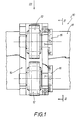
- Fig. 1 shows a top view in sections of a device 10 for attaching an embossing foil impression on a flexible material web, the illustration of the heatable embossing roller having been omitted in order to illustrate a pair of pressure rollers 12 which are parallel to one another on a bearing block 14 are rotatably mounted.
- Each pressure roller 12 can be adjusted as desired by means of an adjusting device 16 in relation to the embossing roller (not shown) of the device 10.
- the bearing block 14 is arranged linearly adjustable along a sectionally drawn support bracket 18.
- FIG. 2 illustrates the cross-sectional profile of the support bracket 18 on which the bearing block 14 for the two pressure rollers 12 is arranged in a linear manner.
- the reference number 16 in this figure also denotes the scaled setting devices for the pressure rollers 12.
- the Pressure rollers 12 can be adjusted as desired in relation to the heatable embossing roller 20, which is drawn in sections in FIG. 2. Due to the desired adjustment of the pressure rollers 12 relative to the embossing roller 20, a defined setting of the distance of the corresponding pressure roller 12 relative to the embossing roller 20 and thus a defined setting of the embossing film and material web to be embossed (not shown) between the embossing roller 20 and the pressure rollers 12 exerted pressure possible.
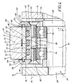
- Fig. 3 shows a side view in sections of the support bracket 18 on which the bearing block 14 for a pair of pressure rollers 12 is linearly adjustable.
- a screw element 22 see also FIG. 2
- a bearing axis 26 is mounted on the bearing block 14 between two spaced apart bearing legs 24, which has an eccentric section 30 between two coaxial bearing sections 28.
- the eccentric section 30 has an eccentricity e with respect to the two lateral bearing sections 28.
- the / each pressure roller 12 has an inner bush 32 which is rotatably mounted on the eccentric section 30 of the bearing axis 26 by means of bearing devices 34, which are, for example, ball bearings.
- the bearing devices 34 are defined on one another by means of a spacer ring 36 Kept clear.
- the inner sleeve 32 is formed on its outer circumferential surface 38 with circumferential recesses 40 spaced apart from one another, which are provided for receiving an associated annular compensating element 42 made of an elastically resilient material of defined hardness.
- the inner sleeve 32 is surrounded concentrically by an outer sleeve 44 which has an inner sleeve 46 and an outer sleeve 48.
- the inner sleeve 46 consists for example of a metal or a metal alloy, while the outer sleeve 48 e.g. or the like from a phenolic resin molding compound. consists. Inner and outer sleeves 46 and 48 are glued and / or pressed together.
- the inner diameter of the outer sleeve 44 or the inner sleeve 46 of the outer sleeve 44 is slightly larger than the outer diameter of the inner sleeve 32, so that there is a gap 52 between the outer jacket surface 38 of the inner sleeve 32 and the inner jacket surface 50 of the outer sleeve 44.
- This gap space 52 is bridged by the elastically flexible annular compensation elements 42, which press against both the inner sleeve 32 and the outer sleeve 44.
- the outer lateral surface 54 of the outer bush 44 or the outer sleeve 48 is the outer bush 44 beveled at their two edge sections 56 at a small angle.
- An annular cover element 58 is fastened by means of screws 60 to each side surface of the corresponding pressure roller 12 in order to seal the gap 52 between the inner and outer bushings 32, 44 in a sealed manner.
- Each cover element 58 is formed on its inner side 62 with an encircling circular groove 64 in which an annular sealing element 66 is arranged.
- Each sealing element 66 lies not only on the associated annular cover element 58, but also also on the outer bush 44 of the corresponding pressure roller 12, so that access to the gap space 52 between the inner and outer bushes 32, 44 is sealed with the aid of the corresponding sealing element 66.
- the two sealing elements 66 permit limited axial mobility of the outer bush 44 relative to the associated inner bush 32 of the corresponding pressure roller 12.
- the inner bush 32 is axially wider than the outer bush 44 or the inner and outer sleeves 46, 48 of said outer bush 44, so that between each cover element 58 and associated outer bush 44 a play or Gap space 68 is present. From this figure, three compensating elements 42 can be seen, which are axially spaced apart. Through such a design with a plurality of compensating elements 42, the outer bush 44 or the inner and outer sleeves 46, 48 can not only radially spring axially parallel, but it is also to a small extent a differentiated, ie wobbling springs of the outer bush 44 or the inner and Outer socket 46, 48 possible. This has a positive effect, for example, for papers to be decorated that have a watermark.
Landscapes
- Engineering & Computer Science (AREA)
- Mechanical Engineering (AREA)
- General Engineering & Computer Science (AREA)
- Shaping Of Tube Ends By Bending Or Straightening (AREA)
- Machines For Manufacturing Corrugated Board In Mechanical Paper-Making Processes (AREA)
- Registering, Tensioning, Guiding Webs, And Rollers Therefor (AREA)
- Coating Apparatus (AREA)
- Treatment Of Fiber Materials (AREA)
- Toys (AREA)
Applications Claiming Priority (2)
| Application Number | Priority Date | Filing Date | Title |
|---|---|---|---|
| DE4226003 | 1992-08-06 | ||
| DE4226003A DE4226003C1 (fr) | 1992-08-06 | 1992-08-06 |
Publications (2)
| Publication Number | Publication Date |
|---|---|
| EP0582178A1 true EP0582178A1 (fr) | 1994-02-09 |
| EP0582178B1 EP0582178B1 (fr) | 1996-11-20 |
Family
ID=6464971
Family Applications (1)
| Application Number | Title | Priority Date | Filing Date |
|---|---|---|---|
| EP19930111973 Expired - Lifetime EP0582178B1 (fr) | 1992-08-06 | 1993-07-28 | Dispositif pour appliquer une reproduction de feuille à gaufrer sur une bande flexibile |
Country Status (7)
| Country | Link |
|---|---|
| US (1) | US5368680A (fr) |
| EP (1) | EP0582178B1 (fr) |
| JP (1) | JP2550471B2 (fr) |
| AT (1) | ATE145454T1 (fr) |
| DE (1) | DE4226003C1 (fr) |
| DK (1) | DK0582178T3 (fr) |
| ES (1) | ES2094970T3 (fr) |
Cited By (9)
| Publication number | Priority date | Publication date | Assignee | Title |
|---|---|---|---|---|
| CH656575A5 (en) * | 1984-06-14 | 1986-07-15 | Swiss Cab E A Schoen S A | Extruder head for wire or cable jackets |
| EP0703338A1 (fr) * | 1994-09-22 | 1996-03-27 | Inventio Ag | Rouleau pour porte coulissante |
| WO2010108609A1 (fr) | 2009-03-27 | 2010-09-30 | Ab Skf | Agencement de palier pour un rouleau d'appui |
| EP3165366A1 (fr) | 2015-11-05 | 2017-05-10 | KBA-NotaSys SA | Presse d'estampage alimentée en feuilles avec unité de laminage d'une feuille |
| EP3165365A1 (fr) | 2015-11-05 | 2017-05-10 | KBA-NotaSys SA | Presse d'estampage alimentée en feuilles comprenant une unité de laminage d'une feuille |
| EP3173232A1 (fr) | 2015-11-30 | 2017-05-31 | KBA-NotaSys SA | Presse à estamper à chaud |
| DE102019111857A1 (de) * | 2019-05-07 | 2020-11-12 | Koenig & Bauer Ag | Heißprägepresse |
| DE102019111858A1 (de) * | 2019-05-07 | 2020-11-12 | Koenig & Bauer Ag | Heißprägepresse |
| CN115053077A (zh) * | 2020-02-20 | 2022-09-13 | 松下知识产权经营株式会社 | 轴承结构 |
Families Citing this family (7)
| Publication number | Priority date | Publication date | Assignee | Title |
|---|---|---|---|---|
| US6387201B1 (en) * | 1999-05-14 | 2002-05-14 | Best Cutting Die Company | Rotary hot foil stamping machine |
| DE10036292A1 (de) * | 2000-07-26 | 2002-02-07 | Jagenberg Papiertech Gmbh | Prägevorrichtung zur Erzeugung einer Haftung zwischen Lagen aus Tissue-Material |
| DE10128863A1 (de) * | 2001-06-15 | 2002-12-19 | Ina Schaeffler Kg | Anordnung zum Lagern einer Biegerolle |
| FR2865965B1 (fr) | 2004-02-10 | 2007-11-30 | Cebal Sas | Procede permettant de decorer en grande cadence des recipients a paroi cylindrique |
| DE102004028524B4 (de) * | 2004-06-11 | 2007-06-06 | Leonhard Kurz Gmbh & Co. Kg | Vorrichtung zum Anbringen mindestens eines Flächenabschnitts einer Übertragungslage einer Transferfolie auf einer Materialbahn und deren Verwendung |
| ES2346269T3 (es) * | 2008-02-05 | 2010-10-13 | Texmag Gmbh Vertriebsgesellschaft | Cilindro para ejercer una presion de contacto sobre bandas de material. |
| US8821149B2 (en) * | 2011-05-05 | 2014-09-02 | Kimberly-Clark Worldwide, Inc. | Web treatment apparatus having center bearer ring |
Citations (8)
| Publication number | Priority date | Publication date | Assignee | Title |
|---|---|---|---|---|
| US2803507A (en) * | 1952-12-03 | 1957-08-20 | Licentia Gmbh | Resilient spacer rings for multiple bearings rotatably supporting shafts |
| US2825439A (en) * | 1956-11-05 | 1958-03-04 | Collis & Sons Ltd J | Bearings for roller conveyors |
| US3362760A (en) * | 1964-07-03 | 1968-01-09 | Sernetz Heinz | Roller construction particularly for conveyors |
| US3431035A (en) * | 1966-06-21 | 1969-03-04 | Ind Et Commerciale Des Automob | Flexible bearing in particular for an automobile vehicle suspension |
| FR2137579A1 (fr) * | 1971-05-07 | 1972-12-29 | Smith & Nephew Res | |
| FR2349762A1 (fr) * | 1976-04-28 | 1977-11-25 | Eisbein Develop | Cylindre de pression, notamment pour machines a copier |
| DE2834979A1 (de) * | 1978-08-10 | 1980-02-21 | Schaeffler Ohg Industriewerk | Waelzgelagerte rolle |
| EP0469433A1 (fr) * | 1990-08-02 | 1992-02-05 | Leonhard Kurz Gmbh & Co. | Dispositif pour appliquer une reproduction de feuille gainée sur une voie en matériel flexible |
Family Cites Families (12)
| Publication number | Priority date | Publication date | Assignee | Title |
|---|---|---|---|---|
| US3840420A (en) * | 1972-05-31 | 1974-10-08 | Seal | Laminating apparatus |
| DE2251763C3 (de) * | 1972-10-21 | 1975-06-05 | Hermann Berstorff Maschinenbau Gmbh, 3000 Hannover | Walze mit Durchbiegungsausgleich zum Auswalzen von plastischen Werkstoffen zu Folienbahnen auf einem Kalander oder Walzwerk |
| JPS5531321B2 (fr) * | 1973-07-13 | 1980-08-18 | ||
| SU563447A1 (ru) * | 1976-01-16 | 1977-06-30 | Ленинградский технологический институт целлюлозно-бумажной промышленности | Малопрогибаемый вал |
| UST981004I4 (en) * | 1978-04-10 | 1979-04-03 | Caterpillar Tractor Co. | Resiliently mounted wheel assembly |
| DE3210551C2 (de) * | 1982-03-23 | 1984-11-08 | Fa. Leonhard Kurz, 8510 Fürth | Verfahren und Vorrichtung zum Anbringen eines Prägefolien-Abdruckes auf einer flexiblen Materialbahn |
| FI80307C (fi) * | 1986-02-21 | 1990-05-10 | Tampella Oy Ab | Pressvals. |
| JPS62278038A (ja) * | 1986-05-28 | 1987-12-02 | Yoshida Kogyo Kk <Ykk> | 熱転写装置 |
| DE8805783U1 (de) * | 1988-05-02 | 1988-06-16 | Pfaff Industriemaschinen Gmbh, 6750 Kaiserslautern | Vorrichtung zum Verschweißen von Kunststoffolien |
| US5209283A (en) * | 1988-07-08 | 1993-05-11 | Mannesmann Ag | Roll and/or roller for machines of continuous casting |
| DE3915508A1 (de) * | 1989-05-12 | 1990-11-15 | Feldmuehle Ag | Walze zur druckbehandlung von warenbahnen |
| US4975153A (en) * | 1989-08-23 | 1990-12-04 | Beloit Corporation | Press section apparatus with deflection compensated granite roll shell |
-
1992
- 1992-08-06 DE DE4226003A patent/DE4226003C1/de not_active Expired - Fee Related
-
1993
- 1993-06-30 US US08/085,609 patent/US5368680A/en not_active Expired - Lifetime
- 1993-07-22 JP JP18105893A patent/JP2550471B2/ja not_active Expired - Lifetime
- 1993-07-28 AT AT93111973T patent/ATE145454T1/de not_active IP Right Cessation
- 1993-07-28 DK DK93111973T patent/DK0582178T3/da active
- 1993-07-28 ES ES93111973T patent/ES2094970T3/es not_active Expired - Lifetime
- 1993-07-28 EP EP19930111973 patent/EP0582178B1/fr not_active Expired - Lifetime
Patent Citations (8)
| Publication number | Priority date | Publication date | Assignee | Title |
|---|---|---|---|---|
| US2803507A (en) * | 1952-12-03 | 1957-08-20 | Licentia Gmbh | Resilient spacer rings for multiple bearings rotatably supporting shafts |
| US2825439A (en) * | 1956-11-05 | 1958-03-04 | Collis & Sons Ltd J | Bearings for roller conveyors |
| US3362760A (en) * | 1964-07-03 | 1968-01-09 | Sernetz Heinz | Roller construction particularly for conveyors |
| US3431035A (en) * | 1966-06-21 | 1969-03-04 | Ind Et Commerciale Des Automob | Flexible bearing in particular for an automobile vehicle suspension |
| FR2137579A1 (fr) * | 1971-05-07 | 1972-12-29 | Smith & Nephew Res | |
| FR2349762A1 (fr) * | 1976-04-28 | 1977-11-25 | Eisbein Develop | Cylindre de pression, notamment pour machines a copier |
| DE2834979A1 (de) * | 1978-08-10 | 1980-02-21 | Schaeffler Ohg Industriewerk | Waelzgelagerte rolle |
| EP0469433A1 (fr) * | 1990-08-02 | 1992-02-05 | Leonhard Kurz Gmbh & Co. | Dispositif pour appliquer une reproduction de feuille gainée sur une voie en matériel flexible |
Non-Patent Citations (1)
| Title |
|---|
| US-I-T981004 (R. T. MC NEELY ET AL.) * |
Cited By (19)
| Publication number | Priority date | Publication date | Assignee | Title |
|---|---|---|---|---|
| CH656575A5 (en) * | 1984-06-14 | 1986-07-15 | Swiss Cab E A Schoen S A | Extruder head for wire or cable jackets |
| EP0703338A1 (fr) * | 1994-09-22 | 1996-03-27 | Inventio Ag | Rouleau pour porte coulissante |
| WO2010108609A1 (fr) | 2009-03-27 | 2010-09-30 | Ab Skf | Agencement de palier pour un rouleau d'appui |
| US10737485B2 (en) | 2015-11-05 | 2020-08-11 | Kba-Notasys Sa | Sheet-fed stamping press comprising a foil laminating unit |
| EP3165366A1 (fr) | 2015-11-05 | 2017-05-10 | KBA-NotaSys SA | Presse d'estampage alimentée en feuilles avec unité de laminage d'une feuille |
| EP3165365A1 (fr) | 2015-11-05 | 2017-05-10 | KBA-NotaSys SA | Presse d'estampage alimentée en feuilles comprenant une unité de laminage d'une feuille |
| WO2017077477A1 (fr) | 2015-11-05 | 2017-05-11 | Kba-Notasys Sa | Presse à estamper alimentée en feuilles comprenant une unité de stratification de matériau en pellicule |
| WO2017077478A1 (fr) | 2015-11-05 | 2017-05-11 | Kba-Notasys Sa | Presse à gaufrer d'acheminement de feuille ayant une unité de stratification de feuille |
| US11065865B2 (en) | 2015-11-05 | 2021-07-20 | Kba-Notasys Sa | Sheet-fed stamping press having a foil laminating unit |
| CN108136767A (zh) * | 2015-11-05 | 2018-06-08 | 卡巴-诺塔赛斯有限公司 | 具有箔层压单元的单张纸压印机 |
| CN108349238A (zh) * | 2015-11-05 | 2018-07-31 | 卡巴-诺塔赛斯有限公司 | 包括箔层压单元的单张纸压印机 |
| WO2017093894A1 (fr) | 2015-11-30 | 2017-06-08 | Kba-Notasys Sa | Presse à marquer à chaud |
| EP3173232A1 (fr) | 2015-11-30 | 2017-05-31 | KBA-NotaSys SA | Presse à estamper à chaud |
| US11697277B2 (en) | 2015-11-30 | 2023-07-11 | Kba-Notsys Sa | Hot-stamping press |
| DE102019111857A1 (de) * | 2019-05-07 | 2020-11-12 | Koenig & Bauer Ag | Heißprägepresse |
| DE102019111858A1 (de) * | 2019-05-07 | 2020-11-12 | Koenig & Bauer Ag | Heißprägepresse |
| DE102019111857B4 (de) | 2019-05-07 | 2022-05-25 | Koenig & Bauer Ag | Heißprägepresse |
| DE102019111858B4 (de) | 2019-05-07 | 2022-05-25 | Koenig & Bauer Ag | Heißprägepresse |
| CN115053077A (zh) * | 2020-02-20 | 2022-09-13 | 松下知识产权经营株式会社 | 轴承结构 |
Also Published As
| Publication number | Publication date |
|---|---|
| EP0582178B1 (fr) | 1996-11-20 |
| ATE145454T1 (de) | 1996-12-15 |
| HK1005890A1 (en) | 1999-01-29 |
| ES2094970T3 (es) | 1997-02-01 |
| JPH06166168A (ja) | 1994-06-14 |
| DE4226003C1 (fr) | 1993-06-24 |
| US5368680A (en) | 1994-11-29 |
| JP2550471B2 (ja) | 1996-11-06 |
| DK0582178T3 (da) | 1996-12-09 |
Similar Documents
| Publication | Publication Date | Title |
|---|---|---|
| EP0582178B1 (fr) | Dispositif pour appliquer une reproduction de feuille à gaufrer sur une bande flexibile | |
| DE69016358T2 (de) | Verfahren zum Montieren von Wellenlagern, insbesondere in Drehgebern, Montiervorrichtung dafür und erzielte Drehgeber. | |
| EP1122471B1 (fr) | Agencement d'étanchéité entre deux éléments en rotation l'un par rapport à l'autre | |
| DE102007002785B4 (de) | Rotationssymmetrischer Körper mit einer Spannvorrichtung zur Befestigung von plattenförmigen Gegenständen | |
| EP0570786B1 (fr) | Transformateur rotatif pour machines à imprimer | |
| DE2939560C2 (de) | Festlager mit einem Wälzlager, insbesondere für die Lagerung der Läuferwelle eines kleineren Elektromotors | |
| EP0540964A1 (fr) | Support pour couteau circulaire pour machines de traitement du papier | |
| EP1840242B1 (fr) | Dispositif de transport sous vide avec un rail de guidage déplaçable | |
| EP3027926B2 (fr) | Frein à disque, notamment pour véhicules utilitaires, et plaquette de frein d'un tel frein à disque | |
| DE2463077C2 (de) | Endschalter | |
| WO1998019076A1 (fr) | Frein a disque | |
| EP1014044A1 (fr) | Dispositif à centrage automatique d'un moyeu d'un disque de codeur et son procédé de montage | |
| DE2636444B2 (de) | Führung des zweigeteilten Sattels einer Schwimmsattel-Teilbelag-Scheibenbremse | |
| EP0705690B1 (fr) | Rouleau de guidage de feuilles avec un diamètre extérieur réglable | |
| DE2720673B2 (de) | Vorrichtung zum ungleichförmigen Spannen eines Gummituches in einer Offsetdruckmaschine | |
| DE4344365A1 (de) | Druckwerk für eine Rotationsdruckmaschine | |
| EP0422625B1 (fr) | Rouleau applicateur à mouvement de va-et-vient dans un dispositif d'encrage de machine d'impression | |
| DE3033302C2 (fr) | ||
| EP1572461A1 (fr) | Ensemble blanchet pour cylindre a blanchet et son procede de production | |
| AT522181B1 (de) | Dichtungsanordnung | |
| DE3721757C2 (fr) | ||
| DE102004050443B4 (de) | Vorrichtung zum Rotationsstanzen, Umrüstsatz für eine Vorrichtung zum Rotationsstanzen und Verfahren zum Umrüsten | |
| DE102007057188A1 (de) | Stanzvorrichtung und Gegenstanzzylinder für eine Stanzvorrichtung | |
| DE102004032030A1 (de) | Vorrichtung zum Stanzen und/oder Prägen von Materialbahnen | |
| DE3434642C1 (de) | Stoßfreie Druckplatten- und Gummituchspannvorrichtung an Druckwerkszylindern von Rotationsdruckmaschinen |
Legal Events
| Date | Code | Title | Description |
|---|---|---|---|
| PUAI | Public reference made under article 153(3) epc to a published international application that has entered the european phase |
Free format text: ORIGINAL CODE: 0009012 |
|
| AK | Designated contracting states |
Kind code of ref document: A1 Designated state(s): AT BE CH DE DK ES FR GB IT LI LU NL SE |
|
| RTI1 | Title (correction) | ||
| 17P | Request for examination filed |
Effective date: 19940806 |
|
| GRAG | Despatch of communication of intention to grant |
Free format text: ORIGINAL CODE: EPIDOS AGRA |
|
| 17Q | First examination report despatched |
Effective date: 19960312 |
|
| GRAH | Despatch of communication of intention to grant a patent |
Free format text: ORIGINAL CODE: EPIDOS IGRA |
|
| GRAH | Despatch of communication of intention to grant a patent |
Free format text: ORIGINAL CODE: EPIDOS IGRA |
|
| RBV | Designated contracting states (corrected) |
Designated state(s): AT BE CH DK ES FR GB IT LI LU NL SE |
|
| GRAA | (expected) grant |
Free format text: ORIGINAL CODE: 0009210 |
|
| REG | Reference to a national code |
Ref country code: DE Ref legal event code: 8566 |
|
| AK | Designated contracting states |
Kind code of ref document: B1 Designated state(s): AT BE CH DK ES FR GB IT LI LU NL SE |
|
| REF | Corresponds to: |
Ref document number: 145454 Country of ref document: AT Date of ref document: 19961215 Kind code of ref document: T |
|
| REG | Reference to a national code |
Ref country code: CH Ref legal event code: NV Representative=s name: FIAMMENGHI-FIAMMENGHI |
|
| REG | Reference to a national code |
Ref country code: DK Ref legal event code: T3 |
|
| REG | Reference to a national code |
Ref country code: ES Ref legal event code: FG2A Ref document number: 2094970 Country of ref document: ES Kind code of ref document: T3 |
|
| ITF | It: translation for a ep patent filed | ||
| ET | Fr: translation filed | ||
| GBT | Gb: translation of ep patent filed (gb section 77(6)(a)/1977) |
Effective date: 19970124 |
|
| PG25 | Lapsed in a contracting state [announced via postgrant information from national office to epo] |
Ref country code: DK Free format text: LAPSE BECAUSE OF NON-PAYMENT OF DUE FEES Effective date: 19970728 |
|
| REG | Reference to a national code |
Ref country code: DK Ref legal event code: EBP |
|
| PG25 | Lapsed in a contracting state [announced via postgrant information from national office to epo] |
Ref country code: LU Free format text: LAPSE BECAUSE OF NON-PAYMENT OF DUE FEES Effective date: 19970731 Ref country code: BE Free format text: LAPSE BECAUSE OF NON-PAYMENT OF DUE FEES Effective date: 19970731 |
|
| PLBE | No opposition filed within time limit |
Free format text: ORIGINAL CODE: 0009261 |
|
| STAA | Information on the status of an ep patent application or granted ep patent |
Free format text: STATUS: NO OPPOSITION FILED WITHIN TIME LIMIT |
|
| 26N | No opposition filed | ||
| BERE | Be: lapsed |
Owner name: LEONHARD KURZ G.M.B.H. & CO. Effective date: 19970731 |
|
| PG25 | Lapsed in a contracting state [announced via postgrant information from national office to epo] |
Ref country code: NL Free format text: LAPSE BECAUSE OF NON-PAYMENT OF DUE FEES Effective date: 19980201 |
|
| NLV4 | Nl: lapsed or anulled due to non-payment of the annual fee |
Effective date: 19980201 |
|
| PGFP | Annual fee paid to national office [announced via postgrant information from national office to epo] |
Ref country code: SE Payment date: 20010723 Year of fee payment: 9 |
|
| PGFP | Annual fee paid to national office [announced via postgrant information from national office to epo] |
Ref country code: ES Payment date: 20010730 Year of fee payment: 9 Ref country code: AT Payment date: 20010730 Year of fee payment: 9 |
|
| REG | Reference to a national code |
Ref country code: GB Ref legal event code: IF02 |
|
| PG25 | Lapsed in a contracting state [announced via postgrant information from national office to epo] |
Ref country code: AT Free format text: LAPSE BECAUSE OF NON-PAYMENT OF DUE FEES Effective date: 20020728 |
|
| PG25 | Lapsed in a contracting state [announced via postgrant information from national office to epo] |
Ref country code: SE Free format text: LAPSE BECAUSE OF NON-PAYMENT OF DUE FEES Effective date: 20020729 Ref country code: ES Free format text: LAPSE BECAUSE OF NON-PAYMENT OF DUE FEES Effective date: 20020729 |
|
| EUG | Se: european patent has lapsed | ||
| REG | Reference to a national code |
Ref country code: ES Ref legal event code: FD2A Effective date: 20030811 |
|
| PGFP | Annual fee paid to national office [announced via postgrant information from national office to epo] |
Ref country code: CH Payment date: 20110725 Year of fee payment: 19 Ref country code: FR Payment date: 20110729 Year of fee payment: 19 |
|
| PGFP | Annual fee paid to national office [announced via postgrant information from national office to epo] |
Ref country code: GB Payment date: 20110721 Year of fee payment: 19 |
|
| PGFP | Annual fee paid to national office [announced via postgrant information from national office to epo] |
Ref country code: IT Payment date: 20110726 Year of fee payment: 19 |
|
| REG | Reference to a national code |
Ref country code: CH Ref legal event code: PL |
|
| GBPC | Gb: european patent ceased through non-payment of renewal fee |
Effective date: 20120728 |
|
| REG | Reference to a national code |
Ref country code: FR Ref legal event code: ST Effective date: 20130329 |
|
| PG25 | Lapsed in a contracting state [announced via postgrant information from national office to epo] |
Ref country code: GB Free format text: LAPSE BECAUSE OF NON-PAYMENT OF DUE FEES Effective date: 20120728 Ref country code: FR Free format text: LAPSE BECAUSE OF NON-PAYMENT OF DUE FEES Effective date: 20120731 Ref country code: LI Free format text: LAPSE BECAUSE OF NON-PAYMENT OF DUE FEES Effective date: 20120731 Ref country code: CH Free format text: LAPSE BECAUSE OF NON-PAYMENT OF DUE FEES Effective date: 20120731 |
|
| PG25 | Lapsed in a contracting state [announced via postgrant information from national office to epo] |
Ref country code: IT Free format text: LAPSE BECAUSE OF NON-PAYMENT OF DUE FEES Effective date: 20120728 |