EP0582437A2 - Test zur Bestimmung der Haftfestigkeit - Google Patents
Test zur Bestimmung der Haftfestigkeit Download PDFInfo
- Publication number
- EP0582437A2 EP0582437A2 EP93305988A EP93305988A EP0582437A2 EP 0582437 A2 EP0582437 A2 EP 0582437A2 EP 93305988 A EP93305988 A EP 93305988A EP 93305988 A EP93305988 A EP 93305988A EP 0582437 A2 EP0582437 A2 EP 0582437A2
- Authority
- EP
- European Patent Office
- Prior art keywords
- component
- bond
- sample
- force
- components
- Prior art date
- Legal status (The legal status is an assumption and is not a legal conclusion. Google has not performed a legal analysis and makes no representation as to the accuracy of the status listed.)
- Withdrawn
Links
- 238000012360 testing method Methods 0.000 title claims abstract description 24
- 238000000034 method Methods 0.000 claims abstract description 11
- 238000003754 machining Methods 0.000 claims description 4
- 238000010998 test method Methods 0.000 claims description 2
- 210000000988 bone and bone Anatomy 0.000 description 1
- 230000007547 defect Effects 0.000 description 1
- 238000012986 modification Methods 0.000 description 1
- 230000004048 modification Effects 0.000 description 1
Images

Classifications
-
- G—PHYSICS
- G01—MEASURING; TESTING
- G01N—INVESTIGATING OR ANALYSING MATERIALS BY DETERMINING THEIR CHEMICAL OR PHYSICAL PROPERTIES
- G01N3/00—Investigating strength properties of solid materials by application of mechanical stress
-
- G—PHYSICS
- G01—MEASURING; TESTING
- G01N—INVESTIGATING OR ANALYSING MATERIALS BY DETERMINING THEIR CHEMICAL OR PHYSICAL PROPERTIES
- G01N19/00—Investigating materials by mechanical methods
- G01N19/04—Measuring adhesive force between materials, e.g. of sealing tape, of coating
-
- G—PHYSICS
- G01—MEASURING; TESTING
- G01N—INVESTIGATING OR ANALYSING MATERIALS BY DETERMINING THEIR CHEMICAL OR PHYSICAL PROPERTIES
- G01N2203/00—Investigating strength properties of solid materials by application of mechanical stress
- G01N2203/02—Details not specific for a particular testing method
- G01N2203/026—Specifications of the specimen
- G01N2203/0262—Shape of the specimen
- G01N2203/0274—Tubular or ring-shaped specimens
-
- G—PHYSICS
- G01—MEASURING; TESTING
- G01N—INVESTIGATING OR ANALYSING MATERIALS BY DETERMINING THEIR CHEMICAL OR PHYSICAL PROPERTIES
- G01N2203/00—Investigating strength properties of solid materials by application of mechanical stress
- G01N2203/02—Details not specific for a particular testing method
- G01N2203/026—Specifications of the specimen
- G01N2203/0296—Welds
Definitions
- the present invention relates to the testing of the lap strength of a bond between two components.
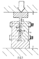
- Figure 1 shows a conventional test rig for testing the lap shear strength of a bond between two components.
- a sample 3 is prepared for testing and is composed of two components 3a and 3b, joined together in an overlapping region by a bond 5, whose strength is to be tested.
- the sample may be made by joining components 3a and 3b along their entire adjacent surfaces and machining away parts of the respective components on either side of the bond as shown in Figure 1.
- the sample 3 is then placed in a channel 1 so that it sits on a push member 23 which engages only component 3a.
- a further push member 4 engages component 3b and the test rig is placed between the platens 6 and 7 of a press, which compresses the sample 3 between the push members 2 and 4 so that a force is applied along the line of the bond until the bond fails.
- the force exerted by the press at the point of failure is recorded as the lap shear strength of the bond.
- One disadvantage of the process described is that it is insensitive to bond line defects, especially if the bone line is not straight.
- Another disadvantage of the described process lies in the fact that the push members 2 and 4 exert a turning moment on the sample 3. The sample cannot move under this moment because the sample is located in channel 1 but it causes frictional forces between the sample 3 and the channel 2 which leads to inaccuracies.
- the present invention is intended to overcome the above problems and provide a method and apparatus for accurately testing the strength of a bond between two components.
- a method of testing the strength of a bond between a first component and a second component comprises: forming an opening in the first component (if not already present) whereby the second component can be engaged via the opening, engaging the second component via the said opening, engaging the first component, exerting an increasing force between the engagement locations of the two components that applies tension to the bond and is exerted in a direction substantially perpendicular to the plane of the bond, and recording the force exerted when the bond fails.
- the first component extends beyond the second component (optimally around the whole circumference of the second component) so that the first component can be engaged by means of the said extended portion, e.g. by placing a sample composed of the first and second component into a jig that includes an opening of a shape corresponding to the shape of the sample but which is slightly smaller than the sample so that the extended portion of the first component rests on the edge of a cavity.
- the sample is symmetrical about the opening in the first component (and most preferably is circular).
- test sample and a test rig for testing the strength of a bond between components in the sample is shown, by way of example only, with reference to Figures 2 to 6 in which:
- two components 12, 14 are joined together by means of a substantially plane bond 16, which is the bond that is to be tested.
- the bonded components are then machined to form the sample 10 shown in Figure 5 by forming a relatively large circular central opening 18 in the first component 12, a narrow bore 20 in the second component 14 and by machining away the underside of the second component 14 to provide an annular overhanging region 22 of the first component 12.
- the overhanging region 22 extends around the entire periphery of the sample 10.
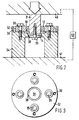
- the sample 10 is circular in plan and is symmetrical about the opening 18 (as can be seen in Figure 6).
- a rig for testing the samples of Figures 5 and 6 is shown in Figures 2 and 3 and comprises a base 34 having a central opening 38 of circular shape, the opening having a diameter larger than that of the second component 14 but smaller than that of the overhanging region 22 of the first component 12.
- the sample 10 is located with the overhanging region 22 of the first component 12 seated on the base 34 and with the second component 14 disposed within the opening 38.
- the sample 10 is then clamped in place around its periphery by means of an annular ring 32, which engages the first component 12 and is secured by bolts 35 passing through the ring into the base 34.
- Pins 36 limit the movement of ring 32 and hence the clamping force that can be exerted on sample 10.
- the second component 14 of the sample 10 is secured to a ram 31 by means of a bolt 39 that passes through the bore 20 and that has a screw thread engaging in the ram 31.
- test rig is then placed between the platens 40 and 41 of a press and the ram 31 is urged downwardly with increasing force until the bond 16 in the sample 10 fails.
- the loading force at the time of failure is recorded, by means of measuring apparatus 50 shown schematically only, as the tensile strength of the bond.
- sample it is possible for the sample to be other than circular, and for the bonded surfaces of the first and second components to be slightly dished, for example, as opposed to completely flat.
Landscapes
- Physics & Mathematics (AREA)
- Health & Medical Sciences (AREA)
- Life Sciences & Earth Sciences (AREA)
- Chemical & Material Sciences (AREA)
- Analytical Chemistry (AREA)
- Biochemistry (AREA)
- General Health & Medical Sciences (AREA)
- General Physics & Mathematics (AREA)
- Immunology (AREA)
- Pathology (AREA)
- Investigating Strength Of Materials By Application Of Mechanical Stress (AREA)
Applications Claiming Priority (2)
| Application Number | Priority Date | Filing Date | Title |
|---|---|---|---|
| GB929216856A GB9216856D0 (en) | 1992-08-07 | 1992-08-07 | Test for bond strength |
| GB9216856 | 1992-08-07 |
Publications (2)
| Publication Number | Publication Date |
|---|---|
| EP0582437A2 true EP0582437A2 (de) | 1994-02-09 |
| EP0582437A3 EP0582437A3 (en) | 1994-05-18 |
Family
ID=10720036
Family Applications (1)
| Application Number | Title | Priority Date | Filing Date |
|---|---|---|---|
| EP19930305988 Withdrawn EP0582437A3 (en) | 1992-08-07 | 1993-07-28 | Test for bond strength |
Country Status (2)
| Country | Link |
|---|---|
| EP (1) | EP0582437A3 (de) |
| GB (1) | GB9216856D0 (de) |
Cited By (6)
| Publication number | Priority date | Publication date | Assignee | Title |
|---|---|---|---|---|
| DE4435579A1 (de) * | 1994-10-05 | 1996-04-11 | Orga Kartensysteme Gmbh | Verfahren zur Prüfung der Klebehaftung von Trägerelementen mit IC-Bausteinen in Chipkarten und Vorrichtung zur Durchführung dieses Verfahrens |
| WO2004023111A1 (en) * | 2002-09-09 | 2004-03-18 | Singapore Institute Of Manufacturing Technology | Apparatus and method for bonding strength testing |
| US6813958B2 (en) | 2001-06-21 | 2004-11-09 | The United States Of America As Represented By The Secretary Of Commerce | Method for combinatorially measuring adhesion strength |
| DE102005060573A1 (de) * | 2005-12-17 | 2007-06-28 | Universität Kassel | Vorrichtung und Verfahren zur Bestimmung des mechanischen Verhaltens eines Klebstoffes |
| US20160258862A1 (en) * | 2015-03-02 | 2016-09-08 | SK Hynix Inc. | Method of measuring an adhesive force of interlayer adhesive layer in tensile mode for stacked semiconductor device and apparatus for measuring the same |
| WO2020087102A1 (en) * | 2018-10-31 | 2020-05-07 | Technische Universität Wien | Method and means for testing the strength of a bonding between two specimen elements |
Family Cites Families (7)
| Publication number | Priority date | Publication date | Assignee | Title |
|---|---|---|---|---|
| DE698709C (de) * | 1938-08-13 | 1940-11-15 | Kohle Und Eisenforschung G M B | Verfahren zum Pruefen der Haftfestigkeit der Plattierung auf plattierten Blechen |
| DE1103641B (de) * | 1958-09-15 | 1961-03-30 | Ernst Franke Dr Ing | Verfahren und Vorrichtung zum Ermitteln des Haftvermoegens von Schichten beliebigen festen Stoffes auf Koerpern (Grundschichten) beliebiger Gestalt und beliebigen festenStoffes |
| US4282759A (en) * | 1979-12-26 | 1981-08-11 | The United States Of America As Represented By The Secretary Of The Army | Method and apparatus for non-destructive testing of beam-lead integrated circuit connections |
| FR2570826B1 (fr) * | 1984-09-27 | 1987-12-18 | Exper Rech Etu Batimen Centre | Dispositif de mesure de la resistance a l'arrachement d'un materiau ou d'un composant mecanique de construction |
| DE3525068C1 (de) * | 1985-07-13 | 1986-05-28 | Kolbenschmidt AG, 7107 Neckarsulm | Verfahren zur Beurteilung des Haftens der aus Kunststoff bestehenden Gleitschicht von Mehrschicht-Gleitlagerwerkstoffen |
| US4876896A (en) * | 1986-06-16 | 1989-10-31 | I.W. Industries, Inc. | Method of testing protective encapsulation of structural members |
| US4899581A (en) * | 1988-02-19 | 1990-02-13 | Massachusetts Institute Of Technology | Method and apparatus for the quantitative measurement of adhesion of thin films |
-
1992
- 1992-08-07 GB GB929216856A patent/GB9216856D0/en active Pending
-
1993
- 1993-07-28 EP EP19930305988 patent/EP0582437A3/en not_active Withdrawn
Cited By (11)
| Publication number | Priority date | Publication date | Assignee | Title |
|---|---|---|---|---|
| DE4435579A1 (de) * | 1994-10-05 | 1996-04-11 | Orga Kartensysteme Gmbh | Verfahren zur Prüfung der Klebehaftung von Trägerelementen mit IC-Bausteinen in Chipkarten und Vorrichtung zur Durchführung dieses Verfahrens |
| US6813958B2 (en) | 2001-06-21 | 2004-11-09 | The United States Of America As Represented By The Secretary Of Commerce | Method for combinatorially measuring adhesion strength |
| WO2004023111A1 (en) * | 2002-09-09 | 2004-03-18 | Singapore Institute Of Manufacturing Technology | Apparatus and method for bonding strength testing |
| DE102005060573A1 (de) * | 2005-12-17 | 2007-06-28 | Universität Kassel | Vorrichtung und Verfahren zur Bestimmung des mechanischen Verhaltens eines Klebstoffes |
| US20160258862A1 (en) * | 2015-03-02 | 2016-09-08 | SK Hynix Inc. | Method of measuring an adhesive force of interlayer adhesive layer in tensile mode for stacked semiconductor device and apparatus for measuring the same |
| US9945772B2 (en) * | 2015-03-02 | 2018-04-17 | SK Hynix Inc. | Method of measuring an adhesive force of interlayer adhesive layer in tensile mode for stacked semiconductor device and apparatus for measuring the same |
| US10393646B2 (en) * | 2015-03-02 | 2019-08-27 | SK Hynix Inc. | Method of measuring an adhesive force of interlayer adhesive layer in tensile mode for stacked semiconductor device and apparatus for measuring the same |
| WO2020087102A1 (en) * | 2018-10-31 | 2020-05-07 | Technische Universität Wien | Method and means for testing the strength of a bonding between two specimen elements |
| AT521815A1 (de) * | 2018-10-31 | 2020-05-15 | Univ Wien Tech | Verfahren und Mittel zur Prüfung der Verbindungsfestigkeit zwischen zwei Probenelementen |
| US20210372896A1 (en) * | 2018-10-31 | 2021-12-02 | Technische Universitat Wien | Method and means for testing the strength of a bonding between two specimen elements |
| US12013375B2 (en) * | 2018-10-31 | 2024-06-18 | Technische Universitat Wien | Method and means for testing the strength of a bonding between two specimen elements |
Also Published As
| Publication number | Publication date |
|---|---|
| EP0582437A3 (en) | 1994-05-18 |
| GB9216856D0 (en) | 1992-09-23 |
Similar Documents
| Publication | Publication Date | Title |
|---|---|---|
| US5297441A (en) | Apparatus for supporting a test specimen for compression testing | |
| US5894981A (en) | Integrated pull tester with an ultrasonic wire bonder | |
| JPS63101732A (ja) | 材料試験用ロードフレームのグリップ | |
| EP2679980B1 (de) | System und Verfahren zum Testen einer Fillet-Bindung | |
| US3583238A (en) | Mechanism and method for mounting wheel on testing apparatus | |
| EP0582437A2 (de) | Test zur Bestimmung der Haftfestigkeit | |
| JP2735634B2 (ja) | 材料あるいは構造部品を試験するための突き刺し装置 | |
| US4934199A (en) | Method and apparatus for preparing specimens for destructive testing of graphite epoxy composite material | |
| GB2320332A (en) | Apparatus for the uniaxial investigation of microtensile samples | |
| MY105884A (en) | Method of an apparatus for applying top end stops on to a slide fastener chain. | |
| US4523710A (en) | Method for fabricating a fastener plate | |
| US4442705A (en) | Clamping nosepiece for hardness tester | |
| US5767414A (en) | Automatically aligning tool for uniformly applying a controlled force to an object | |
| US5685193A (en) | Disc brake pad assembly proof-testing | |
| US5696328A (en) | Self tightening clamp | |
| CN210401097U (zh) | 一种合成闸瓦剪切强度试验装置及用于该装置的工装 | |
| JPH0210245A (ja) | 材料の破壊強度測定装置 | |
| US3690161A (en) | Method and apparatus for testing thin webs in shear | |
| JPH1151833A (ja) | 引張試験用クランプ治具 | |
| JPH0658308B2 (ja) | 硬脆材料試験における試験片のチヤツキング方法 | |
| US20250327727A1 (en) | Tensile test fixture and alignment tool for testing soft polymeric foams | |
| JPH0194239A (ja) | 硬脆材料の試験における試験片のチャッキング方法 | |
| JPH01235830A (ja) | 硬脆材料試験における試験片の上部把み部のチャッキング方法 | |
| CN220751856U (zh) | 一种弯曲检测装置 | |
| CN214173970U (zh) | 短夹层螺栓拉伸试验装置 |
Legal Events
| Date | Code | Title | Description |
|---|---|---|---|
| PUAI | Public reference made under article 153(3) epc to a published international application that has entered the european phase |
Free format text: ORIGINAL CODE: 0009012 |
|
| AK | Designated contracting states |
Kind code of ref document: A2 Designated state(s): DE ES FR GB IT |
|
| PUAL | Search report despatched |
Free format text: ORIGINAL CODE: 0009013 |
|
| AK | Designated contracting states |
Kind code of ref document: A3 Designated state(s): DE ES FR GB IT |
|
| STAA | Information on the status of an ep patent application or granted ep patent |
Free format text: STATUS: THE APPLICATION IS DEEMED TO BE WITHDRAWN |
|
| 18D | Application deemed to be withdrawn |
Effective date: 19941119 |