EP0582802B1 - Dispositif pour la fabrication de câbles à sens de câblage alterné - Google Patents
Dispositif pour la fabrication de câbles à sens de câblage alterné Download PDFInfo
- Publication number
- EP0582802B1 EP0582802B1 EP93109183A EP93109183A EP0582802B1 EP 0582802 B1 EP0582802 B1 EP 0582802B1 EP 93109183 A EP93109183 A EP 93109183A EP 93109183 A EP93109183 A EP 93109183A EP 0582802 B1 EP0582802 B1 EP 0582802B1
- Authority
- EP
- European Patent Office
- Prior art keywords
- stranding
- disc
- elements
- guide
- guide disc
- Prior art date
- Legal status (The legal status is an assumption and is not a legal conclusion. Google has not performed a legal analysis and makes no representation as to the accuracy of the status listed.)
- Expired - Lifetime
Links
- 230000007423 decrease Effects 0.000 claims 1
- 230000002093 peripheral effect Effects 0.000 claims 1
- 239000004033 plastic Substances 0.000 description 4
- 239000000463 material Substances 0.000 description 3
- 210000003462 vein Anatomy 0.000 description 3
- 239000004952 Polyamide Substances 0.000 description 1
- 229910000831 Steel Inorganic materials 0.000 description 1
- 239000004760 aramid Substances 0.000 description 1
- 229920003235 aromatic polyamide Polymers 0.000 description 1
- 239000004020 conductor Substances 0.000 description 1
- 238000010924 continuous production Methods 0.000 description 1
- 238000010586 diagram Methods 0.000 description 1
- 238000004519 manufacturing process Methods 0.000 description 1
- 239000002184 metal Substances 0.000 description 1
- 238000000034 method Methods 0.000 description 1
- 210000002445 nipple Anatomy 0.000 description 1
- 230000003287 optical effect Effects 0.000 description 1
- 229920002647 polyamide Polymers 0.000 description 1
- -1 polytetrafluoroethylene Polymers 0.000 description 1
- 239000004810 polytetrafluoroethylene Substances 0.000 description 1
- 229920001343 polytetrafluoroethylene Polymers 0.000 description 1
- 230000001681 protective effect Effects 0.000 description 1
- 239000010959 steel Substances 0.000 description 1
Images

Classifications
-
- H—ELECTRICITY
- H01—ELECTRIC ELEMENTS
- H01B—CABLES; CONDUCTORS; INSULATORS; SELECTION OF MATERIALS FOR THEIR CONDUCTIVE, INSULATING OR DIELECTRIC PROPERTIES
- H01B13/00—Apparatus or processes specially adapted for manufacturing conductors or cables
- H01B13/02—Stranding-up
- H01B13/0235—Stranding-up by a twisting device situated between a pay-off device and a take-up device
- H01B13/0257—Stranding-up by a twisting device situated between a pay-off device and a take-up device being a perforated disc
-
- D—TEXTILES; PAPER
- D07—ROPES; CABLES OTHER THAN ELECTRIC
- D07B—ROPES OR CABLES IN GENERAL
- D07B3/00—General-purpose machines or apparatus for producing twisted ropes or cables from component strands of the same or different material
- D07B3/005—General-purpose machines or apparatus for producing twisted ropes or cables from component strands of the same or different material with alternating twist directions
Definitions
- the invention relates to a device for reversing Stranding of stranding elements, consisting of a fixed guide disc and from a distance to this arranged stranding disk rotatable about its axis, the two axially extending through holes for passage of the stranding elements, as well as from a fixed point Fixing the stranded stranding elements at a stranding point, and with at least one between the guide disc and Stranding disc arranged, thread-shaped, tensile support element, on the one hand at a distance from the guide disc and to the stranding disk, on the other hand, at least one disk-shaped Holding element is attached, which extends in the axial direction Through holes for the passage of the stranding elements has, the support element in the tensioned state between Guide disc and stranding disc is arranged.
- Stranding elements in the sense of the invention are, for example Cores of electrical and optical cables or lines of all kinds. Stranding elements can also be components of higher Be order in which several parts are already combined are. These are, for example, pairs, quads or bundles. At the stranding elements can also be threads made of plastic or bare metallic wires, for example used for the concentric protective conductor in power cables become.
- the reversing stranding in which the lay direction the stranding elements change at intervals compared to Stranding process with constant lay direction the advantage that no rotating spools (baskets) are required that are only a limited length for the to be manufactured Allow stranded goods.
- the reversing stranding offers the Possibility of continuous production with high take-off speeds.
- a known device for reversing stranding of stranding elements consisting of a fixed guide washer and from a distance from it, Stranding disk rotatable about its axis, both axially extending Through holes for the passage of the stranding elements have, as well as from a fixed point for fixing the stranded stranding elements in the stranding point, which from DE-A 22 62 705 is known, the stranding elements between the Guide washer and the stranding washer in tubes.
- These hoses are made of a plastic with low Coefficient of friction. They are meant to tangle the individual Prevent stranding elements between the two washers. In front The individual stranding elements must be put into operation of the device threaded into the hoses with some effort become.
- the hoses can easily become dirty, so that result in poorer coefficients of friction compared to the stranding elements. They also have a relatively large mass when dimensioning the device and in particular for the drive the stranding disc must be taken into account. Furthermore can not be excluded that the hoses themselves together tangle, especially when the distance between Guide washer and stranding washer is large.
- EP A1 0 031 081 is a generic device known, in which a support element, which is designed as a torsion element is non-rotatable with the guide washer and the stranding washer connected is. Between the guide disc and the stranding disk several holding elements are arranged, the are rotatably connected to the torsion element. By the Twisting the stranding disc will twist the torsion element whereby at the same time the holding elements, as well as the the stranding elements guided therein are also rotated.
- the invention has for its object the above Develop device so that with simple Structure and simple setup of the same a tangling of the Stranding elements is avoided with certainty.
- This device is very simple. It consists of the guide washer and the stranding washer and from a number of holding elements that depend on the length of the distance between Guide and stranding disc is determined. While decorating the device only need the stranding elements the through holes of all axially relatively short holding elements to be drawn.
- the holding elements can be made of one material are produced with a low coefficient of friction, so that the stranding elements during the production of a relative exposed to low friction.
- the holding elements are low in mass, so that even with a large number the same no significant additional masses during the stranding of the stranding elements are to be moved. You have a total a low rotational moment of inertia, so that the reversal times can be kept very small during stranding. At the stranding elements are a sufficiently high number of holding elements performed properly during the stranding. A tangle the same is excluded.
- Fig. 1 gives only one Schematic diagram again, in which the actual stranding line or the stranding memory is only indicated.
- the stranding disk 5 is rotatably supported by what Bearing 9 is indicated. She can reverse her Axis are rotated. For this purpose, an electric motor is used in known technology 10 used. In operation of the device, the Stranding disk 5, for example, eight revolutions in each in both directions. Apart from the zero position, these are four turns in each direction.
- the stranding point 6 is a fixed point in which the wires 1 are so be held firm because of the reversing stranding loosely connected association can not open again.
- a pair of rollers, an eyelet or a Nipples are used.
- the soul 7 can be wound on a spool or other processing stations be fed.
- the holding elements 11 are on a thread-like, tensile support member 12 attached between the guide washer 3 and stranding disk 5 along their common axis is arranged.
- the support element 12 can be made of Steel or plastic consist, for example, of aramid. It is firmly attached in the guide disc 3 and stranding disc 5, can, however, in one embodiment of the device in turn both discs freely. The latter also applies to the holding elements 11.
- the support member 12 is in a preferred embodiment between the guide washer 3 and the stranding washer 5 curious; excited.
- a clamping element can be used for this on the side of the guide disc 3 or the stranding disc 5 is attached.
- a Spring, a weight or a pneumatic cylinder can be used.
- the guide disk 3 and the stranding disk 5 preferably consist of metal
- she consist for example of polyamide or polytetrafluoroethylene. These materials have particularly good sliding properties.
- the through holes 13 of the washers 11 can be used for easier pulling of the wires 1 against the pull-off direction (Arrow 8) preferably be flared, as in Fig. 5 is shown.
- Guide disc 3, stranding disc 5 and holding elements 11 can ( 4 also a central through hole 14 to have.
- a core can pass through the central through holes 14 or basic element of any structure can be drawn around the or that the wires 1 are reversed stranded. It is also possible, a tube in the central through holes 14 to arrange, pulled through the core or base element become.
- the central support element 12 is in this embodiment the discs 3 and 5 and the holding elements 11 through replaced at least two support members 15, as it is from the 4 and 8 emerges.
- the support elements 15 are preferred Embodiment symmetrical in the circumferential direction of all Disks and holding elements 11 distributed. Also on the support elements 15, the holding elements 11 are loose and axially per se movably attached.
- a holding element 11 is arranged.
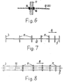
- the number of holding elements 11 depends on the properties of the processed Veins 1 and after the distance between the guide disc 3 and Stranding washer 5. The greater this distance, the more Holding washers 11 are used. Your distance from each other can be constant but also arbitrary. In the preferred embodiment is the distance between the holding elements 11 from each other with increasing distance from the guide disc 3 smaller, as can be seen from FIGS. 7 and 8. In the area of the stranding disk 5 are therefore for guiding Veins 1 more holding elements 11 available than in the area of Guide disc 3. The wires 1 are in the area with the larger angles of rotation led closer.
Landscapes
- Engineering & Computer Science (AREA)
- Manufacturing & Machinery (AREA)
- Ropes Or Cables (AREA)
- Wire Processing (AREA)
- Investigating Strength Of Materials By Application Of Mechanical Stress (AREA)
- Processes Specially Adapted For Manufacturing Cables (AREA)
- Vessels, Lead-In Wires, Accessory Apparatuses For Cathode-Ray Tubes (AREA)
Claims (4)
- Dispositif pour le câblage réversible d'éléments de câble (1) comprenant un disque de guidage (3) fixe et un disque de câblage (5) disposée à distance du disque de guidage et tournant autour de son axe qui présentent tous deux des trous traversants (13) axiaux pour le passage des éléments de câble (1) ainsi qu'un point fixe pour la fixation des éléments de câble (1) câblés, un point de câblage (6) et au moins un élément de support (12, 15) sous forme de fil résistant à la traction qui est disposé entre le disque de guidage ( 3) et le disque de câblage (5) et sur lequel au moins un élément de maintien (11) en forme de disque est monté à distance du disque de guidage (3) d'une part et du disque de câblage (5) d'autre part, lequel élément de maintien est pourvu de trous traversants (13) axiaux pour le passage des éléments de câble (1), l'élément de support (12; 15), à l'état tendu étant disposé entre le disque de guidage (3) et le disque de câblage (5), caractérisé par le fait que l'élément de maintien (11) est monté libre mais fixe dans la direction axiale sur l'élément de support (12, 15).
- Dispositif selon la revendication 1, caractérisé par le fait que deux éléments de support (12, 15) ou plus sont montés entre le disque de guidage (3) et le disque de câblage (5), lesquels éléments de support sont répartis de manière symétrique dans la direction circonférentielle des disques (3, 5) et de l'élément de maintien (11).
- Dispositif selon une des revendications 1 ou 2, caractérisé par le fait que le disque de guidage (3) et le disque de câblage (5) ainsi que tous les éléments de maintien (11) sont pourvus d'un trou traversant (14) central.
- Dispositif selon une des revendications 1 à 3, caractérisé par le fait que, lorsqu'on utilise plus de trois éléments de maintien (11) leur espacement mutuel décroít au fur et à mesure que la distance par rapport au disque de guidage (3) augmente.
Applications Claiming Priority (4)
| Application Number | Priority Date | Filing Date | Title |
|---|---|---|---|
| DE19924226514 DE4226514A1 (de) | 1992-08-11 | 1992-08-11 | Vorrichtung zur reversierenden Verseilung von Verseilelementen |
| DE4226514 | 1992-08-11 | ||
| DE19934317496 DE4317496A1 (de) | 1993-05-26 | 1993-05-26 | Vorrichtung zur reversierenden Verseilung von Verseilelementen |
| DE4317496 | 1993-05-26 |
Publications (2)
| Publication Number | Publication Date |
|---|---|
| EP0582802A1 EP0582802A1 (fr) | 1994-02-16 |
| EP0582802B1 true EP0582802B1 (fr) | 1999-03-10 |
Family
ID=25917409
Family Applications (1)
| Application Number | Title | Priority Date | Filing Date |
|---|---|---|---|
| EP93109183A Expired - Lifetime EP0582802B1 (fr) | 1992-08-11 | 1993-06-08 | Dispositif pour la fabrication de câbles à sens de câblage alterné |
Country Status (6)
| Country | Link |
|---|---|
| EP (1) | EP0582802B1 (fr) |
| AT (1) | ATE177485T1 (fr) |
| CA (1) | CA2103746C (fr) |
| DE (1) | DE59309423D1 (fr) |
| ES (1) | ES2131084T3 (fr) |
| FI (1) | FI100893B (fr) |
Families Citing this family (8)
| Publication number | Priority date | Publication date | Assignee | Title |
|---|---|---|---|---|
| AT401533B (de) * | 1994-06-28 | 1996-09-25 | Bergsmann Ludwig | Vorrichtung zum herstellen einer kabelverseilung mit wechselnder schlagrichtung |
| AT478U1 (de) * | 1994-10-25 | 1995-11-27 | Schwechater Kabelwerke | Einrichtung zum zufuehren von seilelementen zum verseilkopf einer wechselschlagverseilmaschine |
| AT402305B (de) * | 1995-06-06 | 1997-04-25 | Seibert Gerhard Ing | Vorrichtung zur herstellung einer kabelverseilung |
| AT404265B (de) * | 1995-06-12 | 1998-10-27 | Gerhard Ing Seibert | Verfahren zum herstellen einer kabelverseilung |
| FR2737337B1 (fr) * | 1995-07-26 | 1997-09-19 | Kertscher Sa E | Station de cablage pour machine de cablage alterne ou de type sz |
| DK0932165T3 (da) * | 1998-01-23 | 2007-09-10 | Rosendahl Masch Gmbh | Indretning til fremstilling af en kabelslåning |
| AT407266B (de) * | 1999-03-24 | 2001-02-26 | Schwechater Kabelwerke | Einrichtung zum zuführen von seilelementen zum verseilkopf einer wechselschlagverseilmaschine |
| CN110729082B (zh) * | 2019-11-11 | 2025-07-01 | 合肥神马科技集团有限公司 | 一种卧式成缆机绞体 |
Family Cites Families (3)
| Publication number | Priority date | Publication date | Assignee | Title |
|---|---|---|---|---|
| NL6716538A (fr) * | 1967-12-05 | 1969-06-09 | ||
| AU3212571A (en) * | 1970-08-13 | 1973-02-15 | Dunlop Australia Limited | Improvements in reinforced articles |
| CA1113806A (fr) * | 1979-12-19 | 1981-12-08 | Bretislav P. Zuber | Methode de toronnage de fils |
-
1993
- 1993-06-08 DE DE59309423T patent/DE59309423D1/de not_active Expired - Fee Related
- 1993-06-08 ES ES93109183T patent/ES2131084T3/es not_active Expired - Lifetime
- 1993-06-08 AT AT93109183T patent/ATE177485T1/de not_active IP Right Cessation
- 1993-06-08 EP EP93109183A patent/EP0582802B1/fr not_active Expired - Lifetime
- 1993-08-10 CA CA002103746A patent/CA2103746C/fr not_active Expired - Fee Related
- 1993-08-10 FI FI933530A patent/FI100893B/fi not_active IP Right Cessation
Also Published As
| Publication number | Publication date |
|---|---|
| ES2131084T3 (es) | 1999-07-16 |
| FI100893B (fi) | 1998-03-13 |
| EP0582802A1 (fr) | 1994-02-16 |
| FI933530L (fi) | 1994-02-12 |
| FI933530A0 (fi) | 1993-08-10 |
| DE59309423D1 (de) | 1999-04-15 |
| CA2103746A1 (fr) | 1994-02-12 |
| ATE177485T1 (de) | 1999-03-15 |
| CA2103746C (fr) | 1997-10-21 |
Similar Documents
| Publication | Publication Date | Title |
|---|---|---|
| DE3779755T2 (de) | Alternatives umkehrzwirnverfahren und alternative umkehrzwirnvorrichtung. | |
| DE2330409C2 (de) | Doppeldrall-Verseilmaschine | |
| EP0582802B1 (fr) | Dispositif pour la fabrication de câbles à sens de câblage alterné | |
| DE69203179T2 (de) | Reversierende Verseilvorrichtung. | |
| DE2813966C2 (fr) | ||
| DE69604543T2 (de) | Verseilanlage für reversierenden oder SZ Verseilmaschine | |
| DE3023257C2 (fr) | ||
| DE1134130B (de) | Verfahren zur Lagenverseilung von Fernmeldekabel-Verseilelementen | |
| EP0663101B1 (fr) | Procede et dispositif permettant de toronner des elements allonges | |
| DE1105015B (de) | Maschine zum Herstellen von Verseilelementen fuer den Aufbau elektrischer Kabel | |
| DE2615275A1 (de) | Verseilvorrichtung zur herstellung von elektrischen kabeln oder leitungen | |
| DE3109756C2 (de) | Vertikale Verseilmaschine | |
| DE3013933C2 (de) | Vorrichtung zum lagenweisen SZ-Verseilen von Verseilelementen elektrischer Kabel | |
| DE19501001C2 (de) | Vorrichtung zur reversierenden Verseilung von Verseilelementen | |
| DE2412199C2 (de) | Verfahren zur abschnittsweise mit wechselnder Drallrichtung bzw. Drallänge erfolgenden Verseilung von elektrischen Kabeln oder Leitungen | |
| DE4226514A1 (de) | Vorrichtung zur reversierenden Verseilung von Verseilelementen | |
| DE1811176A1 (de) | Kabelwickelmaschine | |
| DE69203180T2 (de) | Reversierende Verseilvorrichtung. | |
| DE2123852C3 (de) | Vorrichtung zum Verseilen von Verseilelementen für Fernmeldekabel | |
| DE1510121C3 (de) | Flügelzwirnmaschine zur Herstellung eines aus Stahldrähten bestehenden Drahtseils kleinen Querschnitts | |
| DE1785448A1 (de) | Mehrfachdrallspindel | |
| EP3775367B1 (fr) | Machine à toronner | |
| DE2213917C3 (de) | Vorrichtung an einer Wickelmaschine zum Verstärken von Wicklungsenden | |
| DE4317496A1 (de) | Vorrichtung zur reversierenden Verseilung von Verseilelementen | |
| DE4001837C2 (fr) |
Legal Events
| Date | Code | Title | Description |
|---|---|---|---|
| PUAI | Public reference made under article 153(3) epc to a published international application that has entered the european phase |
Free format text: ORIGINAL CODE: 0009012 |
|
| 17P | Request for examination filed |
Effective date: 19931206 |
|
| AK | Designated contracting states |
Kind code of ref document: A1 Designated state(s): AT CH DE ES FR GB IT LI SE |
|
| 17Q | First examination report despatched |
Effective date: 19960429 |
|
| RAP1 | Party data changed (applicant data changed or rights of an application transferred) |
Owner name: FRISCH GMBH |
|
| GRAG | Despatch of communication of intention to grant |
Free format text: ORIGINAL CODE: EPIDOS AGRA |
|
| GRAG | Despatch of communication of intention to grant |
Free format text: ORIGINAL CODE: EPIDOS AGRA |
|
| GRAH | Despatch of communication of intention to grant a patent |
Free format text: ORIGINAL CODE: EPIDOS IGRA |
|
| GRAH | Despatch of communication of intention to grant a patent |
Free format text: ORIGINAL CODE: EPIDOS IGRA |
|
| GRAA | (expected) grant |
Free format text: ORIGINAL CODE: 0009210 |
|
| AK | Designated contracting states |
Kind code of ref document: B1 Designated state(s): AT CH DE ES FR GB IT LI SE |
|
| REF | Corresponds to: |
Ref document number: 177485 Country of ref document: AT Date of ref document: 19990315 Kind code of ref document: T |
|
| REG | Reference to a national code |
Ref country code: CH Ref legal event code: EP |
|
| REF | Corresponds to: |
Ref document number: 59309423 Country of ref document: DE Date of ref document: 19990415 |
|
| ET | Fr: translation filed | ||
| REG | Reference to a national code |
Ref country code: CH Ref legal event code: NV Representative=s name: RIEDERER HASLER & PARTNER PATENTANWAELTE AG |
|
| REG | Reference to a national code |
Ref country code: ES Ref legal event code: FG2A Ref document number: 2131084 Country of ref document: ES Kind code of ref document: T3 |
|
| GBV | Gb: ep patent (uk) treated as always having been void in accordance with gb section 77(7)/1977 [no translation filed] |
Effective date: 19990310 |
|
| REG | Reference to a national code |
Ref country code: GB Ref legal event code: 710B Free format text: REQUEST HAS BEEN FILED UNDER RULE 110(4) OF THE RULES 1995 TO EXTEND THE PERIOD FOR FILING A TRANSLATION OF THE SPECIFICATION. THIS PATENT WAS ANNOUNCED AS VOID IN THE PATENT AND DESIGNS JOURNAL 5757 DATED 08.09.1999. |
|
| GBT | Gb: translation of ep patent filed (gb section 77(6)(a)/1977) |
Effective date: 19991122 |
|
| REG | Reference to a national code |
Ref country code: GB Ref legal event code: 710B Free format text: FOLLOWING A REQUEST UNDER RULE 110(4) OF THE RULES 1995 TO EXTEND THE PERIOD FOR FILING A TRANSLATION OF THE SPECIFICATION, A TRANSLATION HAS NOW BEEN FILED IN ACCORDANCE WITH SECTION 77(6)(A). |
|
| PLBE | No opposition filed within time limit |
Free format text: ORIGINAL CODE: 0009261 |
|
| STAA | Information on the status of an ep patent application or granted ep patent |
Free format text: STATUS: NO OPPOSITION FILED WITHIN TIME LIMIT |
|
| 26N | No opposition filed | ||
| REG | Reference to a national code |
Ref country code: GB Ref legal event code: IF02 |
|
| PGFP | Annual fee paid to national office [announced via postgrant information from national office to epo] |
Ref country code: GB Payment date: 20030604 Year of fee payment: 11 |
|
| PGFP | Annual fee paid to national office [announced via postgrant information from national office to epo] |
Ref country code: FR Payment date: 20030605 Year of fee payment: 11 |
|
| PGFP | Annual fee paid to national office [announced via postgrant information from national office to epo] |
Ref country code: ES Payment date: 20030606 Year of fee payment: 11 |
|
| PGFP | Annual fee paid to national office [announced via postgrant information from national office to epo] |
Ref country code: DE Payment date: 20030611 Year of fee payment: 11 |
|
| PGFP | Annual fee paid to national office [announced via postgrant information from national office to epo] |
Ref country code: AT Payment date: 20030618 Year of fee payment: 11 |
|
| PGFP | Annual fee paid to national office [announced via postgrant information from national office to epo] |
Ref country code: SE Payment date: 20030626 Year of fee payment: 11 |
|
| PGFP | Annual fee paid to national office [announced via postgrant information from national office to epo] |
Ref country code: CH Payment date: 20030702 Year of fee payment: 11 |
|
| PG25 | Lapsed in a contracting state [announced via postgrant information from national office to epo] |
Ref country code: GB Free format text: LAPSE BECAUSE OF NON-PAYMENT OF DUE FEES Effective date: 20040608 Ref country code: AT Free format text: LAPSE BECAUSE OF NON-PAYMENT OF DUE FEES Effective date: 20040608 |
|
| PG25 | Lapsed in a contracting state [announced via postgrant information from national office to epo] |
Ref country code: SE Free format text: LAPSE BECAUSE OF NON-PAYMENT OF DUE FEES Effective date: 20040609 Ref country code: ES Free format text: LAPSE BECAUSE OF NON-PAYMENT OF DUE FEES Effective date: 20040609 |
|
| PG25 | Lapsed in a contracting state [announced via postgrant information from national office to epo] |
Ref country code: LI Free format text: LAPSE BECAUSE OF NON-PAYMENT OF DUE FEES Effective date: 20040630 Ref country code: CH Free format text: LAPSE BECAUSE OF NON-PAYMENT OF DUE FEES Effective date: 20040630 |
|
| PG25 | Lapsed in a contracting state [announced via postgrant information from national office to epo] |
Ref country code: DE Free format text: LAPSE BECAUSE OF NON-PAYMENT OF DUE FEES Effective date: 20050101 |
|
| GBPC | Gb: european patent ceased through non-payment of renewal fee |
Effective date: 20040608 |
|
| EUG | Se: european patent has lapsed | ||
| EUG | Se: european patent has lapsed | ||
| REG | Reference to a national code |
Ref country code: CH Ref legal event code: PL |
|
| PG25 | Lapsed in a contracting state [announced via postgrant information from national office to epo] |
Ref country code: FR Free format text: LAPSE BECAUSE OF NON-PAYMENT OF DUE FEES Effective date: 20050228 |
|
| REG | Reference to a national code |
Ref country code: FR Ref legal event code: ST |
|
| PG25 | Lapsed in a contracting state [announced via postgrant information from national office to epo] |
Ref country code: IT Free format text: LAPSE BECAUSE OF NON-PAYMENT OF DUE FEES Effective date: 20050608 |
|
| REG | Reference to a national code |
Ref country code: ES Ref legal event code: FD2A Effective date: 20040609 |