EP0582832A2 - Elément réflécteur et arrangement de ces éléments pour l'éclairage indirect de locaux de bâtiments - Google Patents
Elément réflécteur et arrangement de ces éléments pour l'éclairage indirect de locaux de bâtiments Download PDFInfo
- Publication number
- EP0582832A2 EP0582832A2 EP93110810A EP93110810A EP0582832A2 EP 0582832 A2 EP0582832 A2 EP 0582832A2 EP 93110810 A EP93110810 A EP 93110810A EP 93110810 A EP93110810 A EP 93110810A EP 0582832 A2 EP0582832 A2 EP 0582832A2
- Authority
- EP
- European Patent Office
- Prior art keywords
- reflector
- secondary reflector
- partial
- arrangement
- light
- Prior art date
- Legal status (The legal status is an assumption and is not a legal conclusion. Google has not performed a legal analysis and makes no representation as to the accuracy of the status listed.)
- Granted
Links
- 230000003595 spectral effect Effects 0.000 claims description 9
- 230000005855 radiation Effects 0.000 claims description 5
- 239000003365 glass fiber Substances 0.000 claims description 3
- 239000012141 concentrate Substances 0.000 claims description 2
- 238000009826 distribution Methods 0.000 description 15
- 238000005286 illumination Methods 0.000 description 8
- 230000000007 visual effect Effects 0.000 description 8
- 238000009434 installation Methods 0.000 description 6
- 239000011248 coating agent Substances 0.000 description 5
- 238000000576 coating method Methods 0.000 description 5
- 238000012423 maintenance Methods 0.000 description 5
- 238000004519 manufacturing process Methods 0.000 description 4
- 230000008901 benefit Effects 0.000 description 3
- 238000007493 shaping process Methods 0.000 description 3
- 230000008859 change Effects 0.000 description 2
- 230000001427 coherent effect Effects 0.000 description 2
- 238000010276 construction Methods 0.000 description 2
- 230000004313 glare Effects 0.000 description 2
- 239000000463 material Substances 0.000 description 2
- 238000000034 method Methods 0.000 description 2
- 239000000203 mixture Substances 0.000 description 2
- 230000003287 optical effect Effects 0.000 description 2
- 230000008447 perception Effects 0.000 description 2
- 239000011505 plaster Substances 0.000 description 2
- 239000000843 powder Substances 0.000 description 2
- 241000446313 Lamella Species 0.000 description 1
- 238000004378 air conditioning Methods 0.000 description 1
- 230000015572 biosynthetic process Effects 0.000 description 1
- 230000001419 dependent effect Effects 0.000 description 1
- 230000000694 effects Effects 0.000 description 1
- 230000006870 function Effects 0.000 description 1
- 229910052736 halogen Inorganic materials 0.000 description 1
- 150000002367 halogens Chemical class 0.000 description 1
- 238000003384 imaging method Methods 0.000 description 1
- 230000035764 nutrition Effects 0.000 description 1
- 235000016709 nutrition Nutrition 0.000 description 1
- 238000010422 painting Methods 0.000 description 1
- 238000005192 partition Methods 0.000 description 1
- 230000008569 process Effects 0.000 description 1
- 230000009467 reduction Effects 0.000 description 1
- 238000002310 reflectometry Methods 0.000 description 1
- 230000000630 rising effect Effects 0.000 description 1
- 238000007788 roughening Methods 0.000 description 1
- 238000004088 simulation Methods 0.000 description 1
- 238000003860 storage Methods 0.000 description 1
- 238000004381 surface treatment Methods 0.000 description 1
Images

Classifications
-
- E—FIXED CONSTRUCTIONS
- E04—BUILDING
- E04B—GENERAL BUILDING CONSTRUCTIONS; WALLS, e.g. PARTITIONS; ROOFS; FLOORS; CEILINGS; INSULATION OR OTHER PROTECTION OF BUILDINGS
- E04B9/00—Ceilings; Construction of ceilings, e.g. false ceilings; Ceiling construction with regard to insulation
- E04B9/32—Translucent ceilings, i.e. permitting both the transmission and diffusion of light
-
- E—FIXED CONSTRUCTIONS
- E04—BUILDING
- E04B—GENERAL BUILDING CONSTRUCTIONS; WALLS, e.g. PARTITIONS; ROOFS; FLOORS; CEILINGS; INSULATION OR OTHER PROTECTION OF BUILDINGS
- E04B9/00—Ceilings; Construction of ceilings, e.g. false ceilings; Ceiling construction with regard to insulation
- E04B9/04—Ceilings; Construction of ceilings, e.g. false ceilings; Ceiling construction with regard to insulation comprising slabs, panels, sheets or the like
-
- F—MECHANICAL ENGINEERING; LIGHTING; HEATING; WEAPONS; BLASTING
- F21—LIGHTING
- F21S—NON-PORTABLE LIGHTING DEVICES; SYSTEMS THEREOF; VEHICLE LIGHTING DEVICES SPECIALLY ADAPTED FOR VEHICLE EXTERIORS
- F21S11/00—Non-electric lighting devices or systems using daylight
-
- F—MECHANICAL ENGINEERING; LIGHTING; HEATING; WEAPONS; BLASTING
- F21—LIGHTING
- F21V—FUNCTIONAL FEATURES OR DETAILS OF LIGHTING DEVICES OR SYSTEMS THEREOF; STRUCTURAL COMBINATIONS OF LIGHTING DEVICES WITH OTHER ARTICLES, NOT OTHERWISE PROVIDED FOR
- F21V7/00—Reflectors for light sources
- F21V7/04—Optical design
-
- F—MECHANICAL ENGINEERING; LIGHTING; HEATING; WEAPONS; BLASTING
- F21—LIGHTING
- F21V—FUNCTIONAL FEATURES OR DETAILS OF LIGHTING DEVICES OR SYSTEMS THEREOF; STRUCTURAL COMBINATIONS OF LIGHTING DEVICES WITH OTHER ARTICLES, NOT OTHERWISE PROVIDED FOR
- F21V7/00—Reflectors for light sources
- F21V7/04—Optical design
- F21V7/05—Optical design plane
Definitions
- the invention relates to a secondary reflector element, a secondary reflector arrangement with a plurality of such secondary reflector elements and a room lighting arrangement with a light source and such a secondary reflector element or such a secondary reflector arrangement.
- a room can only be illuminated with daylight if the outside brightness is sufficient. If this is not the case, for example at dusk, at night or in bad weather, the room must also be illuminated with artificial light.
- DE 35 23 523 C2 describes a device for illuminating an interior with natural daylight, in which a number of reflectors with mutually facing reflection surfaces are arranged alternately below the ceiling so that incident light from the window side via the individual reflectors also into areas of the room that are relatively far away from the window.
- a certain distance is required between the reflectors, which in turn makes it necessary to increase the room height accordingly.
- CH 675 015 A5 discloses a method for light distribution in a closed room, in which light incident from the window side into the room is to be distributed by specially designed reflectors on the wall in the room.
- the object of the invention is to provide an improved lighting option.
- a secondary reflector element is proposed with a visible support surface and a plurality of partial reflector surfaces which are very small in relation to the size of the support surface, each of which has a predetermined shape and orientation with respect to the support surface, the support surface on the one hand and the partial reflector surfaces on the other hand having different reflection behavior.
- a secondary reflector element of this type can cause the reflected light to have both a direct and an indirect part.
- the direct component can then be used to provide the necessary brightness, while the indirect component generates a diffuse light.
- the luminance, ie the perceived brightness on the reflector element can be kept relatively low, so that there is no glare.
- a mixture of diffuse and direct light can be achieved with such a secondary reflector element in a very simple manner, so that shadows are created on the one hand, which support the visual spatial perception, on the other hand however, these shadows also do not become unnaturally hard, which in turn affects the visual spatial perception.
- the proportion of diffuse and direct light can be adjusted by the choice of the dimensions of the partial reflector surfaces in relation to the carrier surface or the ratio of the total surface of the partial reflector surfaces to the carrier surface. Since the partial reflector surfaces are very small in relation to the size of the support surface, the reflection does not produce large, coherent, brightly illuminated surfaces that can be perceived as unpleasant by an observer. Rather, the viewer sees in the illuminated secondary reflector element a surface that is bright but pleasantly perceived due to the different reflection behavior, which, with a corresponding selection of the illuminance of the lighting, provides glare-free or low-glare, but nevertheless bright illumination.
- DE 37 43 133 A1 describes a device for indirect lighting of interiors in which a commercially available broadband daylight emitter is used together with a special plaster surface of uniformly high reflectivity. With such a plaster surface, however, targeted control of the light distribution is practically impossible or can only be achieved with extremely great difficulty.
- CH 675 015 A5 also describes structured surfaces that are sawtooth-shaped or ribbed or have concave or convex cutouts.
- the use of parallel lamellas is also proposed, the inclination of which should ensure a certain light guide.
- These surface structures or lamellae are also flat, which means that they only require a low overall height.
- the optical However, options are limited. To the viewer, they look like a single coherent surface with the corresponding glare effect. In addition, such structured surfaces look very uneasy when not illuminated. Architecturally, they can only be used to a limited extent.
- the support surface remains visible.
- the partial reflector surfaces interrupt the visual impression of the support surface, but this does not contribute significantly to any concern.
- the visual impression is particularly significantly improved in that the partial reflector surfaces are very small in relation to the size of the support surface.
- this also has the technical advantage that the overall height of the secondary reflector element can be kept very small.
- the partial reflector surfaces are aligned essentially parallel to an imaginary reflector shape and shifted relative to the imaginary reflector shape while maintaining their alignment in space so that they are held in the area of the support surface common to all partial reflector surfaces.
- the partial reflector surfaces can be attached to the support surface. If this should be necessary for design reasons, they can also be at a small distance from the support surface.
- a predetermined reflection behavior can now be achieved, namely a desired light conduction or distribution according to the imaginary reflector, without an appreciable overall height being required.
- the reflection behavior can be very well simulated to that of a real spatially designed secondary reflector, one can become familiar with such a secondary reflector element limit practically to a flat design, ie the secondary reflector element no longer requires any significant height.
- the partial reflector surfaces advantageously project in relation to the support surface. This largely prevents shading of the partial reflector surfaces by a body having the support surface.
- the direction from which light should strike the element can be chosen with a higher degree of freedom.
- the support surface has a more diffuse reflection behavior than the partial reflector surfaces.
- the carrier surface is therefore responsible for the indirect part of the reflected light, while the partial reflector surfaces are responsible for the direct part. This has the advantage that, with the aid of the partial reflector surfaces, the direct portion of the reflected light can be directed at areas in which a higher brightness is desired. By creating such light zones, the visual impression of a room can be improved considerably. In addition, the average illuminance can be reduced cost-effectively in this way outside the area of the actual visual task.
- the carrier surface is preferably surface-treated, in particular to avoid reflection.
- it can be blackened, matted, roughened, lacquered or powder-coated, for example, or provided with a non-reflective coating.
- the direct reflection behavior of the element is determined exclusively by the partial reflector surfaces.
- the element can be used as an architectural design element, the visual impression of which is essentially due to the Surface treatment of the support surface is determined.
- the secondary reflector element can thus practically take on the color or surface design of a conventional ceiling and still be used for targeted illumination of the room.
- the carrier surface advantageously has a reflection behavior which causes a spectral shift of the incident light to the emerging light.
- a light milieu control can then be achieved with such a reflector element.
- the shift in the spectral distribution can be brought about, for example, in that the carrier surface reflects individual spectral components of the incident light more than others. For example, a stronger reflection of the red components of the incident light can produce a warmer tone in the room.
- the direct portion reflected by the partial reflector surfaces can remain unaffected. So you can use a single secondary reflector to bring the light required to generate the necessary brightness to the desired location and to generate the desired spectral distribution of the light.
- the reflected light is composed of the superposition of the direct part and the indirect part. The overall distribution and thus also the spectral distribution can be controlled to a greater extent than previously with such a reflector element.
- the carrier surface and optionally the partial reflector surfaces preferably absorb UV radiation at least partially.
- the secondary reflector element can then be irradiated with so-called hot illuminants, such as halogen or high-pressure steam lamps, for which a filter disk is normally necessary in the beam path.
- hot illuminants such as halogen or high-pressure steam lamps, for which a filter disk is normally necessary in the beam path.
- this filter disc can be replaced by the appropriate coating.
- the carrier surface in space advantageously forms a straight or curved line in section.
- the support surface is therefore at least two-dimensional in space. With a two-dimensional design, the support surface forms a plane in space. However, it can also be designed as a three-dimensional surface. In this case, for example, it can form a curved surface in space. However, the orientation or alignment of the partial reflector surfaces in space is still based exclusively on the imaginary reflector shape. It is independent of the shape of the support surface in the room.
- the support surface has a spatial shape that is adapted to the spatial shape of a base. This may be necessary if the element is to be attached to surfaces that are not level, for example when a ceiling changes into a sloping roof or when a ceiling changes into the underside of a staircase. In these cases too, the element can be used for lighting with full design options.
- the projection of the partial reflector surfaces onto the imaginary reflector shape preferably covers only a part of this reflector shape.
- the imaginary reflector shape is, so to speak, perforated. This is another design element.
- the intensity of the light that would be reflected by the imaginary reflector shape can also be weakened with this configuration in the secondary reflector element or distributed differently, for example diffusely, so that design options for further reflection focal points or other light distribution options remain.
- the partial reflector surfaces are advantageously arranged in rows at a distance from one another. This facilitates the design and manufacture of an element.
- the rows do not have to be straight, they can also be curved, e.g. lying on circular lines.
- the imaginary reflector shape could have the shape of a hemisphere or a truncated cone, for example.
- the spacing of the rows from one another is smaller than the depth of a shadow region produced by shading in the beam direction and the partial reflector surfaces are arranged in a gap with one another.
- the spacing of the rows can be reduced by the arrangement on a gap with one another and thus the density of the partial reflector surfaces can be increased.
- the total area of the partial reflector surfaces that is to say the sum of the individual surfaces of each partial reflector, is not increased or not significantly increased with this configuration, this configuration achieves a reflection behavior which is perceived as very pleasant for a viewer.
- the support surface is preferably a surface of a flat support from which the partial reflector surfaces are formed.
- the flat beam does not require any significant height.
- the partial reflector surfaces can be produced with the desired shape by the shaping.
- the extension of the partial reflector surfaces perpendicular to the carrier surface should be less than ten times the thickness of the carrier. Even after the partial reflector surfaces have been formed from the carrier, the element is still flat. If, for example, the carrier is formed from a 1 mm thick sheet, the finished one Element with the shaped partial reflector surfaces the thickness of a few millimeters, for example 5 mm.
- the partial reflector surfaces they can be deep-drawn, punched, cast or embossed from the carrier. With such manufacturing processes, large quantities can be manufactured with reasonable effort.
- the carrier after the shaping of the partial reflector surfaces, has openings in the region of the partial reflector surfaces.
- the imaginary reflector is essentially flat.
- all partial reflector surfaces can be parallel to each other, which considerably simplifies production.
- the invention also relates to a secondary reflector arrangement with a plurality of secondary reflector elements, in which the angle of reflection of the imaginary reflectors for each secondary reflector element becomes smaller with increasing distance from a light source.
- the reflection angle is the difference between the angle of incidence and the angle of reflection of the reflected light.
- a first group of secondary reflector elements is provided, the reflection angle of the imaginary reflector becomes smaller with increasing distance from the light source, and a second group of secondary reflector elements whose partial reflector surfaces concentrate incident light on a predetermined target area.
- the secondary reflector elements of the first and the second group can preferably be arranged mixed with one another. This makes the design easier.
- the invention also relates to a room lighting arrangement with a light source and a secondary reflector element or a secondary reflector arrangement, in which the secondary reflector element or the secondary reflector arrangement is arranged on a wall of the room and the light source generates a directed light at a predetermined angle to this wall.
- the angle can be relatively flat. It is only limited by the shading of the individual partial reflector surfaces.
- the wall of the room is the ceiling.
- the room lighting arrangement presented can now achieve that practically no additional room height is required.
- a safety distance, which must be maintained by a lamp downwards, can be almost completely eliminated.
- the ceiling can therefore be arranged lower than before. In the case of a ten-story building, height can certainly be gained for an additional floor. Since the light source can be set up independently of the secondary reflector arrangement, you can Installation location, for example, be chosen so that it is easily accessible for maintenance work. No more ladders or lifting platforms are required to replace lamps.
- the light source is preferably one or more high-intensity emitters. These emitters are then directed onto the secondary reflector elements which, depending on the design of the imaginary reflector, distribute the reflected light evenly in the room or direct it onto a desired surface area.
- a daylight deflection device arranged in particular in the area of a window can also be used as the light source. If necessary, this can be used together with the spotlight, so that daylight illumination is obtained during the day, but artificial light illumination is obtained at dusk and in the evening, the same secondary reflector elements being used for both types of illumination.
- the daylight deflection device has a prism arrangement or a light guide arrangement, in particular formed with glass fibers, which in particular essentially guides only zenith light into the room.
- Zenith light is to be understood as light which is free from direct sun rays and which is essentially formed by sunlight scattered in the atmosphere. In relation to the very bright sunlight, zenith light is not perceived as disturbing by the room users.
- the light source is preferably arranged on a wall enclosing an angle, in particular 90 °, with the wall supporting the secondary reflector or the secondary reflector arrangement.
- the installation and maintenance are very simple and therefore cheaper. All electrical connections can then be made in this wall. Cabling to the ceiling is not necessary.
- electrical lines are already running on the wall, so that electrical energy for the light source can easily be extracted here.
- the electrical lines can be concentrated overall, which saves material and labor, the latter both during installation and later during maintenance.
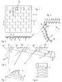
- a secondary reflector element 1 has a carrier surface 2, in which a multiplicity of partial reflector surfaces 3 are arranged.
- the carrier surface 2 is here the surface of a flat carrier 4, for example a sheet from which the partial reflector surfaces are formed, for example by stamping. Through the formation of the partial reflector surfaces 3 from the carrier 4 openings 5 have been created.
- the imaginary reflector is divided into a plurality of partial areas 7-13, which are framed in FIG. 3. These partial areas do not have to cover the entire imaginary reflector 6. In reality, however, they are closer together, so they do not leave the large gaps shown open.
- the illustration has been simplified for the sake of clarity. Now choose the support surface 2 'in the room. In the present case, it is designed as a flat surface. The individual partial surfaces 7-13 of the imaginary reflector 6 are now shifted in space while maintaining their alignment, until they are held with an edge on the support surface 2 '.
- the partial surface 7 has been displaced along the arrow 14 substantially perpendicular to its main reflection surface, that is to say in the direction of its surface normal or parallel to its main reflection direction.
- the shift in the main reflection direction is preferred because it simulates the imaging behavior of the imaginary reflector 6 relatively precisely.
- the partial surface 7 is therefore on the support surface 2 'has become its partial reflector surface 7' while maintaining its orientation in space.
- the partial reflector surface 8 is also shifted to the support surface 2 'while maintaining its orientation in space in the direction of arrow 42 such that it appears there as a partial reflector surface 8'.
- the shift is not perpendicular to its main reflection surface, that is, it is not parallel to its main reflection direction.
- the partial surfaces 9-13 become partial reflection surfaces 9 ', 10', 11 ', 12', 13 '.
- the secondary reflector element 1 'thus finished now has essentially the same reflection behavior as the imaginary reflector 6. However, it requires a significantly lower overall height than the reflector 6. The overall height is essentially only dependent on the type of material used.
- the partial areas 7-13 are shown relatively large. They can also be made smaller, which also results in a reduction in the overall height.
- the reflection behavior of the secondary reflector element 1 ' is not identical to that of the imaginary reflector 6.
- the reflection behavior is also determined, among other things, by the distance of the reflector surfaces from the light source, which has changed during the shaping of the imaginary reflector 6 to the secondary reflector element 1'.
- this does not play a major role, since if possible, spot lighting is not used for room lighting, but rather area lighting that can be viewed with good nutrition as being generated by an infinitely distant light source. For such light, however, there is practically no difference in the reflection behavior between the imaginary reflector 6 and the secondary reflector element 1 '.
- the partial reflector surfaces 3 are arranged in a row in several rows, the partial reflector surfaces of two successive rows being set to one another, i.e. a partial reflector surface 3 'is located behind a gap 14 between the partial reflector surfaces 3' 'of an adjacent row of partial reflector surfaces.
- the total area of the partial reflector areas i.e. the sum of all partial reflector areas 3 is not increased by this.
- the visual impression that a viewer of the illuminated or irradiated secondary reflector element 1 receives is nevertheless more pleasant. He not only sees a few solidly radiating light spots, but a large number of small light spots, namely the image of the light source in each of the partial reflector surfaces 3.
- the carrier surface 2 reflects more diffusely than the partial reflector surfaces 3.
- it can be surface-treated, for example by matting, painting, blackening, roughening, powder coating or provided with a coating that does not reflect, in order to increase the design options with the secondary reflector element 1.
- the support surface 2 has the same color as a wall or ceiling 16 (FIG. 7) to which the secondary reflector element 1 is attached, the secondary reflector element 1 blends in harmoniously with the surroundings without being disruptive. In practice, only the partial reflector surfaces are then for the viewer 3 recognizable.
- the carrier surface 2 and partial reflector surfaces 3 can also have a coating that absorbs UV radiation. Even if the incident light contains UV radiation, this UV radiation is not reflected back into the room.
- the carrier surface 2 can have a reflection behavior which leads to a spectral shift of the incident light. This can be achieved, for example, by reflecting certain spectral components of the incident light more than others. For example, if a warmer atmosphere is desired, one will ensure that the red components are reflected more. If a colder atmosphere is desired, the blue components would be reflected more accordingly.
- the support surface 2, ie the support 4, does not have to be flat, as shown in FIGS. 1 to 3. It can also take on any shape in space, as is exemplified by the secondary reflector element 1 ′′ in FIG. 5.
- a secondary reflector element 1 ′′ can be used, for example, if the ceiling to which it is attached is not flat but has steps. This can be the case, for example, if the ceiling of a loft merges into a dormer or if the ceiling continues in the underside of a staircase.
- the secondary reflector element 1 ′′ can also be used in this case.
- the orientation of the partial reflector surfaces 3 is still based on the simulation of the imaginary reflector 6. It is therefore independent of the angle which the partial reflector surfaces 3 make in relation to the support body 4 in the case of a flat secondary reflector element.
- the secondary reflector element 1 ′′ can, for example, be irradiated by a radiator 17 which generates a directed light at a predetermined angle to the ceiling.
- the spotlight can have a high intensity. The only condition for the location of its installation is that it substantially completely illuminates all partial reflector surfaces 3, i.e. no partial reflector surface 3 is shadowed by another.
- the rows of the individual partial reflector surfaces 3 also do not have to be arranged along straight lines. As shown by way of example in FIG. 6, they can also be arranged on circular line sections or other curved lines. This is particularly advantageous if imaginary reflectors with a curvature are to be simulated, for example reflectors which have the shape of a spherical section or a truncated cone or parts thereof. Such reflectors can be used for accent lighting, as will be explained in more detail in connection with FIG. 7.
- the secondary reflector element 1 In the secondary reflector element 1, all the partial reflector surfaces 3 are formed parallel to one another, ie they have the same orientation in space. The corresponding imaginary reflector, not shown, would therefore be essentially flat. Such secondary reflector elements can be manufactured relatively easily and in large numbers. In order to be able to ensure a desired light distribution in the room with these secondary reflector elements, a plurality of secondary reflector elements are combined in a secondary reflector arrangement 20, as is shown schematically in FIG. 4.
- the secondary reflector arrangement 20 has three secondary reflector elements 21, 22, 23, the partial reflector surfaces 24-26 of which have the same orientation in space within a secondary reflector element 21-23 have whose orientation in space changes from secondary reflector element to secondary reflector element.
- This change depends on the distance of the respective secondary reflector element 21-23 from a light source 27.
- the greater the distance the smaller the reflection angle a1, a2, a3.
- the angle of reflection is the difference between the angle of incidence and the angle of reflection. It results from the reflection of the light beams, schematically designated s1, s2, s3, at the partial reflector surfaces 24-26.
- the individual secondary reflector elements 21-23 are selected such that the light beams emitted by the light source 27 are essentially reflected in an area which is located away from the light source. This area would normally have the least light due to its greater distance from the light source, i.e. Light with the lowest intensity, get.
- the choice of the individual secondary reflector elements 21-23 ensures that more light is reflected into this area, so that the disadvantage of the greater distance is compensated for. It is therefore possible to achieve a substantially uniform light distribution in the entire space to be illuminated with the secondary reflector arrangement 20 without having to sacrifice a greater overall height on the ceiling.
- the light source 27 is, for example, a window with a corresponding light deflection device, it is possible in this way to also transport daylight relatively far into a room.
- FIG. 7 shows a room lighting arrangement for a room 28 in which there is a table 29 which is to be illuminated somewhat more strongly. In addition, the room should be illuminated as evenly as possible.
- the room has a window front which is formed from a viewing window 31 and a skylight 32.
- Daylight can enter the room 28 unhindered through the viewing window 31.
- a light deflection arrangement 33 is fastened on a bracket 34, which directs the zenith light 35 into the room 28 and in the process directs it against the ceiling 16 at a small angle.
- five secondary reflector elements are fastened under the ceiling, the secondary reflector elements 21, 22, 23 belonging to a first group of secondary reflector elements whose angle of reflection, as shown in FIG. 4, becomes smaller and smaller as the distance from the light source 32 increases.
- These three secondary reflector elements 21-23 serve to illuminate the room 28 as evenly as possible. It can be seen that the reflected light is stronger in the rear, i.e. part of the room facing away from the window 31 is reflected. The front part, which is closer to the window 31, is still sufficiently illuminated by the light incident through the window.
- 16 secondary reflector elements 36, 37 are arranged under the ceiling, in which the reflection angle is not necessarily selected as a function of the distance of the light source 33. Rather, the angle of reflection is chosen so that the reflected light is directed onto the table 29. In this way, it is possible, for example, to illuminate a workplace better than the rest of the room 28.
- the secondary reflector elements 36, 37 can have a shape as shown in FIG. 6.
- an emitter 38 is arranged on the wall 30. This radiates against the ceiling with a high intensity, as indicated by the arrows 39.
- the light generated by the radiator 38 also strikes the secondary reflector elements 21-23 or 36, 37 and illuminates the room 28 with the same characteristics.
- the radiator 38 can be supplied with electrical voltage by electrical lines 40, which are laid in a cable duct 41 provided in the wall 30. No electrical connections have to be provided in the ceiling 16. This makes installation and maintenance easier. Maintenance of the radiator 38 is also greatly simplified. It can be carried out without the aid of ladders, lifting platforms or scaffolding. A person of normal size who can reach over the viewing window 31 with his hands can change the illuminant of the spotlight 38.
- radiator 38 not only one radiator 38 but a plurality of radiators can be provided, which either emit all in the same direction or can be directed at different secondary reflector elements 21-23 or 36, 37. If necessary, the emitters 38 can also be used together with the daylight 35 if this should be necessary due to insufficient daylight, as occurs, for example, in bad weather or at twilight times.
- the light deflection arrangement 33 can be formed, for example, by a prism arrangement. However, it can also be formed by a light guide arrangement which guides the light into the room, for example with the aid of glass fibers.
- the individual secondary reflector elements can cause different spectral shifts. For example, it may be desirable for the secondary reflector elements 21 and 36 with their support surfaces to reflect the red components of the incident light more strongly, while the other secondary reflector elements 22, 23, 37 reflect the blue components more strongly. This creates a warmer atmosphere in the vicinity of the table 29, so that the table 29 will automatically become a preferred place for people to stay in the room.
Landscapes
- Engineering & Computer Science (AREA)
- Architecture (AREA)
- General Engineering & Computer Science (AREA)
- Physics & Mathematics (AREA)
- Electromagnetism (AREA)
- Civil Engineering (AREA)
- Structural Engineering (AREA)
- Life Sciences & Earth Sciences (AREA)
- Sustainable Development (AREA)
- Non-Portable Lighting Devices Or Systems Thereof (AREA)
- Aerials With Secondary Devices (AREA)
- Optical Elements Other Than Lenses (AREA)
Applications Claiming Priority (2)
| Application Number | Priority Date | Filing Date | Title |
|---|---|---|---|
| DE4222705A DE4222705C2 (de) | 1992-07-10 | 1992-07-10 | Reflektorelement, Reflektorelementanordnung und Raumbeleuchtungsanordnung |
| DE4222705 | 1992-07-10 |
Publications (3)
| Publication Number | Publication Date |
|---|---|
| EP0582832A2 true EP0582832A2 (fr) | 1994-02-16 |
| EP0582832A3 EP0582832A3 (en) | 1994-05-18 |
| EP0582832B1 EP0582832B1 (fr) | 1997-12-10 |
Family
ID=6462927
Family Applications (1)
| Application Number | Title | Priority Date | Filing Date |
|---|---|---|---|
| EP93110810A Expired - Lifetime EP0582832B1 (fr) | 1992-07-10 | 1993-07-07 | Elément réflécteur et arrangement de ces éléments pour l'éclairage indirect de locaux de bâtiments |
Country Status (4)
| Country | Link |
|---|---|
| EP (1) | EP0582832B1 (fr) |
| AT (1) | ATE161084T1 (fr) |
| DE (2) | DE4222705C2 (fr) |
| DK (1) | DK0582832T3 (fr) |
Cited By (4)
| Publication number | Priority date | Publication date | Assignee | Title |
|---|---|---|---|---|
| EP0767341A1 (fr) | 1995-09-07 | 1997-04-09 | Siemens Aktiengesellschaft | Système d'éclairage de locaux utilisant la lumière diurne et artificielle |
| EP0833101A1 (fr) * | 1996-09-26 | 1998-04-01 | VH Lichttechnische Spezialgeräte GmbH | Ensemble réflecteur |
| EP1205744A1 (fr) * | 2000-11-10 | 2002-05-15 | VH Lichttechnische Spezialgeräte GmbH | Appareil pour l'inspection des matériaux avec lumière réflechie approprié pour des caméras |
| US7423054B2 (en) | 2004-11-29 | 2008-09-09 | Warner Lambert Company Llc | Therapeutic pyrazolo[3,4-b]pyridines and indazoles |
Families Citing this family (4)
| Publication number | Priority date | Publication date | Assignee | Title |
|---|---|---|---|---|
| DE4403276C2 (de) * | 1994-01-31 | 1996-07-11 | Jakobiak Roman A Dipl Ing Arch | Tageslichtleitsystem zur verbesserten Tageslichtbeleuchtung von an Gebäudefassaden angrenzenden Innenräumen |
| DE10122878B4 (de) * | 2001-05-11 | 2015-03-26 | BSH Bosch und Siemens Hausgeräte GmbH | Beleuchtungseinrichtung für Backöfen |
| DE10318861B4 (de) * | 2003-04-25 | 2018-06-21 | BSH Bosch und Siemens Hausgeräte GmbH | Gargerät mit einer einen Reflektor aufweisenden Beleuchtungseinrichtung zum Beleuchten eines Garraums |
| DE10318860A1 (de) * | 2003-04-25 | 2004-11-11 | BSH Bosch und Siemens Hausgeräte GmbH | Gargerät |
Family Cites Families (7)
| Publication number | Priority date | Publication date | Assignee | Title |
|---|---|---|---|---|
| US2125319A (en) * | 1934-08-14 | 1938-08-02 | Schlumbohm Peter | Method of illuminating rooms |
| AT265600B (de) * | 1965-12-07 | 1968-10-10 | Andreas Dipl Ing Rippel | Einrichtung zur Verteilung des durch Fenster od. dgl. einfallenden Lichtes in Räumen |
| DE3063584D1 (en) * | 1979-06-05 | 1983-07-07 | Relium Ag | Method and means for controlling the radiation energy of the total spectrum in rooms |
| DE3027400A1 (de) * | 1980-07-19 | 1982-02-18 | Herman Miller Inc., Zeeland, Mich. | Opto-akustisches paneel |
| DE3523523A1 (de) * | 1985-04-29 | 1986-10-30 | Josef Gartner & Co, 8883 Gundelfingen | Vorrichtung zur beleuchtung von innenraeumen mit natuerlichem tageslicht |
| CH675015A5 (fr) * | 1986-09-15 | 1990-08-15 | Peter A Balla | |
| DE9112758U1 (de) * | 1991-10-14 | 1991-11-28 | Brillantleuchten AG, 27442 Gnarrenburg | Halogenleuchte |
-
1992
- 1992-07-10 DE DE4222705A patent/DE4222705C2/de not_active Expired - Fee Related
-
1993
- 1993-07-07 AT AT93110810T patent/ATE161084T1/de not_active IP Right Cessation
- 1993-07-07 DE DE59307806T patent/DE59307806D1/de not_active Expired - Fee Related
- 1993-07-07 DK DK93110810T patent/DK0582832T3/da active
- 1993-07-07 EP EP93110810A patent/EP0582832B1/fr not_active Expired - Lifetime
Cited By (4)
| Publication number | Priority date | Publication date | Assignee | Title |
|---|---|---|---|---|
| EP0767341A1 (fr) | 1995-09-07 | 1997-04-09 | Siemens Aktiengesellschaft | Système d'éclairage de locaux utilisant la lumière diurne et artificielle |
| EP0833101A1 (fr) * | 1996-09-26 | 1998-04-01 | VH Lichttechnische Spezialgeräte GmbH | Ensemble réflecteur |
| EP1205744A1 (fr) * | 2000-11-10 | 2002-05-15 | VH Lichttechnische Spezialgeräte GmbH | Appareil pour l'inspection des matériaux avec lumière réflechie approprié pour des caméras |
| US7423054B2 (en) | 2004-11-29 | 2008-09-09 | Warner Lambert Company Llc | Therapeutic pyrazolo[3,4-b]pyridines and indazoles |
Also Published As
| Publication number | Publication date |
|---|---|
| EP0582832A3 (en) | 1994-05-18 |
| ATE161084T1 (de) | 1997-12-15 |
| EP0582832B1 (fr) | 1997-12-10 |
| DE4222705C2 (de) | 1996-04-04 |
| DE59307806D1 (de) | 1998-01-22 |
| DK0582832T3 (da) | 1998-08-24 |
| DE4222705A1 (de) | 1994-01-13 |
Similar Documents
| Publication | Publication Date | Title |
|---|---|---|
| EP1956289B1 (fr) | Luminaire | |
| DE2124021A1 (fr) | ||
| DE4443916C1 (de) | Reflektoranordnung für eine Leuchte | |
| DE4031302C2 (de) | Beleuchtungsanordnung mit einer Lichtquelle und einer optischen Einrichtung | |
| EP1154200A2 (fr) | Distributeur de lumière pour un système d'éclairage, système d'éclairage et utilisation d' un système d'éclairage | |
| EP0020296B1 (fr) | Procédé et moyen pour contrôler, dans des chambres, l'énergie rayonnante de tout le spectre | |
| EP3293441A1 (fr) | Luminaire | |
| DE10360943A1 (de) | Beleuchtungseinrichtung | |
| EP0582832B1 (fr) | Elément réflécteur et arrangement de ces éléments pour l'éclairage indirect de locaux de bâtiments | |
| EP2880361B1 (fr) | Dispositif d'éclairage | |
| DE10039095A1 (de) | Anordnung von lichtabstrahlenden plattenförmigen Elementen | |
| EP0735311A1 (fr) | Système d'éclairage intérieur | |
| DE19620659C2 (de) | Leuchte mit einer Lichtaustrittsscheibe | |
| DE29501661U1 (de) | Leuchte mit mindestens einem Leuchtmittel | |
| EP2258978B1 (fr) | Luminaire avec une glace de fermeture transparente | |
| EP2679889B1 (fr) | Dispositif d'éclairage | |
| DE102012012621A1 (de) | Beleuchtungsvorrichtung | |
| DE60018129T2 (de) | Beleuchtungseinrichtung mit ausgeprägten Blendeschutz-Eigenschaften | |
| DE4215382C1 (de) | Leuchte mit einer verstellbaren rastervorrichtung | |
| EP3919808B1 (fr) | Luminaire | |
| DE102006019202A1 (de) | Flachleuchte zur Ausstrahlung von Licht in einer bauformabhängigen Richtung mit bauformabhängigem Helligkeitsprofil | |
| DE3838804C2 (de) | Leuchtenabdeckung aus Lichtlenkelementen | |
| DE102009013811A1 (de) | LED-Spiegelkaskade | |
| DE10242938A1 (de) | Leuchtmodul mit senkrecht stehender Lichtaustrittsfläche | |
| EP0767341B1 (fr) | Système d'éclairage de locaux utilisant la lumière diurne et artificielle |
Legal Events
| Date | Code | Title | Description |
|---|---|---|---|
| PUAI | Public reference made under article 153(3) epc to a published international application that has entered the european phase |
Free format text: ORIGINAL CODE: 0009012 |
|
| AK | Designated contracting states |
Kind code of ref document: A2 Designated state(s): AT BE CH DE DK ES FR GB IT LI NL PT SE |
|
| PUAL | Search report despatched |
Free format text: ORIGINAL CODE: 0009013 |
|
| AK | Designated contracting states |
Kind code of ref document: A3 Designated state(s): AT BE CH DE DK ES FR GB IT LI NL PT SE |
|
| 17P | Request for examination filed |
Effective date: 19941110 |
|
| 17Q | First examination report despatched |
Effective date: 19951030 |
|
| GRAG | Despatch of communication of intention to grant |
Free format text: ORIGINAL CODE: EPIDOS AGRA |
|
| GRAG | Despatch of communication of intention to grant |
Free format text: ORIGINAL CODE: EPIDOS AGRA |
|
| GRAH | Despatch of communication of intention to grant a patent |
Free format text: ORIGINAL CODE: EPIDOS IGRA |
|
| GRAH | Despatch of communication of intention to grant a patent |
Free format text: ORIGINAL CODE: EPIDOS IGRA |
|
| GRAA | (expected) grant |
Free format text: ORIGINAL CODE: 0009210 |
|
| AK | Designated contracting states |
Kind code of ref document: B1 Designated state(s): AT BE CH DE DK ES FR GB IT LI NL PT SE |
|
| REF | Corresponds to: |
Ref document number: 161084 Country of ref document: AT Date of ref document: 19971215 Kind code of ref document: T |
|
| ITF | It: translation for a ep patent filed | ||
| REG | Reference to a national code |
Ref country code: CH Ref legal event code: NV Representative=s name: LUCHS & PARTNER PATENTANWAELTE Ref country code: CH Ref legal event code: EP |
|
| GBT | Gb: translation of ep patent filed (gb section 77(6)(a)/1977) |
Effective date: 19971211 |
|
| REF | Corresponds to: |
Ref document number: 59307806 Country of ref document: DE Date of ref document: 19980122 |
|
| ET | Fr: translation filed | ||
| REG | Reference to a national code |
Ref country code: PT Ref legal event code: SC4A Free format text: AVAILABILITY OF NATIONAL TRANSLATION Effective date: 19971218 |
|
| PGFP | Annual fee paid to national office [announced via postgrant information from national office to epo] |
Ref country code: SE Payment date: 19980702 Year of fee payment: 6 |
|
| PGFP | Annual fee paid to national office [announced via postgrant information from national office to epo] |
Ref country code: PT Payment date: 19980706 Year of fee payment: 6 |
|
| PGFP | Annual fee paid to national office [announced via postgrant information from national office to epo] |
Ref country code: FR Payment date: 19980710 Year of fee payment: 6 |
|
| PGFP | Annual fee paid to national office [announced via postgrant information from national office to epo] |
Ref country code: DK Payment date: 19980714 Year of fee payment: 6 |
|
| PGFP | Annual fee paid to national office [announced via postgrant information from national office to epo] |
Ref country code: BE Payment date: 19980722 Year of fee payment: 6 |
|
| PGFP | Annual fee paid to national office [announced via postgrant information from national office to epo] |
Ref country code: NL Payment date: 19980731 Year of fee payment: 6 |
|
| PG25 | Lapsed in a contracting state [announced via postgrant information from national office to epo] |
Ref country code: ES Free format text: LAPSE BECAUSE OF NON-PAYMENT OF DUE FEES Effective date: 19980808 |
|
| REG | Reference to a national code |
Ref country code: DK Ref legal event code: T3 |
|
| PLBE | No opposition filed within time limit |
Free format text: ORIGINAL CODE: 0009261 |
|
| STAA | Information on the status of an ep patent application or granted ep patent |
Free format text: STATUS: NO OPPOSITION FILED WITHIN TIME LIMIT |
|
| 26N | No opposition filed | ||
| PGFP | Annual fee paid to national office [announced via postgrant information from national office to epo] |
Ref country code: GB Payment date: 19990707 Year of fee payment: 7 |
|
| PG25 | Lapsed in a contracting state [announced via postgrant information from national office to epo] |
Ref country code: SE Free format text: THE PATENT HAS BEEN ANNULLED BY A DECISION OF A NATIONAL AUTHORITY Effective date: 19990730 |
|
| PG25 | Lapsed in a contracting state [announced via postgrant information from national office to epo] |
Ref country code: FR Free format text: THE PATENT HAS BEEN ANNULLED BY A DECISION OF A NATIONAL AUTHORITY Effective date: 19990731 Ref country code: BE Free format text: LAPSE BECAUSE OF NON-PAYMENT OF DUE FEES Effective date: 19990731 |
|
| PG25 | Lapsed in a contracting state [announced via postgrant information from national office to epo] |
Ref country code: DK Free format text: LAPSE BECAUSE OF NON-PAYMENT OF DUE FEES Effective date: 19990802 |
|
| BERE | Be: lapsed |
Owner name: BARTENBACH CHRISTIAN Effective date: 19990731 |
|
| PG25 | Lapsed in a contracting state [announced via postgrant information from national office to epo] |
Ref country code: PT Free format text: LAPSE BECAUSE OF NON-PAYMENT OF DUE FEES Effective date: 20000131 |
|
| PG25 | Lapsed in a contracting state [announced via postgrant information from national office to epo] |
Ref country code: NL Free format text: LAPSE BECAUSE OF NON-PAYMENT OF DUE FEES Effective date: 20000201 |
|
| REG | Reference to a national code |
Ref country code: DK Ref legal event code: EBP |
|
| EUG | Se: european patent has lapsed |
Ref document number: 93110810.4 |
|
| NLV4 | Nl: lapsed or anulled due to non-payment of the annual fee |
Effective date: 20000201 |
|
| REG | Reference to a national code |
Ref country code: PT Ref legal event code: MM4A Free format text: LAPSE DUE TO NON-PAYMENT OF FEES Effective date: 20000131 |
|
| PG25 | Lapsed in a contracting state [announced via postgrant information from national office to epo] |
Ref country code: GB Free format text: LAPSE BECAUSE OF NON-PAYMENT OF DUE FEES Effective date: 20000707 |
|
| REG | Reference to a national code |
Ref country code: FR Ref legal event code: ST |
|
| GBPC | Gb: european patent ceased through non-payment of renewal fee |
Effective date: 20000707 |
|
| PGFP | Annual fee paid to national office [announced via postgrant information from national office to epo] |
Ref country code: DE Payment date: 20040716 Year of fee payment: 12 |
|
| PGFP | Annual fee paid to national office [announced via postgrant information from national office to epo] |
Ref country code: AT Payment date: 20040731 Year of fee payment: 12 |
|
| PGFP | Annual fee paid to national office [announced via postgrant information from national office to epo] |
Ref country code: CH Payment date: 20041007 Year of fee payment: 12 |
|
| PG25 | Lapsed in a contracting state [announced via postgrant information from national office to epo] |
Ref country code: IT Free format text: LAPSE BECAUSE OF NON-PAYMENT OF DUE FEES Effective date: 20050707 Ref country code: AT Free format text: LAPSE BECAUSE OF NON-PAYMENT OF DUE FEES Effective date: 20050707 |
|
| PG25 | Lapsed in a contracting state [announced via postgrant information from national office to epo] |
Ref country code: LI Free format text: LAPSE BECAUSE OF NON-PAYMENT OF DUE FEES Effective date: 20050731 Ref country code: CH Free format text: LAPSE BECAUSE OF NON-PAYMENT OF DUE FEES Effective date: 20050731 |
|
| PG25 | Lapsed in a contracting state [announced via postgrant information from national office to epo] |
Ref country code: DE Free format text: LAPSE BECAUSE OF NON-PAYMENT OF DUE FEES Effective date: 20060201 |
|
| REG | Reference to a national code |
Ref country code: CH Ref legal event code: PL |