EP0583092A1 - Untersuchung zylinderförmiger Gegenstände - Google Patents
Untersuchung zylinderförmiger Gegenstände Download PDFInfo
- Publication number
- EP0583092A1 EP0583092A1 EP93305721A EP93305721A EP0583092A1 EP 0583092 A1 EP0583092 A1 EP 0583092A1 EP 93305721 A EP93305721 A EP 93305721A EP 93305721 A EP93305721 A EP 93305721A EP 0583092 A1 EP0583092 A1 EP 0583092A1
- Authority
- EP
- European Patent Office
- Prior art keywords
- spot
- inspected
- depth
- scattered
- detector
- Prior art date
- Legal status (The legal status is an assumption and is not a legal conclusion. Google has not performed a legal analysis and makes no representation as to the accuracy of the status listed.)
- Withdrawn
Links
- 238000007689 inspection Methods 0.000 title claims abstract description 36
- 230000005855 radiation Effects 0.000 claims abstract description 13
- 238000013519 translation Methods 0.000 claims abstract description 11
- 238000001514 detection method Methods 0.000 claims abstract description 9
- 239000008188 pellet Substances 0.000 claims description 87
- 230000007547 defect Effects 0.000 claims description 27
- 239000003758 nuclear fuel Substances 0.000 claims description 12
- 238000005259 measurement Methods 0.000 claims description 10
- 238000012545 processing Methods 0.000 claims description 6
- 238000005070 sampling Methods 0.000 claims description 4
- 238000000034 method Methods 0.000 description 10
- 238000012546 transfer Methods 0.000 description 5
- 239000000446 fuel Substances 0.000 description 4
- 238000004519 manufacturing process Methods 0.000 description 4
- 230000002950 deficient Effects 0.000 description 2
- 238000010586 diagram Methods 0.000 description 2
- 238000013178 mathematical model Methods 0.000 description 2
- 239000004065 semiconductor Substances 0.000 description 2
- 229910052770 Uranium Inorganic materials 0.000 description 1
- 229910001093 Zr alloy Inorganic materials 0.000 description 1
- 230000004323 axial length Effects 0.000 description 1
- SHZGCJCMOBCMKK-KGJVWPDLSA-N beta-L-fucose Chemical compound C[C@@H]1O[C@H](O)[C@@H](O)[C@H](O)[C@@H]1O SHZGCJCMOBCMKK-KGJVWPDLSA-N 0.000 description 1
- 238000004364 calculation method Methods 0.000 description 1
- 230000001186 cumulative effect Effects 0.000 description 1
- 238000003066 decision tree Methods 0.000 description 1
- 238000006073 displacement reaction Methods 0.000 description 1
- 239000000463 material Substances 0.000 description 1
- 239000000203 mixture Substances 0.000 description 1
- 238000007789 sealing Methods 0.000 description 1
- 239000010935 stainless steel Substances 0.000 description 1
- 229910001256 stainless steel alloy Inorganic materials 0.000 description 1
- JFALSRSLKYAFGM-UHFFFAOYSA-N uranium(0) Chemical compound [U] JFALSRSLKYAFGM-UHFFFAOYSA-N 0.000 description 1
Images


Classifications
-
- G—PHYSICS
- G01—MEASURING; TESTING
- G01N—INVESTIGATING OR ANALYSING MATERIALS BY DETERMINING THEIR CHEMICAL OR PHYSICAL PROPERTIES
- G01N21/00—Investigating or analysing materials by the use of optical means, i.e. using sub-millimetre waves, infrared, visible or ultraviolet light
- G01N21/84—Systems specially adapted for particular applications
- G01N21/88—Investigating the presence of flaws or contamination
- G01N21/95—Investigating the presence of flaws or contamination characterised by the material or shape of the object to be examined
- G01N21/952—Inspecting the exterior surface of cylindrical bodies or wires
-
- G—PHYSICS
- G01—MEASURING; TESTING
- G01N—INVESTIGATING OR ANALYSING MATERIALS BY DETERMINING THEIR CHEMICAL OR PHYSICAL PROPERTIES
- G01N21/00—Investigating or analysing materials by the use of optical means, i.e. using sub-millimetre waves, infrared, visible or ultraviolet light
- G01N21/17—Systems in which incident light is modified in accordance with the properties of the material investigated
- G01N21/47—Scattering, i.e. diffuse reflection
- G01N2021/4704—Angular selective
- G01N2021/4711—Multiangle measurement
- G01N2021/4721—Multiangle measurement using a PSD
Definitions
- the present invention relates to the inspection of cylindrical objects and is concerned with apparatus and a method for inspecting the surface of cylindrical objects.
- the purpose of the invention is to provide a technique for the detection of defects on the surface of cylindrical objects especially objects manufactured in large quantities such as nuclear fuel pellets.
- apparatus for the inspection of the surface of a cylindrical object which comprises means for rotating the object to be inspected about its axis, projection means for projecting an incident beam of radiation to form a spot on the surface of the object whilst the object is rotating, means for providing relative to the object when being rotated translation of the spot formed by the projection means, and detector means for detecting a scattered beam of radiation which comprises radiation of the incident beam after scattering by the surface of the object and means for deriving from the detection by the detection means of the scattered beam information about the depth of the surface of the inspected object in the region where the incident beam spot is applied.
- the incident beam provided by the projection means and the scattered beam detected by the detector means are at an angle to one another, whereby the position of incidence of the scattered beam on the detector means provides a measure of the depth of the surface of the object from which the incident beam spot is scattered.
- the detector means in this case is desirably a position sensitive detector which produces an output which represents the lateral position of the detected spot formed by the scattered beam which itself is a measure of the depth of the object reflecting surface (relative to a datum value).
- the projection means may comprise a source of collimated visible light which may conveniently be a laser light source, eg a semiconductor laser.
- the output beam of the laser light source may be focused by a lens onto the surface of the object to be inspected.
- the projection means may comprise a source of invisible radiation, eg infra-red radiation.
- the scattered beam may be focused by a lens onto the detector means.
- the beam provided by the projection means may be provided as a c.w. (continuous) output.
- the scattered beam may be sampled at discrete time intervals, eg at a frequency of between 10 and 100 samples per second, the samples thereby representing measurements at discrete positions on the surface of the inspected object.
- a series of measurements or readings may be made of the depth below an arbitrary fixed datum position to the surface of the object at a series of measurement points on the surface of the object.
- the points are on a locus which is in the form of a helix following the outside surface of the object.
- the pitch of the helix may be set by adjusting the translational speed of the helix.
- the distance between successive measurement points on the helix may be set by adjusting the rotational speed of the object or by adjusting the frequency of sampling the scattered beam.
- the present invention beneficially provides a technique for detecting defects on the surface of a cylindrical object. It may be employed to examine automatically without human handling the curved surface of a cylindrical object presented automatically to the apparatus and to determine whether or not the surface is in accordance with pre-defined criteria. For a defect-free surface on a cylinder of constant cross-sectional radius the depth readings for all points on the surface of the object will be equal. However, where surface defects such as chips or cracks exist, the depth readings for points on the surface which are located in the defect will be different from and usually greater than those for points where no defects exist. Thus, the presence of defects on the surface of the object may be detected by taking a series of surface depth readings in the manner described.
- the output sequence of values representing depth readings at a succession of points on the surface of the object may be processed to determine the presence of defects which are unacceptable. Thus, it may be determined from the said sequence how many consecutive depth readings in a circumferential sense and/or in an axial sense differ from the expected mean depth reading and the dimensions of the defect in terms of circumferential, axial length and surface area may be calculated. Where one of the dimensions and/or the area is greater than a pre-set acceptable limit the object may be rejected.
- the comparison of the output values representing a sequence of surface depth readings with an expected mean sequence of values for a defect-free surface, and the determination of the dimensions and area of any defect and the comparison of the dimensions with pre-set acceptable limits may be carried out by signal processing logic comprising of incorporated within the said means for deriving information.
- the present invention is particularly suited for the automatic inspection of nuclear fuel pellets, especially pellets for use in reactors of the so-called PWR type.
- such pellets typically have a length of about 13.5mm and a diameter of about 8mm.
- a series of surface depth measurements may be taken at some 4,000 points over the curved surface of the pellet.
- acceptance criteria such a pellet is to be rejected if the overall lost circumferential area, due to a single or multiple defect, exceeds 10.0 square millimetres. Defects with a maximum dimension in any direction of 0.5mm or less may be excluded from the lost area summation in this calculation.
- Nuclear fuel pellets inspected by the technique of the present invention may include mixed oxide or so-called "MOX” fuel pellets (which include mixtures of uranium and plutonium oxide), and may also include fuel pellets for use in Advanced Gas Cooled Reactors (AGR), BWR and other water-cooled reactors.
- MOX Mixed oxide or so-called "MOX” fuel pellets (which include mixtures of uranium and plutonium oxide), and may also include fuel pellets for use in Advanced Gas Cooled Reactors (AGR), BWR and other water-cooled reactors.
- the cylindrical objects inspected by the technique of the present invention may have deliberate features, eg end chamfers or grooves applied to their outside surface.
- certain selected pellets have a circumferential surface groove of V-shaped cross-section.
- the present invention allows the dimensions of such features to be checked and compared automatically with the dimensions set in the product specification. If it is detected that the detected dimensions are wrong, eg because too much or too little material has been machined from the object during its previous manufacture, the deviation from the desired dimension(s) may be calculated and the error used to adjust the machine, eg grinder, employed in manufacture to apply the feature on the surface of the objects.
- the means for providing translation of the spot of the beam of radiation formed by the projection means may comprise means for moving the object, when in a position to be inspected by the spot, along an axis substantially parallel to the axis of the object whereby the object moves past the spot.
- the means for providing translation of the spot may comprise means for moving the projection means along an axis substantially parallel to the axis of the object when in a position to be inspected by the spot whereby the spot moves along the object.
- the said position may be considered as an inspection station or location. In each case the spot traces a helix around the rotating object.
- the means for rotating the objects may in one form of the present invention comprise adjacent rollers and means for rotating the rollers in the same sense whereby objects placed on the rollers rotate on their axes with the rollers.
- the rollers may be mounted on a base which may be moved at constant speed by a suitable linear actuator in a known way along an axis, eg by a leadscrew providing movement along an axis parallel to the axes of the rollers and the object thereon. At the end of traverse provided by the actuator the linear movement may be reversed whereby the base is returned to a re-start position.
- a plurality of objects may be placed on the same rollers for inspection by the apparatus according to the present invention in the form including rollers.
- Such objects may each have its own dedicated inspection station and inspection arrangement comprising projection means and detection means.
- the objects may be placed together on the rollers.
- one inspection arrangement may be shared between two or more objects. For example, each object in the plurality may be inspected in turn on the rollers by the same spot whilst another is being removed and replaced and so on.
- the objects may be placed on and removed from the rollers by a pick and place machine.
- the objects may be obtained from a pick up position and moved in a lateral direction substantially perpendicular to the axes of the rollers when they are placed on and subsequently removed from the rollers.
- the objects may be inspected and the results of the inspection may be obtained prior to removal from the rollers. If the result of the inspection is that the object is acceptable it may be removed by the pick and place machine to an acceptance location. If the result is that the object is unacceptable it may be removed by the pick and place machine to a reject location.
- Suitable signals from the inspection apparatus may be applied to operate the pick and place machine through a suitable known controller, eg a programmable logic controller (plc), to control where the objects are deposited.
- a suitable known controller eg a programmable logic controller (plc)
- plc programmable logic controller
- a plurality of objects may be deposited together at the acceptance location and/or at the reject location as appropriate.
- a containment may be provided around the rollers and the objects, where nuclear fuel pellets, deposited on and removed therefrom.
- a containment protects the outside environment from radioactivity hazards presented by the pellets.
- the ends of the rollers may conveniently extend to project outside the containment whereby the machinery provided to rotate and translate the rollers may be manually inspected and maintained outside the containment.
- end stops provided adjacent to the rollers to define the extremities of the inspection station whereby the ends of the objects when in position on the rollers at the inspection stations may be confined to remain between the extremities of the station.
- simultaneous rotation and translation of the objects to be inspected may be carried out in a known way by using apparatus comprising a continuous belt which may be moved along a track which is inclined relative to the horizontal plane, and a plate extending across the surface of the belt. Desirably, the angle of the plate relative to the side edges of the belt is adjustable. Objects are fed onto the belt above the plate and become supported on the belt by the plate. Movement of the belt provides rotation of the object about its axis and deviation from the horizontal plane of the line representing the projection of the edge of the plate across the belt allows lateral translational movement of the objects by sideways slippage.
- the direction of the translation may be in a positive or negative sense depending on whether the plate is tilted downward to the left or to the right.
- the speed of rotation of the objects may be adjusted by adjusting the speed of the belt and the translational movement may be adjusted by adjusting the angle of the plate relative to the edges of the belt.
- the translational movement may be produced by varying the angle of the line of belt movement, relative to a fixed position of the plate. In both alternatives it is the angle between the belt and the plate which provides the degree of translation.
- the pellets may be conveyed to a pellet inspection apparatus for inspection in accordance with the present invention by the Applicants' so-called "Cushion Transfer” (TM) technique which is described in UK Patent Specification No. 2223998A.
- TM Cushion Transfer
- the nuclear fuel pellets may be conveyed to a pick up location and may be transported away from an acceptance location by Cushion Transfer conveyers.
- a single Cushion Transfer conveying track may be divided into a plurality of tracks, eg five tracks, each track feeding pellets to its own inspection station.
- Each station may include its own means for rotating and translating the pellets and its own projection and detection means.
- the pellets moving along the different tracks may be recombined onto one track after inspection, although pellets bearing a detected defect may be automatically removed from their track, eg by operating a chute, after passing through the inspection apparatus.
- This operation may be carried out by counting the number of pellets introduced into the inspection apparatus, recording the count number of defective pellets and counting the number of pellets leaving the apparatus until the defective pellet is reached. These operations may be carried out automatically by use of counters and a count recorder.
- Such a system is known as "first in first out" ("fifo").
- each inspection apparatus including projection and detector means is calibrated in use from time-to-time using calibration pellets of known dimensions having a defect-free surface and also defects of known dimensions.
- a semiconductor laser 1 produces an output beam 3 having a wavelength of typically 670mm.
- the beam 3 is focused by a lens 4 as a spot onto the curved surface of the pellet to be measured.
- the surface of the pellet is represented by numeral 5.
- the beam 3 is scattered by the pellet surface 5 as scattered light 6 toward a lens 7 where it is focused to a point or spot onto a position sensitive detector 9.
- the scattered light 6 falls on the detector 9 at a position A'
- the scattering pellet surface 5 rises to a position B or falls to a position C (both shown dashed in Figure 1) the scattered light 6 is incident on the detector 9 at positions B' and C' respectively.
- the distances between the positions A' and C' and A' and B' on the detector 9 are respectively measures of the depth of the pellet surface 5 at positions B and C relative to that at position A.
- the signal which is the output of the position sensitive detector 9 for each measurement position on the surface of the pellet 5 represents the relative depth of the surface at that position.
- the output of the detector 9 is amplified by an amplifier 11 and an analogue signal, proportional to the distance of the surface 5 from the detector 9 is fed to a microprocessor based signal processor 17.
- Frequent samples of the signal are taken by the signal processor 17, through an analogue to digital convertor 13, typically acquiring around 4000 samples per pellet such that the pellet surface is inspected in 400 micron steps.
- a series of algorithms are used in the signal processor 17 to compare the samples with the expected mathematical model from a defect-free surface and the result of this comparison is shown on a display 19.
- the expected mathematical model is periodically tested by using calibration standards which relate to known perfect pellets.
- the mechanical settings of the system, such as belt speed and angle of the belt are also periodically tested. The result, where this shows that a detected defect is unacceptable, may also be employed to provide an output signal which triggers a reject controller 21 to provide rejection of the measured pellet 5 by using a counting procedure in the manner described above.
- the result may also be used to eliminate unacceptable pellet variations, for example in pellet diameter or pellet taper, and unacceptable feature variations such as groove depth relative to the pellet surface. Pellets having such unacceptable variations may be rejected.
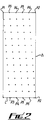
- the beam 3 falls continuously as a spot on the surface 5 of the pellet. Because the pellet is rotating and translating the spot traces out a helix. Discrete points along the helix are sampled by sampling the output of the detector 9 at suitable intervals, eg 40 times per second by the timer 12. This sampling procedure is illustrated in Figure 2.
- the rectangle having the opposite pairs of sides 1 and h in Figure 2 represents in two dimensions the overall curved surface area of the inspected pellet.
- the dimension 1 represents the length of the pellet and the dimension h represents the circumferential distance around the surface of the pellet.
- a sequence of relative depth measurement of the surface of the pellet is made at points P throughout the surface area. The sequence begins at the left hand end of the pellet (as represented in Figure 2) at a point P1 and then proceeds in a series of discrete steps following a helix until the right hand end of the pellet is reached at a point P2.
- plot on the surface of the pellet may contain a larger number of points P of measurement than as shown in Figure 2.
- Figures 3 and 4 show one form of device for rotating and translating the pellets 5 for use with the apparatus shown in Figure 1.
- the belt 23 is inclined by virtue of the roller 27 being at a height above the roller 25.
- a pellet 5 to be inspected is supported on the belt 23 by a plate 29.
- the angle of the plate 29 relative to the side edges of the belt 23 is adjustable but in Figure 4 the angle is adjusted so that one end 29a is lower than the other end 29b.
- the pellet 5 is caused to rotate by the movement of the belt 23 and to be moved laterally or translated in a direction X parallel to its axis by lateral slippage down the plate 29. If the angle of the plate 29 is changed so that the end 29a is above the end 29b then the lateral movement of the pellet 5 is in the opposite direction.
- the components comprising the laser 1, lens 4, lens 7, detector 9 and amplifier 11 may be provided as a commercially available height measuring system such as a Keyence LC 2000 laser displacement sensor. A resolution of 8 x 10 ⁇ 4mm may be satisfactorily achieved with such a system.
- the signal processing unit may comprise a Motorola 68000 processor running at 10 MHz. In operation the signal processor handles the sample processing in real time and then compares the results obtained in a decision tree, immediately after the pellet has been inspected, in order to indicate the nature of the fault observed. The pellet is rejected, if necessary, by operating a reject mechanism, and cumulative records are kept of the different types of defect detected, as well as the location in which the defect was found on the pellet eg edge, body, groove.
- an alternative form of the apparatus embodying the invention comprises rollers 41, 42 rotated by shafts 43, 44 driven by a drive unit 45 and moved linearly parallel to their own axes (as described with reference to Figure 6 below).
- Nuclear fuel pellets 47 are placed on the rollers 41, 42 the positions A, B etc defining inspection stations on the rollers 41, 42.
- the pellets 47 are obtained from a pick-up station 49 to which they are conveyed by a Cushion Transfer conveyer 51.
- the pellets 47 are picked up from the station 49 by a pick and place machine (not shown) which carries the pellets 47 along the directions indicated by dashed lines L1 and L2 etc (two only shown).
- each pellet 47 placed at the inspection station A is inspected in the same manner as described above with reference to Figures 1 and 2 using an inspection device 53 incorporating components similar to the laser 1, lens 4, lens 7 and detector 9.
- Lines 55, 57 indicate respectively the output and scattered laser beams in the inspection procedure at Station A.
- each pellet 47 placed at the inspection station defined by position B is inspected using an identical inspection device 59 and lines 61, 63 indicate respectively the output and scattered laser beams in the inspection procedure at Station B.
- the pellets are transferred by the pick and place machine either to an acceptance station 65 or to a reject station 67 as appropriate. Accepted pellets 47 at the acceptance station 67 are subsequently conveyed away by a Cushion Transfer conveyer 69.
- calibration pellets ie defect free 'model' pellets of known dimensions and also pellets having given defects of known dimenions
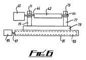
- Figure 6 shows how linear as well as rotary motion is applied to the rollers 41, 42 and therefore to the pellets 47 placed thereon.
- the drive unit 45 drives the rollers 41, 42 by the drive shafts 43, 44 (roller 42 and shaft 44 only shown being in Figure 6).
- the drive shaft 44 is supported through bearings 71, 73 by pillars 75, 77 respectively.
- the pillars 75, 77 are fixedly mounted on a base plate 79 which may be driven to move horizontally relative to a fixed base 81 by a leadscrew 83 incorporated within the base 81.
- the leadscrew 83 is driven by the rotary motion provided by a drive unit 85 acting through a drive shaft 87.
- the spot of the beam 61 traces a helical path across each inspected pellet 47.
- the spot has reached and passed the end of the pellet 47 it is inspecting the horizontal drive provided by the arrangement shown in Figure 6 is reversed to return the rollers 41, 42 to a start position.
Landscapes
- Physics & Mathematics (AREA)
- Health & Medical Sciences (AREA)
- Life Sciences & Earth Sciences (AREA)
- Chemical & Material Sciences (AREA)
- Analytical Chemistry (AREA)
- Biochemistry (AREA)
- General Health & Medical Sciences (AREA)
- General Physics & Mathematics (AREA)
- Immunology (AREA)
- Pathology (AREA)
- Investigating Materials By The Use Of Optical Means Adapted For Particular Applications (AREA)
- Monitoring And Testing Of Nuclear Reactors (AREA)
- Length Measuring Devices By Optical Means (AREA)
Applications Claiming Priority (2)
| Application Number | Priority Date | Filing Date | Title |
|---|---|---|---|
| GB9215832 | 1992-07-24 | ||
| GB929215832A GB9215832D0 (en) | 1992-07-24 | 1992-07-24 | The inspection of cylindrical objects |
Publications (1)
| Publication Number | Publication Date |
|---|---|
| EP0583092A1 true EP0583092A1 (de) | 1994-02-16 |
Family
ID=10719288
Family Applications (1)
| Application Number | Title | Priority Date | Filing Date |
|---|---|---|---|
| EP93305721A Withdrawn EP0583092A1 (de) | 1992-07-24 | 1993-07-21 | Untersuchung zylinderförmiger Gegenstände |
Country Status (4)
| Country | Link |
|---|---|
| US (1) | US5426309A (de) |
| EP (1) | EP0583092A1 (de) |
| JP (1) | JPH06167455A (de) |
| GB (1) | GB9215832D0 (de) |
Cited By (8)
| Publication number | Priority date | Publication date | Assignee | Title |
|---|---|---|---|---|
| WO1994025858A1 (en) * | 1993-05-05 | 1994-11-10 | British Nuclear Fuels Plc | Apparatus for the detection of surface defects |
| EP0693451A1 (de) * | 1994-07-11 | 1996-01-24 | B a r m a g AG | Verfahren zur optischen Vermessung der Spulenoberfläche von Fadenspulen |
| WO1997000438A1 (en) * | 1995-06-15 | 1997-01-03 | British Nuclear Fuels Plc | Inspecting the surface of an object |
| US5652432A (en) * | 1994-06-28 | 1997-07-29 | Mitsubishi Nuclear Fuel Co. | Cylindrical body inspection apparatus utilizing displacement information and reflected light information |
| WO2000016038A1 (en) * | 1998-09-10 | 2000-03-23 | Warner-Lambert Company | Apparatus for surface image sensing and surface inspection of three-dimensional structures |
| GB2377491A (en) * | 2001-04-26 | 2003-01-15 | Minebea Co Ltd | Apparatus for measuring distortion of a cylindrical body |
| GB2394042B (en) * | 2002-10-11 | 2005-09-07 | Statoil Asa | Method and apparatus for the inspection of surfaces |
| CN112414326A (zh) * | 2020-11-10 | 2021-02-26 | 浙江华睿科技有限公司 | 物体表面平整度的检测方法、装置、电子装置和存储介质 |
Families Citing this family (7)
| Publication number | Priority date | Publication date | Assignee | Title |
|---|---|---|---|---|
| US5760891A (en) * | 1995-08-25 | 1998-06-02 | Eastman Kodak Company | Wound web roll sidewall quality measurement |
| US6980301B2 (en) | 2002-07-25 | 2005-12-27 | Cubic Co., Ltd | Method and apparatus for three-dimensional surface morphometry |
| JP4837931B2 (ja) * | 2005-03-04 | 2011-12-14 | 愛知機械工業株式会社 | 検査装置及び検査方法 |
| CN106062539A (zh) * | 2014-02-04 | 2016-10-26 | Nsk美国有限公司 | 用于检测中等长度支撑的转向柱组件的设备和方法 |
| CN105980837A (zh) | 2014-02-04 | 2016-09-28 | Nsk美国有限公司 | 用于检验端部区域支撑的转向柱组件的设备和方法 |
| JP6598524B2 (ja) * | 2015-06-17 | 2019-10-30 | 一般財団法人電力中央研究所 | コンクリート含有物質の計測方法及び計測装置 |
| CN117434084A (zh) * | 2023-12-06 | 2024-01-23 | 四川万圣通实业有限公司 | 一种钢管的数字化检测装置及检测方法 |
Citations (4)
| Publication number | Priority date | Publication date | Assignee | Title |
|---|---|---|---|---|
| US4162126A (en) * | 1976-12-10 | 1979-07-24 | Hitachi, Ltd. | Surface detect test apparatus |
| US4226539A (en) * | 1976-12-24 | 1980-10-07 | Hitachi, Ltd. | Cylindrical body appearance inspection apparatus |
| US4532723A (en) * | 1982-03-25 | 1985-08-06 | General Electric Company | Optical inspection system |
| US4660970A (en) * | 1983-11-25 | 1987-04-28 | Carl-Zeiss-Stiftung | Method and apparatus for the contact-less measuring of objects |
Family Cites Families (4)
| Publication number | Priority date | Publication date | Assignee | Title |
|---|---|---|---|---|
| US4448680A (en) * | 1980-07-22 | 1984-05-15 | The United States Of America As Represented By The United States Department Of Energy | Apparatus and method for classifying fuel pellets for nuclear reactor |
| GB2181835B (en) * | 1985-10-01 | 1990-03-21 | Univ Liverpool | Monitoring device |
| FR2624600B1 (fr) * | 1987-12-09 | 1990-04-13 | Snecma | Procede et dispositif de controle de contours geometriques sans contact |
| NL9002869A (nl) * | 1990-12-27 | 1992-07-16 | Philips Nv | Inrichting voor het optisch meten van de hoogte van een oppervlak. |
-
1992
- 1992-07-24 GB GB929215832A patent/GB9215832D0/en active Pending
-
1993
- 1993-07-21 EP EP93305721A patent/EP0583092A1/de not_active Withdrawn
- 1993-07-23 US US08/095,860 patent/US5426309A/en not_active Expired - Fee Related
- 1993-07-23 JP JP5202573A patent/JPH06167455A/ja active Pending
Patent Citations (4)
| Publication number | Priority date | Publication date | Assignee | Title |
|---|---|---|---|---|
| US4162126A (en) * | 1976-12-10 | 1979-07-24 | Hitachi, Ltd. | Surface detect test apparatus |
| US4226539A (en) * | 1976-12-24 | 1980-10-07 | Hitachi, Ltd. | Cylindrical body appearance inspection apparatus |
| US4532723A (en) * | 1982-03-25 | 1985-08-06 | General Electric Company | Optical inspection system |
| US4660970A (en) * | 1983-11-25 | 1987-04-28 | Carl-Zeiss-Stiftung | Method and apparatus for the contact-less measuring of objects |
Non-Patent Citations (2)
| Title |
|---|
| BOTTLINGER ET AL.: "SIGNALE RICHTIG INTERPRETIEREN", LASER PRAXIS, no. 1, 1 June 1990 (1990-06-01), MUNCHEN, pages LS54 - LS55 * |
| GOODMAN: "SCANNING LASER ILLUMINATION SYSTEM", IBM TECHNICAL DISCLOSURE BULLETIN, vol. 27, no. 4B, 1 September 1984 (1984-09-01), pages 2643 - 2644 * |
Cited By (13)
| Publication number | Priority date | Publication date | Assignee | Title |
|---|---|---|---|---|
| WO1994025858A1 (en) * | 1993-05-05 | 1994-11-10 | British Nuclear Fuels Plc | Apparatus for the detection of surface defects |
| EP0690455B1 (de) * | 1994-06-28 | 2001-09-19 | Mitsubishi Nuclear Fuel Co. | Gerät zur Überprüfung von zylindrischen Gegenständen |
| US5652432A (en) * | 1994-06-28 | 1997-07-29 | Mitsubishi Nuclear Fuel Co. | Cylindrical body inspection apparatus utilizing displacement information and reflected light information |
| EP0693451A1 (de) * | 1994-07-11 | 1996-01-24 | B a r m a g AG | Verfahren zur optischen Vermessung der Spulenoberfläche von Fadenspulen |
| US5739904A (en) * | 1994-07-11 | 1998-04-14 | Barmag Ag | Method of optically measuring the surface of yarn packages |
| WO1997000438A1 (en) * | 1995-06-15 | 1997-01-03 | British Nuclear Fuels Plc | Inspecting the surface of an object |
| US5991017A (en) * | 1995-06-15 | 1999-11-23 | British Nuclear Fuels Plc | Inspecting the surface of an object |
| WO2000016038A1 (en) * | 1998-09-10 | 2000-03-23 | Warner-Lambert Company | Apparatus for surface image sensing and surface inspection of three-dimensional structures |
| US6393141B1 (en) | 1998-09-10 | 2002-05-21 | Warner-Lambert Company | Apparatus for surface image sensing and surface inspection of three-dimensional structures |
| GB2377491A (en) * | 2001-04-26 | 2003-01-15 | Minebea Co Ltd | Apparatus for measuring distortion of a cylindrical body |
| GB2377491B (en) * | 2001-04-26 | 2005-04-13 | Minebea Co Ltd | Apparatus for measuring distortion of cylindrical body |
| GB2394042B (en) * | 2002-10-11 | 2005-09-07 | Statoil Asa | Method and apparatus for the inspection of surfaces |
| CN112414326A (zh) * | 2020-11-10 | 2021-02-26 | 浙江华睿科技有限公司 | 物体表面平整度的检测方法、装置、电子装置和存储介质 |
Also Published As
| Publication number | Publication date |
|---|---|
| JPH06167455A (ja) | 1994-06-14 |
| US5426309A (en) | 1995-06-20 |
| GB9215832D0 (en) | 1992-09-09 |
Similar Documents
| Publication | Publication Date | Title |
|---|---|---|
| US5426309A (en) | Method and apparatus for inspecting the depth of the surface of cylindrical objects | |
| EP0649525B1 (de) | Vorrichtung zum nachweis von oberflächenfehlern | |
| JP3333048B2 (ja) | 円柱体の検査装置 | |
| JPS6355652B2 (de) | ||
| GB2252404A (en) | pellet inspection system | |
| EP0206501A2 (de) | Apparat zur Prüfung von Objekten | |
| EP0372788B1 (de) | Automatische Lehre | |
| US5991017A (en) | Inspecting the surface of an object | |
| US7746486B2 (en) | Pellet sorting by diameter measurement | |
| CA1057704A (en) | Photoelectric sorting of chipped nuclear fuel pellets | |
| JPS6055762B2 (ja) | 円筒物体外観検査装置 | |
| US4103776A (en) | Inspection machine for fuel pellets | |
| JPH07218442A (ja) | 円筒物検査装置 | |
| RU2155394C1 (ru) | Установка контроля и разбраковки тепловыделяющих элементов | |
| Jouaneh et al. | Measuring workpiece dimensions using a non-contact laser detector system | |
| JP2502159B2 (ja) | 核燃料ペレットの周面検査装置 | |
| JPH0479925B2 (de) | ||
| JP6989858B2 (ja) | 三針寸法測定装置及び三針寸法測定方法 | |
| RU2792704C1 (ru) | Способ автоматического контроля наличия комплектующих в твэлах и сплошности топливного столба и устройство для его реализации | |
| McLemore et al. | Automated in-line measurement of nuclear fuel pellets | |
| JP2796597B2 (ja) | 自動磁気探傷装置 | |
| JPH0342395Y2 (de) | ||
| JPS62115357A (ja) | 欠陥検査装置 | |
| JPS5834775B2 (ja) | 欠陥検査装置 | |
| Ponnambalam | Design and fabrication of automated inspection machine for spherical balls |
Legal Events
| Date | Code | Title | Description |
|---|---|---|---|
| PUAI | Public reference made under article 153(3) epc to a published international application that has entered the european phase |
Free format text: ORIGINAL CODE: 0009012 |
|
| AK | Designated contracting states |
Kind code of ref document: A1 Designated state(s): DE ES FR GB SE |
|
| 17P | Request for examination filed |
Effective date: 19940411 |
|
| R17P | Request for examination filed (corrected) |
Effective date: 19940317 |
|
| 17Q | First examination report despatched |
Effective date: 19960403 |
|
| STAA | Information on the status of an ep patent application or granted ep patent |
Free format text: STATUS: THE APPLICATION IS DEEMED TO BE WITHDRAWN |
|
| 18D | Application deemed to be withdrawn |
Effective date: 19981002 |