EP0583149A2 - Bouchon d'élimination pour cartouche filtrante - Google Patents
Bouchon d'élimination pour cartouche filtrante Download PDFInfo
- Publication number
- EP0583149A2 EP0583149A2 EP93306298A EP93306298A EP0583149A2 EP 0583149 A2 EP0583149 A2 EP 0583149A2 EP 93306298 A EP93306298 A EP 93306298A EP 93306298 A EP93306298 A EP 93306298A EP 0583149 A2 EP0583149 A2 EP 0583149A2
- Authority
- EP
- European Patent Office
- Prior art keywords
- plug
- grommet
- cartridge
- shoulder
- axial
- Prior art date
- Legal status (The legal status is an assumption and is not a legal conclusion. Google has not performed a legal analysis and makes no representation as to the accuracy of the status listed.)
- Granted
Links
Images


Classifications
-
- B—PERFORMING OPERATIONS; TRANSPORTING
- B01—PHYSICAL OR CHEMICAL PROCESSES OR APPARATUS IN GENERAL
- B01D—SEPARATION
- B01D27/00—Cartridge filters of the throw-away type
- B01D27/08—Construction of the casing
-
- B—PERFORMING OPERATIONS; TRANSPORTING
- B01—PHYSICAL OR CHEMICAL PROCESSES OR APPARATUS IN GENERAL
- B01D—SEPARATION
- B01D27/00—Cartridge filters of the throw-away type
- B01D27/10—Safety devices, e.g. by-passes
- B01D27/106—Anti-leakage or anti-return valves
Definitions
- This invention relates generally to filter cartridges such as employed for fuel filters for internal combustion engines. More particularly, the present invention relates to the disposal of the fuel filter cartridges employed for removing foreign particles and separating water from the fuel supply system of an internal combustion engine.
- a base mounts a disposable filter cartridge.
- the filter cartridge has an axial opening at one end to provide fuel communication between the fuel delivery system and the filter element disposed within the cartridge housing.
- a sealing grommet is disposed at the axial opening to provide a fluid tight seal.
- the fuel filter cartridges may house a single stage filter or a dual stage filter and may assume a wide variety of shapes and configurations.
- Fuel filter cartridges are typically replaced at pre-established usage intervals.
- the replaced filter which is discarded, may contain fuel, fuel residues and contaminants and filtered particulate matter. Because of the nature of the contents, the disposal of fuel filter cartridges has been made more difficult by increasing environmental considerations and by the mushrooming of governmental laws, rules and regulations relating to the disposal and recycling of spent petroleum based substances. Because the spent filter cartridge ordinarily contains fuel products, disposal of the cartridge may be subject to strict environmental and hazardous waste guidelines.
- a key stage in the disposal of the filter cartridge and/or the recycling of the cartridge is to ensure that the fluids and substances within the cartridge do not spill into the environment either at the replacement site or while the cartridge is being stored and/or transported for ultimate disposal and/or recycling.
- a filter cartridge comprising filter means disposed within a housing, said housing defining an axial opening at one end thereof, there being a generally sleeve-shaped grommet mounted at said opening extending into said housing, characterised in that the filter cartridge is provided with a plug for disposal in said grommet, said plug having a body with means for sealing with said grommet and a laterally extending portions for engagement with said grommet to restrict movement in both axial directions.
- the invention in a preferred form is a disposal plug for hermetically sealing a fuel filter cartridge of a type comprising a housing having an axial opening and a sleeve-like sealing grommet disposed in the opening.
- the disposal plug is insertable into the grommet in a removable temporary sealing mode and is reversible for insertion in a permanent activated sealing mode.
- the plug comprises a main body portion which may have either a generally cylindrical or a tapered configuration.
- the body portion forms a circumferential seal surface which diametrally seals against the interior seal surface of the grommet.
- the plug has a head having a forward tapered portion which is dimensioned and structured to pass through the sealing grommet at the interior of the cartridge.
- An annular radially projecting shoulder opposite the head is dimensioned to engage against the axial end of the sealing grommet upon insertion to prevent withdrawal of the plug.
- a stop projects radially from the main body. The stop is axially spaced from the shoulder and cooperates with the shoulder so that the plug is axially capturable relative to the grommet seal in either a removable non-activated mode or a permanent activated sealed mode.
- the plug When a new replacement cartridge replaces a spent cartridge, the plug is axially withdrawn from the cartridge. The axial orientation of the plug is reversed, and the plug is then inserted into the spent cartridge so that the head passes through the interiorly disposed end of the sealing grommet.
- the sealing body of the plug forms a diametral sealing interface with the surrounding grommet seal surface.
- the plug is axially captured in sealing relationship with the grommet by the shoulder and the axially spaced integral radially protruding stop on the main body. Withdrawal of the plug from the grommet is highly resisted by the axial engagement of the shoulder against the end of the grommet.
- the plug has a segmental cup-like configuration which closely exteriorly conforms to the interior surface of the sleeve-like sealing grommet.
- a seal rim proximate the closed normally lower end of the plug is defined by a pair of intersecting circumferential seal surfaces.
- the exterior surface of the plug also includes a tapered intermediate portion and a generally cylindrical enlarged upper portion. In a pre-usage mode, the cylindrical surface seals against the interior upper cylindrical sleeve-like surface of the grommet and a lower angled surface of the seal rim seals against an upper seal surface of the seal ring of the grommet.
- the grommet In an activated post-usage seal mode, the grommet is axially forced inwardly into the spent cartridge so that the exterior surface generally closely conforms to the interior surface of the sealing grommet with the upper angled surface of the plug seal rim sealing against a lower portion of grommet seal ring and the upper circumferential plug surface sealing against the upper interior portion of the grommet.
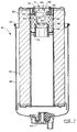
- a fuel filter cartridge is generally designated by the numeral 10.
- a disposal plug 12 is adapted for sealing the contents of the cartridge upon replacement with a new cartridge.
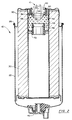
- the plug 12 is positionable in a removable mode prior to usage of the cartridge 10, such as illustrated in Figure 1, and is reversed and positionable in a permanent activated sealed mode after usage of the cartridge, such as illustrated in Figure 2.
- the fuel filter cartridge 10 is illustrated for purposes of describing the invention and is representative of numerous types of cartridges to which the invention has applicability.
- Fuel filter cartridge 10 for example, may be typically mounted to a base (not illustrated) and locked to the base by means of a retainer collar (not illustrated).
- the fuel filter cartridge may be adapted for incorporation into the fuel supply system of an internal combustion engine (not illustrated), such as a diesel engine for removing particulate matter from fuel and separating water from the fuel.
- an internal combustion engine not illustrated
- the invention may be employed in connection with filter cartridges having applications other than usage as a fuel filter.
- the disposable filter cartridge 10 comprises an axially symmetric can-like enclosure formed by a pair of opposed lower and upper cup-like sections 20 and 22. The sections are joined along a circumferential rolled seam 26.
- the upper section 22, which may be smaller in diameter than the lower section, is particularly adapted for reception by a receptacle of the base.
- the cartridge 10 employs a single filter element 30 of continuous fan-shaped, pleated configuration.
- the filter element is generally symmetrically disposed about the central axis of the cartridge.
- a drain valve 40 may be mounted at the lower end of the cartridge housing for draining water and/or other substances from the cartridge.
- the cartridge includes an axial opening 50 at one end of the cartridge.
- a sleeve-like sealing grommet 52 is mounted at the axial opening.
- the sealing grommet 52 has an integral inwardly disposed seal ring 54 which provides a primary diametral fluid seal against a closely received conduit (not illustrated).
- the generally cylindrical inner surface of the grommet provides a secondary seal along an axially extending interface with the conduit.
- the conduit is typically received through the opening for providing fluid communication between the base of the filter assembly and the disposable cartridge.
- a perforated center tube 55 extends from one axial end of the cartridge to an intermediate location.
- An insert 56 at the end of the center tube mounts a second sealing grommet 70 which for the illustrated cartridge may seal with a second coaxial conduit (not illustrated) extending from the base.
- the fuel flow path traverses generally axially and radially through the filter element to an outer portion interior of the cartridge and returns through an upper portion of the filter element for traversal through the axial opening to the base.
- the invention is not limited to the described single filter element, filter element configuration or flow path.
- the disposal plug 12 comprises a generally cylindrical body 60 which is dimensioned so that the grommet seal ring 54 diametrally fluidically seals against the cylindrical body.
- the plug includes a collar 62 at one end portion thereof which is dimensioned to radially extend from the main seal body so as to define an annular transverse shoulder 64.
- the forward portion of the collar has a tapered head 65.
- Axially displaced from the shoulder is an integral stop 66 which may take the form of a circular rim or one or more generally radial projections. The radial extent of the stop 66 is less than that of the shoulder 64.
- the stop 66 and the shoulder 64 function to maintain the sealing interface of the grommet ring 54 and the seal body 60 by resisting axial displacement of the plug from the grommet.
- the plug is highly resistant to withdrawal from the opening due to the potential engagement of the shoulder 64 against the axial end of the grommet.
- the stop 66 resists withdrawal of the plug but is designed to permit withdrawal under application of a moderate axial force to the plug.
- An axial tab 68 projects from the head 65 to facilitate grasping the plug.
- the plug 12 is preferably dimensioned so that upon initial shipping of the filter cartridge and prior to usage of the cartridge, the plug is inserted into the axial end of the cartridge and received in the grommet 52.
- the plug/grommet fit is sufficiently frictionally snug that the plug will be maintained with the cartridge but can be axially withdrawn with a moderate degree of force applied at the tab 68 to overcome the resistance provided by stop 66.
- a spent cartridge is removed from the filter assembly base.
- the plug (in the Figure 1 orientation) is removed from the new replacement cartridge and axially reversed to the Figure 2 orientation.
- the plug is then forcibly inserted into the spent cartridge opening so that the collar 62 clears the axial interior terminus of the grommet.
- the clearance of the collar may be facilitated by inserting the plug at an angle to the central grommet axis.
- the grommet has sufficient resilience to permit traversal of the collar and to engage the sealing body to diametrally fluidically seal with the plug.
- the Figure 2 reversed axial position of the plug in the opening is maintained by the shoulder 64 and the stop 66.
- a second embodiment of a disposal plug in accordance with the present invention is generally designated by the numeral 112.
- Plug 112 is received in sealing grommet 150 in cartridge pre-usage and post-usage axially spaced, seated sealing configurations illustrated respectively in Figures 3 and 4.
- Grommet 150 is generally similar in form and function to grommet 52.
- Plug 112 is a segmental, plastic cup-like member having a closed end 114 and a circumferential sealing rim 116 adjacent to the closed end.
- the sealing rim 116 is defined by a pair of intersecting tapered seal surfaces 120 and 122 which are generally complementary with axial portions of the grommet seal ring 154.
- the plug upwardly tapers from the sealing rim to an enlarged cylindrical seal surface 124.
- the rigidity of the plug is enhanced by four intersecting partitions 130 which generally axially extend from the closed end to adjacent the open end of the plug.
- the partitions 130 essentially define four congruent sectors as illustrated in Figure 5.
- the cylindrical surface 124 seals the upper interior portions of the grommet and lower surface 120 seats and seals against the inward upper sealing surface of the grommet seal ring 154.
- the plug is removed from the new cartridge, inserted into the replaced spent cartridge and axially forced to the Figure 4 seal position.
- Upper rim surface 122 engages the underside of the sealing grommet ring surface and the exterior contour of the plug generally sealingly conforms to the interior of the sealing grommet so that the cylindrical surface of the plug and grommet engage in generally surface-to-surface contact.
- the grommet seal ring 154 seats between the tapered exterior surface of the plug and rim surface 120.
- the plugs 12 and 112 which are preferably formed of a plastic material, hermetically seal the cartridge unit so that the cartridge and its contents may be transferred to a disposal station. At the disposal station, the cartridge is compressed to thereby force the substances retained within the cartridge to a collection control reservoir. The metal in the cartridge may then be recovered for recycling. The components of the grommet and plug may also be recovered for recycling.
- each plug 12 and 112 provide an efficient means for preventing spillage or contamination at the replacement site.
- each plug insures that the substances within the cartridge remain hermetically sealed during storage and transportation to the disposal site.
- the invention provides a new and improved disposal plug for a filter cartridge. It also provides a new and improved disposal plug which may be efficiently employed for hermetically sealing the contents of a filter cartridge.
- a new and improved disposal plug which may be mounted at the axial opening of a new filter cartridge and may be efficiently removed and inserted into a spent filter cartridge for permanent sealing therewith.
Landscapes
- Chemical & Material Sciences (AREA)
- Chemical Kinetics & Catalysis (AREA)
- Filtration Of Liquid (AREA)
- Closures For Containers (AREA)
- Filtering Of Dispersed Particles In Gases (AREA)
Applications Claiming Priority (2)
| Application Number | Priority Date | Filing Date | Title |
|---|---|---|---|
| US07/926,948 US5271836A (en) | 1992-08-10 | 1992-08-10 | Disposal plug for filter cartridge |
| US926948 | 1997-09-10 |
Publications (3)
| Publication Number | Publication Date |
|---|---|
| EP0583149A2 true EP0583149A2 (fr) | 1994-02-16 |
| EP0583149A3 EP0583149A3 (fr) | 1994-03-16 |
| EP0583149B1 EP0583149B1 (fr) | 1997-06-18 |
Family
ID=25453940
Family Applications (1)
| Application Number | Title | Priority Date | Filing Date |
|---|---|---|---|
| EP93306298A Expired - Lifetime EP0583149B1 (fr) | 1992-08-10 | 1993-08-10 | Bouchon d'élimination pour cartouche filtrante |
Country Status (5)
| Country | Link |
|---|---|
| US (1) | US5271836A (fr) |
| EP (1) | EP0583149B1 (fr) |
| JP (1) | JPH06170119A (fr) |
| DE (1) | DE69311647T2 (fr) |
| ES (1) | ES2102603T3 (fr) |
Families Citing this family (5)
| Publication number | Priority date | Publication date | Assignee | Title |
|---|---|---|---|---|
| US6364121B1 (en) * | 1999-07-19 | 2002-04-02 | Stanadyne Corporation | Filter cartridge with grommet spring |
| WO2007041559A2 (fr) * | 2005-09-30 | 2007-04-12 | Stanadyne Corporation | Structure de séparation et de filtration de l'eau |
| US8147691B2 (en) * | 2007-09-21 | 2012-04-03 | Baldwin Filters, Inc. | Filter cartridge housing attachment systems |
| WO2018067437A1 (fr) | 2016-10-03 | 2018-04-12 | Parker-Hannifin Corporation | Élément de filtre avec verrou de torsion et ensemble |
| CN110769913B (zh) | 2017-05-31 | 2021-11-16 | 帕克-汉尼芬公司 | 带有扭锁和/或滑动活塞的过滤元件、组件和方法 |
Family Cites Families (5)
| Publication number | Priority date | Publication date | Assignee | Title |
|---|---|---|---|---|
| US3133666A (en) * | 1962-01-17 | 1964-05-19 | Continental Can Co | Closure plug means |
| US3623628A (en) * | 1970-02-04 | 1971-11-30 | Microdot Inc | Oil filler plug |
| US4507199A (en) * | 1983-04-27 | 1985-03-26 | Carlisle Robert W | Oil filter unit and sealing device |
| US4741446A (en) * | 1986-12-29 | 1988-05-03 | Becton, Dickinson And Company | Computer generated stopper |
| US5171430A (en) * | 1991-05-17 | 1992-12-15 | Fleetguard, Inc. | Plastic filter |
-
1992
- 1992-08-10 US US07/926,948 patent/US5271836A/en not_active Expired - Lifetime
-
1993
- 1993-08-10 DE DE69311647T patent/DE69311647T2/de not_active Expired - Fee Related
- 1993-08-10 JP JP5218089A patent/JPH06170119A/ja active Pending
- 1993-08-10 EP EP93306298A patent/EP0583149B1/fr not_active Expired - Lifetime
- 1993-08-10 ES ES93306298T patent/ES2102603T3/es not_active Expired - Lifetime
Also Published As
| Publication number | Publication date |
|---|---|
| DE69311647T2 (de) | 1997-10-02 |
| US5271836A (en) | 1993-12-21 |
| DE69311647D1 (de) | 1997-07-24 |
| JPH06170119A (ja) | 1994-06-21 |
| EP0583149B1 (fr) | 1997-06-18 |
| EP0583149A3 (fr) | 1994-03-16 |
| ES2102603T3 (es) | 1997-08-01 |
Similar Documents
| Publication | Publication Date | Title |
|---|---|---|
| AU679771B2 (en) | Fluid filter cartridge with replaceable filter element | |
| RU2731926C2 (ru) | Конструкция жидкостного фильтра и связанные с ней способы | |
| US4376703A (en) | Oil filter cover | |
| EP2622202B1 (fr) | Système de filtre avec séparateur combustible-eau | |
| EP1311334B1 (fr) | Filtre a fluide ne fonctionnant qu'avec un element de filtre installe | |
| EP0528528B1 (fr) | Système de rétension pour filtre de carburant | |
| AU725948B2 (en) | Elongated filter system, filter element therefor and methods of making same | |
| US6471070B2 (en) | Ecological fuel filter cartridge and element | |
| CA2413992C (fr) | Ensemble de verrouillage et de prolongement pour element anti-goutte et recipient correspondant | |
| EP0529286B1 (fr) | Ensemble de filtrage avec récipient décanteur modulaire et ensemble décanteur modulaire | |
| EP2621603B1 (fr) | Système de filtre à cartouche muni d'un drain coopérant avec l'élément filtrant | |
| RU2743081C2 (ru) | Запорный механизм для очистки фильтрующего элемента | |
| CN113368590B (zh) | 过滤元件和过滤系统 | |
| DE3504984A1 (de) | Motoroelablass- und -sammelvorrichtung | |
| US5271836A (en) | Disposal plug for filter cartridge | |
| US20070221585A1 (en) | Collapsible Protective Cover for a Filter | |
| US5505849A (en) | Filtering apparatus | |
| WO2019217434A1 (fr) | Ensemble de verrouillage de cartouche filtrante | |
| EP3368186B1 (fr) | Système de liaison avec câble de verrouillage | |
| JPH067808U (ja) | カートリッジフィルター容器 | |
| HK1187566B (en) | Canister filter system with drain that cooperates with filter element |
Legal Events
| Date | Code | Title | Description |
|---|---|---|---|
| PUAI | Public reference made under article 153(3) epc to a published international application that has entered the european phase |
Free format text: ORIGINAL CODE: 0009012 |
|
| PUAL | Search report despatched |
Free format text: ORIGINAL CODE: 0009013 |
|
| AK | Designated contracting states |
Kind code of ref document: A2 Designated state(s): DE ES FR GB IT |
|
| AK | Designated contracting states |
Kind code of ref document: A3 Designated state(s): DE ES FR GB IT |
|
| 17P | Request for examination filed |
Effective date: 19940801 |
|
| 17Q | First examination report despatched |
Effective date: 19950707 |
|
| GRAG | Despatch of communication of intention to grant |
Free format text: ORIGINAL CODE: EPIDOS AGRA |
|
| GRAH | Despatch of communication of intention to grant a patent |
Free format text: ORIGINAL CODE: EPIDOS IGRA |
|
| GRAH | Despatch of communication of intention to grant a patent |
Free format text: ORIGINAL CODE: EPIDOS IGRA |
|
| GRAA | (expected) grant |
Free format text: ORIGINAL CODE: 0009210 |
|
| AK | Designated contracting states |
Kind code of ref document: B1 Designated state(s): DE ES FR GB IT |
|
| REF | Corresponds to: |
Ref document number: 69311647 Country of ref document: DE Date of ref document: 19970724 |
|
| REG | Reference to a national code |
Ref country code: ES Ref legal event code: FG2A Ref document number: 2102603 Country of ref document: ES Kind code of ref document: T3 |
|
| ITF | It: translation for a ep patent filed | ||
| ET | Fr: translation filed | ||
| PLBE | No opposition filed within time limit |
Free format text: ORIGINAL CODE: 0009261 |
|
| STAA | Information on the status of an ep patent application or granted ep patent |
Free format text: STATUS: NO OPPOSITION FILED WITHIN TIME LIMIT |
|
| 26N | No opposition filed | ||
| REG | Reference to a national code |
Ref country code: GB Ref legal event code: IF02 |
|
| PGFP | Annual fee paid to national office [announced via postgrant information from national office to epo] |
Ref country code: GB Payment date: 20060725 Year of fee payment: 14 |
|
| PGFP | Annual fee paid to national office [announced via postgrant information from national office to epo] |
Ref country code: ES Payment date: 20060817 Year of fee payment: 14 |
|
| PGFP | Annual fee paid to national office [announced via postgrant information from national office to epo] |
Ref country code: FR Payment date: 20060818 Year of fee payment: 14 |
|
| PGFP | Annual fee paid to national office [announced via postgrant information from national office to epo] |
Ref country code: DE Payment date: 20060829 Year of fee payment: 14 |
|
| GBPC | Gb: european patent ceased through non-payment of renewal fee |
Effective date: 20070810 |
|
| REG | Reference to a national code |
Ref country code: FR Ref legal event code: ST Effective date: 20080430 |
|
| PG25 | Lapsed in a contracting state [announced via postgrant information from national office to epo] |
Ref country code: DE Free format text: LAPSE BECAUSE OF NON-PAYMENT OF DUE FEES Effective date: 20080301 |
|
| PG25 | Lapsed in a contracting state [announced via postgrant information from national office to epo] |
Ref country code: FR Free format text: LAPSE BECAUSE OF NON-PAYMENT OF DUE FEES Effective date: 20070831 |
|
| REG | Reference to a national code |
Ref country code: ES Ref legal event code: FD2A Effective date: 20070811 |
|
| PG25 | Lapsed in a contracting state [announced via postgrant information from national office to epo] |
Ref country code: GB Free format text: LAPSE BECAUSE OF NON-PAYMENT OF DUE FEES Effective date: 20070810 |
|
| PGFP | Annual fee paid to national office [announced via postgrant information from national office to epo] |
Ref country code: IT Payment date: 20080827 Year of fee payment: 15 |
|
| PG25 | Lapsed in a contracting state [announced via postgrant information from national office to epo] |
Ref country code: ES Free format text: LAPSE BECAUSE OF NON-PAYMENT OF DUE FEES Effective date: 20070811 |
|
| PG25 | Lapsed in a contracting state [announced via postgrant information from national office to epo] |
Ref country code: IT Free format text: LAPSE BECAUSE OF NON-PAYMENT OF DUE FEES Effective date: 20080810 |