EP0583193A2 - Verbesserung der Anordnung einer Pumpe in einem Behälter - Google Patents
Verbesserung der Anordnung einer Pumpe in einem Behälter Download PDFInfo
- Publication number
- EP0583193A2 EP0583193A2 EP93402002A EP93402002A EP0583193A2 EP 0583193 A2 EP0583193 A2 EP 0583193A2 EP 93402002 A EP93402002 A EP 93402002A EP 93402002 A EP93402002 A EP 93402002A EP 0583193 A2 EP0583193 A2 EP 0583193A2
- Authority
- EP
- European Patent Office
- Prior art keywords
- pump
- section
- pump body
- container
- neck
- Prior art date
- Legal status (The legal status is an assumption and is not a legal conclusion. Google has not performed a legal analysis and makes no representation as to the accuracy of the status listed.)
- Granted
Links
Images


Classifications
-
- B—PERFORMING OPERATIONS; TRANSPORTING
- B05—SPRAYING OR ATOMISING IN GENERAL; APPLYING FLUENT MATERIALS TO SURFACES, IN GENERAL
- B05B—SPRAYING APPARATUS; ATOMISING APPARATUS; NOZZLES
- B05B11/00—Single-unit hand-held apparatus in which flow of contents is produced by the muscular force of the operator at the moment of use
- B05B11/01—Single-unit hand-held apparatus in which flow of contents is produced by the muscular force of the operator at the moment of use characterised by the means producing the flow
- B05B11/10—Pump arrangements for transferring the contents from the container to a pump chamber by a sucking effect and forcing the contents out through the dispensing nozzle
- B05B11/1042—Components or details
- B05B11/1043—Sealing or attachment arrangements between pump and container
- B05B11/1046—Sealing or attachment arrangements between pump and container the pump chamber being arranged substantially coaxially to the neck of the container
- B05B11/1047—Sealing or attachment arrangements between pump and container the pump chamber being arranged substantially coaxially to the neck of the container the pump being preassembled as an independent unit before being mounted on the container
-
- B—PERFORMING OPERATIONS; TRANSPORTING
- B05—SPRAYING OR ATOMISING IN GENERAL; APPLYING FLUENT MATERIALS TO SURFACES, IN GENERAL
- B05B—SPRAYING APPARATUS; ATOMISING APPARATUS; NOZZLES
- B05B11/00—Single-unit hand-held apparatus in which flow of contents is produced by the muscular force of the operator at the moment of use
- B05B11/01—Single-unit hand-held apparatus in which flow of contents is produced by the muscular force of the operator at the moment of use characterised by the means producing the flow
- B05B11/10—Pump arrangements for transferring the contents from the container to a pump chamber by a sucking effect and forcing the contents out through the dispensing nozzle
- B05B11/1001—Piston pumps
- B05B11/1016—Piston pumps the outlet valve having a valve seat located downstream a movable valve element controlled by a pressure actuated controlling element
- B05B11/1018—Piston pumps the outlet valve having a valve seat located downstream a movable valve element controlled by a pressure actuated controlling element and the controlling element cooperating with means for opening or closing the inlet valve
Definitions
- the present invention relates to an improvement in the assembly of a pump in a tank.
- the pumps in question are miniaturized pumps, generally actuated by a finger of a hand, for dispensing or spraying a fluid, liquid or pasty product such as a perfume, a cosmetic product, or a pharmaceutical product.
- Such a tower generally has a substantially cylindrical side wall which surrounds the pump body in the vicinity of its second end, said side wall of the tower being extended radially outwards by a wheelbase which can be fixed on the neck of a container by wedging between a screw cap and said container neck.
- This mounting method has the disadvantage that a substantial part of the pump body protrudes above the neck of the container, which increases the size of the device.
- a screw cap which has an internal axial through passage, said passage comprising a first substantially cylindrical section towards the outside of the container, and a second narrower section towards the inside of the container, said first and second sections defining a shoulder directed towards the outside of the container, the pump body being engaged in said second section and said collar being placed in abutment against the shoulder of the plug, and said pump body collar being held in said second section of the passage of the plug by an annular locking ring, force-fitted into a side wall cylindrical plug.
- this assembly it is generally necessary to interpose a flat seal between the collar of the pump body and the locking ring.
- This method of attachment is advantageous, since the pump body projects very slightly above the neck of the tank. However, it requires the use of a locking ring and an additional seal.
- the object of the present invention is to propose a method of mounting a pump on a stopper or a container neck, which results in a space requirement which is as small as in a mounting with a locking ring, but which is simpler and less expensive than said mounting by locking ring.
- a pump can be fixed in the same way as described above, on the neck of a container, provided that the neck has the characteristics already described for the stopper.
- the neck is metallic, for example when the pump is fixed to a deformable aluminum tube, said neck is matted after assembly of the pump, to prevent any exit of said pump outside said neck.
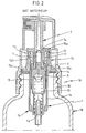
- FIG. 1 represents a pump of the general type disclosed in documents FR-A-2,305,241 and FR-A-2,314,772, as well as in the American patent corresponds US-A-4,025,046.
- the pump presented comprises a body pump 1 with side wall cylindrical 1a which extends between a first end 1b and a second end 1c of the pump body.
- the first end 1b forms a bottom which comprises an inlet orifice 1d of the pump, while the second end 1c is open and has an external collar 12.
- Inside the pump body is mounted axially sliding a piston 2, secured to a push rod 3, which passes through the first end 1c of the pump body.
- the push rod 3 is crossed axially by an outlet channel 3a, which has a narrowing 7a.
- valve 6 which comprises a needle 7 engaged in the outlet channel 3a, and a skirt 8 which extends axially towards the first end 1b of the pump body.
- the pump body further comprises a tubular nozzle 4 which extends axially inside the side wall 1a, from the first end 1b.
- a spring 10 biases the valve towards the second end 1c of the side wall l of the pump body, which tends to apply with sealing the needle 7 against the narrowing 7a of the outlet channel 3a, and to push the piston 2 towards the end 1c.
- a cylindrical ferrule 11 is force fitted or snapped or otherwise fixed in the second end 1c, so as to limit the movement of the piston 2 towards said end 1c, thereby defining a rest position of the pump.
- the skirt 8 When the pump is in the rest position, the skirt 8 is not engaged on the nozzle 4. When the rod 3 is pushed inside the pump body, the skirt 8 engages on the nozzle 4, thereby closing the inlet 1b. When the pressure prevailing inside the pump body is sufficient, the needle 7 comes off from the constriction 7a, allowing the dose of substance included in the pump body to escape through the outlet channel 3a.
- the pump is provided with a crimpable metal cup 13, which can be crimped on the one hand on the collar 12 and the ferrule 11, and on the other hand on the neck of a container. (not shown), conventionally.
- an annular flat seal 14 made of elastomer is interposed between the metal capsule 13 and the neck of a container.
- FIG. 2 represents another fixing method known in the prior art.
- the pump represented in FIG. 2 is similar to that of FIG. 1. It is adapted on a neck 18 of a container 19, by means of a cap 16 screwable onto said neck.
- the ferrule 11 of the pump is extended externally by a spinner 15, comprising a first annular wall 15a, extending radially outward from the ferrule 11, as far as the neck 12 of the pump body, said first annular wall 15a being extended axially towards the neck of the container by a lateral annular wall 15b, up to a wheelbase 15c.
- the plug 16 has an inner flange 16a, which comes to tighten the wheelbase 15c against the neck 18 of the container during assembly.
- a flat annular seal 14 is disposed between the wheelbase 15c and the neck 18.
- FIG. 3 it is also known to assemble a pump body 1 on a plug 20 screwable on the neck of a container, by providing in the plug 20 an axial internal passage 21 which passes through it, said axial passage 21 comprising a first cylindrical section 22, further from the container when the cap is screwed onto the neck of the container, and a second narrower section 23, closer to the container when the cap is screwed onto the container.
- the first section 22 has a diameter substantially equal to the outside diameter of the collar 12 of the pump body.
- the internal passage 21 defines a shoulder 24, directed towards the outside of the container.
- the collar 12 of the pump body is located inside the first section 22 of the interior passage 21, while the side wall 1a of the pump body is engaged inside the second section 23 of the interior passage 21 of the plug.
- the collar 12 and the ferrule 11 of the pump are held in the first section 22 of the passage 21, by an annular locking ring 25.
- the plug 20 has an annular wall 26, formed around the interior passage 21, and which extends axially away from the container.
- the annular locking ring 25 is forcibly fitted inside the side wall 26, and said annular ring 25 has an axial central orifice 25a, of diameter less than the diameter of the first section 22 of the interior passage 21, so as to maintain the collar 12 of the pump body.
- An annular flat seal 27 is disposed on the locking ring 25, so as to perfect the seal between the ring on the one hand, the pump body and the plug on the other hand.
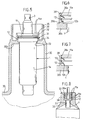
- FIG. 4 shows an embodiment of the fixing method according to the invention.
- the pump shown in FIG. 4 is identical to that of the preceding figures, but the invention is not limited to this particular type of pump, the important thing being that the pump comprises a pump body provided at its upper end with an outer collar and a ferrule preventing the piston from exiting the pump under the effect of the internal return spring.
- the pump body is fixed to the neck of a container (not shown) by means of a plug 20.
- the plug 20 has a skirt 20a provided with an internal thread, which allows the plug to be screwed onto the neck of the container. .
- the plug 20 further comprises an internal annular flange 20b, which extends radially inwards from the skirt 20a, to a central orifice 22 which has a diameter substantially equal to or slightly greater than the external diameter of the wall lateral of the pump body, but less than the external diameter of the collar 12 of the pump body.
- a cylindrical side wall 28 extends axially from the flange 20b, away from the container, said side wall 28 surrounding the orifice 22. The diameter inside of the side wall 28 is substantially equal to the outside diameter of the collar 12.
- the orifice 22 and the side wall 28 define an axial internal passage which passes through the plug, said passage comprising a first section 23 delimited by the side wall 28 , and a second section 22 corresponding to the central orifice of the flange 20b. Between the sections 22 and 23 is defined a shoulder 24 directed towards the outside of the container.
- the plug 20 further comprises a cylindrical wall 26, which extends axially away from the container substantially in the extension of the skirt 20a.
- the side wall 26 has essentially an aesthetic purpose and a purpose of guiding a pusher mounted on the rod 3 of the pump.
- the ferrule 11 has a radial crown 11a which has a diameter slightly greater than the inside diameter of the side wall 28.
- the radial crown 11a is forced into the interior of the side wall 28 and said crown 11a keeps the pump body fixed in the plug 20, by blocking the shoulder 12 inside the housing defined by the side wall 28 and the shoulder 24.
- the crown 11a has a notch-shaped peripheral outer edge 11b, having a sliding chamfered surface 11c, closer to the container, and a stop surface 11d further from the container, and substantially perpendicular to the axis of revolution of the ferrule.
- the ferrule 11 is made of a material harder than the side wall 28, so that the notch 11b can bite inside the side wall 28, making the assembly even more solid.
- the plug 20 can be made of polypropylene, while the ferrule 11 is made of harder acetal resin.
- the pump is of the type operating with air intake, that is to say that it returns air to the container on each actuation.
- the ferrule 11 may have an axial groove 11f and the collar 12 may have an axial groove 12a, so as to communicate the interior of the container with the atmosphere during actuation of the pump, as it is well known in the state of the art.
- the method of attachment shown in Figure 4 is also applicable to pumps operating without air intake, that is to say in the present case, pumps not having the grooves 11f and 12a.
- the container 39 which can for example be a deformable tube adapted to flatten progressively under the effect of the suction of the pump, comprises a neck 30 provided with an inner annular flange 30b, which s 'extends radially inwards to a central orifice 33.
- the internal diameter of the central orifice 33 is substantially equal to or slightly greater than the external diameter of the side wall 1a of the pump body.
- a cylindrical side wall 38 extends axially towards the outside of the container from the flange 30b, surrounding the orifice 33.
- the cylindrical side wall 38 has an inside diameter substantially equal to the outside diameter of the collar 12.
- the wall 38 and the orifice 33 thus define an axial internal passage which passes through the neck 30, with a first section 32 inside the side wall 38, and a second section 33 corresponding to the central orifice of the flange 30b. Between the sections 32 and 33, a shoulder 34 is defined, directed towards the outside of the container.
- the pump body is fixed as in the example of FIG. 4 inside the side wall 38, by means of two superimposed radial rings 11a of the ferrule 11, which have an outside diameter slightly greater than the inside diameter of the side wall 38, and which are forced into said side wall 38.
- the container 39 is a deformable tube, it can be made of plastic, or optionally of metal, for example aluminum.
- the shape of the neck 30 will generally be simpler, the side wall 38 being generally thicker, and the neck 30 not having the second side wall 36.
- it can it is advantageous to mat the free end of the side wall 38, so as to form an internal bead 38a which prevents any exit of the pump body from said side wall 38.
- the crown 11a of the ferrule can not be forced-fitted, but snapped inside the side wall 38, said side wall having an internal bead 38a which allows the snap-fastening.
- the side wall 38 may optionally include one or more sealing beads 38b, which bear against the collar 12 of the pump body 1, when the pump is operating without air intake.
- the neck 12 also has a notch shape, with a chamfered surface 12b close to the reservoir, the sealing bead 38b pressing against said chamfered surface 12b.
- FIG. 7 represents a variant of FIG. 6 in which the collar 12 also has a notch shape with an external edge 12c in sealed contact with the side wall 38.
Landscapes
- Closures For Containers (AREA)
- Reciprocating Pumps (AREA)
- Containers And Packaging Bodies Having A Special Means To Remove Contents (AREA)
Applications Claiming Priority (2)
| Application Number | Priority Date | Filing Date | Title |
|---|---|---|---|
| FR9209881A FR2694607B1 (fr) | 1992-08-10 | 1992-08-10 | Perfectionnement à l'assemblage d'une pompe dans un réservoir. |
| FR9209881 | 1992-08-10 |
Publications (3)
| Publication Number | Publication Date |
|---|---|
| EP0583193A2 true EP0583193A2 (de) | 1994-02-16 |
| EP0583193A3 EP0583193A3 (de) | 1994-03-16 |
| EP0583193B1 EP0583193B1 (de) | 1997-05-28 |
Family
ID=9432756
Family Applications (1)
| Application Number | Title | Priority Date | Filing Date |
|---|---|---|---|
| EP93402002A Expired - Lifetime EP0583193B1 (de) | 1992-08-10 | 1993-08-04 | Verbesserung der Anordnung einer Pumpe in einem Behälter |
Country Status (6)
| Country | Link |
|---|---|
| US (1) | US5377881A (de) |
| EP (1) | EP0583193B1 (de) |
| JP (1) | JP3528133B2 (de) |
| DE (1) | DE69311022T2 (de) |
| ES (1) | ES2105162T3 (de) |
| FR (1) | FR2694607B1 (de) |
Cited By (1)
| Publication number | Priority date | Publication date | Assignee | Title |
|---|---|---|---|---|
| FR2719292A1 (fr) * | 1994-04-29 | 1995-11-03 | Valois Sa | Dispositif et procédé de fixation d'un organe de dosage dans un récipient contenant du produit à distribuer. |
Families Citing this family (13)
| Publication number | Priority date | Publication date | Assignee | Title |
|---|---|---|---|---|
| US5669530A (en) * | 1995-08-18 | 1997-09-23 | Aptargroup, Inc. | Mounting systems accomodating a manually actuatable pump for fixed or variable dose operation |
| US5850948A (en) | 1996-09-13 | 1998-12-22 | Valois S.A. | Finger-operable pump with piston biasing post |
| DE19739989A1 (de) * | 1997-09-11 | 1999-03-18 | Pfeiffer Erich Gmbh & Co Kg | Spender für Medien |
| DE19739990A1 (de) * | 1997-09-11 | 1999-03-18 | Pfeiffer Erich Gmbh & Co Kg | Spender für Medien |
| US5918778A (en) * | 1997-12-19 | 1999-07-06 | Emson, Inc. | Pump and pump securing device which maintains consistent dosage accuracy, and method of securing a pump to a container |
| JP2000344260A (ja) * | 1999-06-08 | 2000-12-12 | Valois Sa | 流体分与器 |
| JP3942020B2 (ja) * | 2002-05-23 | 2007-07-11 | 株式会社吉野工業所 | 蓄圧式ポンプおよびそのモジュール |
| DE10130368A1 (de) * | 2001-06-23 | 2003-01-16 | Pfeiffer Erich Gmbh & Co Kg | Spender zum Austragen eines fluidischen Mediums |
| FR2862106B1 (fr) * | 2003-11-07 | 2007-08-24 | Valois Sas | Pompe de distribution de produit fluide. |
| FR2885887B1 (fr) | 2005-05-20 | 2010-11-05 | Rexam Dispensing Sys | Pompe a pointeau pour la distribution de produit liquide |
| FR2913731B1 (fr) * | 2007-03-12 | 2013-08-09 | Valois Sas | Pompe de distribution de produit fluide et distributeur comportant une telle pompe |
| CN104549827B (zh) * | 2015-01-26 | 2017-08-04 | 中山市美捷时包装制品有限公司 | 一种喷雾泵封杯与锁紧盖配合结构及喷雾泵 |
| CN106275801A (zh) * | 2016-10-13 | 2017-01-04 | 中山市联昌喷雾泵有限公司 | 一种用于罐的泵阀 |
Family Cites Families (5)
| Publication number | Priority date | Publication date | Assignee | Title |
|---|---|---|---|---|
| FR2620052B1 (fr) * | 1987-09-09 | 1990-04-27 | Valois | Vaporisateur du type pompe manuelle a precompression pour utilisation avec un gaz propulseur |
| IT1221790B (it) * | 1988-04-12 | 1990-07-12 | Sar Spa | Dispositivo,particolarmente per pompetta a mano,per l'erogazione di una quantita' prestabilita di prodotti in pasta o liquidi contenuti in flaconi |
| US5033655A (en) * | 1989-02-15 | 1991-07-23 | Liquid Molding Systems Inc. | Dispensing package for fluid products and the like |
| FR2661157B1 (fr) * | 1990-04-19 | 1993-08-13 | Jumel Bernard | Systeme doseur sans bague destine a etre emmanche a force a l'interieur d'un col de recipient. |
| US5158211A (en) * | 1990-08-30 | 1992-10-27 | Philip Meshberg | Fluid dispensing unit retainer |
-
1992
- 1992-08-10 FR FR9209881A patent/FR2694607B1/fr not_active Expired - Fee Related
-
1993
- 1993-08-04 DE DE69311022T patent/DE69311022T2/de not_active Expired - Fee Related
- 1993-08-04 ES ES93402002T patent/ES2105162T3/es not_active Expired - Lifetime
- 1993-08-04 EP EP93402002A patent/EP0583193B1/de not_active Expired - Lifetime
- 1993-08-05 US US08/102,261 patent/US5377881A/en not_active Expired - Lifetime
- 1993-08-10 JP JP21683693A patent/JP3528133B2/ja not_active Expired - Fee Related
Cited By (3)
| Publication number | Priority date | Publication date | Assignee | Title |
|---|---|---|---|---|
| FR2719292A1 (fr) * | 1994-04-29 | 1995-11-03 | Valois Sa | Dispositif et procédé de fixation d'un organe de dosage dans un récipient contenant du produit à distribuer. |
| WO1995029760A1 (fr) * | 1994-04-29 | 1995-11-09 | Valois S.A. | Dispositif et procede de fixation d'un organe de dosage dans un recipient contenant du produit a distribuer |
| US5845819A (en) * | 1994-04-29 | 1998-12-08 | Valois S.A. | Method and device for fixing a metering member in a receptacle containing a substance to be dispensed |
Also Published As
| Publication number | Publication date |
|---|---|
| EP0583193A3 (de) | 1994-03-16 |
| JP3528133B2 (ja) | 2004-05-17 |
| US5377881A (en) | 1995-01-03 |
| JPH07165250A (ja) | 1995-06-27 |
| FR2694607B1 (fr) | 1994-10-07 |
| EP0583193B1 (de) | 1997-05-28 |
| DE69311022T2 (de) | 1998-01-15 |
| ES2105162T3 (es) | 1997-10-16 |
| DE69311022D1 (de) | 1997-07-03 |
| FR2694607A1 (fr) | 1994-02-11 |
Similar Documents
| Publication | Publication Date | Title |
|---|---|---|
| EP0583193B1 (de) | Verbesserung der Anordnung einer Pumpe in einem Behälter | |
| EP0453357B1 (de) | Sprüh- und Dosiervorrichtung | |
| EP1171367B1 (de) | Befestigungselement für flüssigkeitsabgabevorrichtungen und abgabevorrichtung die ein solches element enthält | |
| EP2641660B1 (de) | Verfahren zum anbringen einer pumpe an einem tankstutzen | |
| EP3898003B1 (de) | Vorrichtung zur ausgabe eines fluidprodukts | |
| WO1999011387A1 (fr) | Dispositif de distribution a bague de fixation a emmanchement conique | |
| EP2069072B1 (de) | Spenderanordnung und spender für ein flüssigprodukt mit derartiger spenderanordnung | |
| EP1701800A1 (de) | Flüssigkeitsspendereinheit und behälter mit einer solchen einheit | |
| EP1814672B1 (de) | Ein auslassventil und eine rückstellfeder für eine abgabevorrichtung bildendes flexibles teil | |
| FR3047186A1 (fr) | Dispositif de purge d'air pour distributeur de produit liquide sans reprise d'air | |
| EP1583613B1 (de) | Abgabevorrichtung für flüssigkeiten | |
| EP1963027B1 (de) | Fluidproduktabgabeglied und damit versehene abgabevorrichtung | |
| WO2024028556A1 (fr) | Dispositif de distribution de produit fluide | |
| EP0605275B1 (de) | Anordnung zur Zerstäubung einer Flüssigkeit mit einer Vordruckpumpe | |
| WO2003039975A1 (fr) | Fixation indemontable d'un dispositif de distribution | |
| EP1919799B1 (de) | Fluidproduktabgabeventil | |
| FR2738557A1 (fr) | Dispositif de montage d'un organe de distribution sur le col d'un recipient | |
| FR2678906A1 (fr) | Dispositif pour projeter une dose predeterminee d'un produit fluide, et son procede de remplissage. | |
| EP0499537B1 (de) | Vorrichtung zur Zerstäubung oder Abgabe eines flüssigen Produktes mit einem Schiebesteigrohr im Saugrohr | |
| EP1703985B1 (de) | Fluidproduktspender | |
| EP0275754B1 (de) | Ausgeber mit Tropfvorrichtung | |
| WO2026046940A1 (fr) | Dispositif de distribution de produit fluide comportant une pompe | |
| WO2001083117A1 (fr) | Dispositif de distribution de produit fluide | |
| FR2772728A1 (fr) | Organe de distribution a poche souple |
Legal Events
| Date | Code | Title | Description |
|---|---|---|---|
| PUAI | Public reference made under article 153(3) epc to a published international application that has entered the european phase |
Free format text: ORIGINAL CODE: 0009012 |
|
| PUAL | Search report despatched |
Free format text: ORIGINAL CODE: 0009013 |
|
| AK | Designated contracting states |
Kind code of ref document: A2 Designated state(s): DE ES FR GB IT |
|
| AK | Designated contracting states |
Kind code of ref document: A3 Designated state(s): DE ES FR GB IT |
|
| 17P | Request for examination filed |
Effective date: 19940914 |
|
| 17Q | First examination report despatched |
Effective date: 19960416 |
|
| GRAG | Despatch of communication of intention to grant |
Free format text: ORIGINAL CODE: EPIDOS AGRA |
|
| GRAH | Despatch of communication of intention to grant a patent |
Free format text: ORIGINAL CODE: EPIDOS IGRA |
|
| GRAH | Despatch of communication of intention to grant a patent |
Free format text: ORIGINAL CODE: EPIDOS IGRA |
|
| GRAA | (expected) grant |
Free format text: ORIGINAL CODE: 0009210 |
|
| AK | Designated contracting states |
Kind code of ref document: B1 Designated state(s): DE ES FR GB IT |
|
| REF | Corresponds to: |
Ref document number: 69311022 Country of ref document: DE Date of ref document: 19970703 |
|
| ITF | It: translation for a ep patent filed | ||
| RAP2 | Party data changed (patent owner data changed or rights of a patent transferred) |
Owner name: VALOIS S.A. |
|
| GBT | Gb: translation of ep patent filed (gb section 77(6)(a)/1977) |
Effective date: 19970901 |
|
| REG | Reference to a national code |
Ref country code: ES Ref legal event code: FG2A Ref document number: 2105162 Country of ref document: ES Kind code of ref document: T3 |
|
| PLBE | No opposition filed within time limit |
Free format text: ORIGINAL CODE: 0009261 |
|
| STAA | Information on the status of an ep patent application or granted ep patent |
Free format text: STATUS: NO OPPOSITION FILED WITHIN TIME LIMIT |
|
| 26N | No opposition filed | ||
| ITPR | It: changes in ownership of a european patent |
Owner name: CAMBIO NOME EPO;VALOIS S.A. |
|
| REG | Reference to a national code |
Ref country code: GB Ref legal event code: IF02 |
|
| PGFP | Annual fee paid to national office [announced via postgrant information from national office to epo] |
Ref country code: DE Payment date: 20060808 Year of fee payment: 14 |
|
| PGFP | Annual fee paid to national office [announced via postgrant information from national office to epo] |
Ref country code: GB Payment date: 20060811 Year of fee payment: 14 |
|
| PGFP | Annual fee paid to national office [announced via postgrant information from national office to epo] |
Ref country code: ES Payment date: 20060818 Year of fee payment: 14 |
|
| PGFP | Annual fee paid to national office [announced via postgrant information from national office to epo] |
Ref country code: IT Payment date: 20060831 Year of fee payment: 14 |
|
| GBPC | Gb: european patent ceased through non-payment of renewal fee |
Effective date: 20070804 |
|
| PG25 | Lapsed in a contracting state [announced via postgrant information from national office to epo] |
Ref country code: DE Free format text: LAPSE BECAUSE OF NON-PAYMENT OF DUE FEES Effective date: 20080301 |
|
| REG | Reference to a national code |
Ref country code: ES Ref legal event code: FD2A Effective date: 20070806 |
|
| PG25 | Lapsed in a contracting state [announced via postgrant information from national office to epo] |
Ref country code: GB Free format text: LAPSE BECAUSE OF NON-PAYMENT OF DUE FEES Effective date: 20070804 |
|
| PG25 | Lapsed in a contracting state [announced via postgrant information from national office to epo] |
Ref country code: ES Free format text: LAPSE BECAUSE OF NON-PAYMENT OF DUE FEES Effective date: 20070806 |
|
| PG25 | Lapsed in a contracting state [announced via postgrant information from national office to epo] |
Ref country code: IT Free format text: LAPSE BECAUSE OF NON-PAYMENT OF DUE FEES Effective date: 20070804 |
|
| PGFP | Annual fee paid to national office [announced via postgrant information from national office to epo] |
Ref country code: FR Payment date: 20110907 Year of fee payment: 19 |
|
| REG | Reference to a national code |
Ref country code: FR Ref legal event code: ST Effective date: 20130430 |
|
| PG25 | Lapsed in a contracting state [announced via postgrant information from national office to epo] |
Ref country code: FR Free format text: LAPSE BECAUSE OF NON-PAYMENT OF DUE FEES Effective date: 20120831 |