EP0583225B1 - Verbesserte Vorrichtung zum Ausgeben von Warenstücken - Google Patents
Verbesserte Vorrichtung zum Ausgeben von Warenstücken Download PDFInfo
- Publication number
- EP0583225B1 EP0583225B1 EP93830294A EP93830294A EP0583225B1 EP 0583225 B1 EP0583225 B1 EP 0583225B1 EP 93830294 A EP93830294 A EP 93830294A EP 93830294 A EP93830294 A EP 93830294A EP 0583225 B1 EP0583225 B1 EP 0583225B1
- Authority
- EP
- European Patent Office
- Prior art keywords
- items
- stack
- shutter
- dispensing apparatus
- pusher
- Prior art date
- Legal status (The legal status is an assumption and is not a legal conclusion. Google has not performed a legal analysis and makes no representation as to the accuracy of the status listed.)
- Expired - Lifetime
Links
- 230000007246 mechanism Effects 0.000 claims description 13
- 238000003780 insertion Methods 0.000 claims description 7
- 230000037431 insertion Effects 0.000 claims description 7
- 230000000284 resting effect Effects 0.000 claims description 5
- 230000009471 action Effects 0.000 claims description 3
- 238000006073 displacement reaction Methods 0.000 claims 1
- 238000012423 maintenance Methods 0.000 description 2
- 230000004888 barrier function Effects 0.000 description 1
- 235000019504 cigarettes Nutrition 0.000 description 1
- 235000009508 confectionery Nutrition 0.000 description 1
- 230000005484 gravity Effects 0.000 description 1
- 238000009434 installation Methods 0.000 description 1
- 230000004048 modification Effects 0.000 description 1
- 238000012986 modification Methods 0.000 description 1
- 230000004044 response Effects 0.000 description 1
- 230000009466 transformation Effects 0.000 description 1
Images



Classifications
-
- G—PHYSICS
- G07—CHECKING-DEVICES
- G07F—COIN-FREED OR LIKE APPARATUS
- G07F9/00—Details other than those peculiar to special kinds or types of apparatus
- G07F9/02—Devices for alarm or indication, e.g. when empty; Advertising arrangements in coin-freed apparatus
-
- G—PHYSICS
- G07—CHECKING-DEVICES
- G07F—COIN-FREED OR LIKE APPARATUS
- G07F11/00—Coin-freed apparatus for dispensing, or the like, discrete articles
- G07F11/02—Coin-freed apparatus for dispensing, or the like, discrete articles from non-movable magazines
- G07F11/04—Coin-freed apparatus for dispensing, or the like, discrete articles from non-movable magazines in which magazines the articles are stored one vertically above the other
- G07F11/16—Delivery means
- G07F11/18—Recessed drawers
Definitions
- the invention relates to the technical field concerned with the production of automatic dispensing apparatuses.
- the invention is directed to those apparatuses which dispense goods items encased in uniform, rigid wrappings.
- Known dispensing apparatuses may be divided in two groups: a first group includes only mechanical apparatuses; a second group includes electro-mechanical apparatuses.
- the apparatuses belonging to the first group are generally less expensive than the ones belonging to the second group, but involve problems in their working.
- the second group dispensing apparatuses are generally more sophisticated than the ones belonging to the first group, but involve higher costs.
- This fraud easiness is due to the conformation of the dispensing apparatuses, which include a store compartment within which there is located a stack of items resting on a slide that can be moved from outside.
- the stack In the forward stroke of the slide, the stack progressively looses the support given thereby, until the end of the slide stroke, when it goes to rest onto a surface positioned beneath the slide.
- the backward stroke of the slide results in withdrawing a prefixed number of items to the outside through an opening made in the side walls of the slide and store compartment.
- Document GB-A-912.801 relates to a coil freed mechanism which supplies articles such as sweets or cigarettes from a machine to which the mechanism is applied in response to insertion of coins or tokens.
- the machine includes two box-shaped cases fitted one into the other one.
- the inner case supports the coin released actuating mechanism for effecting delivery of the articles.
- the outer case has a slot for insertion of the coins, set in register with the entry to the coin selection mechanism.
- the articles to be delivered are stacked into a vertically extending magazine located into the inner case, along with the coin released mechanism for delivery of the articles.
- a shutter mechanism is mounted on the inside face of the outer case to prevent insertion of coins when the machine is empty, and is operated by a weight member placed on top of the stack of articles and provided with a projecting finger that engages the shutter mechanism.
- Document GB-A-368.848 discloses a coin freed vending machine having a coin stop formed by opposed walls which are spaced apart a distance slightly less than the diameter of the coin. Pivotal spring controlled detents normally project in front of the coin and are arranged so that when turned about their pivots, due to movement of the coin, they release a drawer for delivery of the articles stacked inside a casing.
- a weight On top of the stack of articles there is placed a weight connected to a tape that is secured to a counter-weight.
- the tape bears a series of numbers and is brought to pass close to a window through which the number can be read to know the number of articles still available.
- the weight has also a finger projection that, after the last article has been delivered, closes the coin insertion slot.
- Yet another object of the present invention is to provide a dispensing apparatus that can easily be transformed in a money-change machine while keeping the same criteria as far as safety and cheapness are concerned.
- reference nemeral 100 indicates an item dispensing apparatus, of fully mechanical type.
- the dispensing apparatus includes a structure 1 made up of a vertical wall 1a and a horizontal wall 1b, arranged so as to form a "L".
- the structure 1 is designed for being inserted into a suitable support (that is not shown) and blocked therein.
- the structure 1 supports a coin acceptor 2 (of known type) wherein there is a first slot 3 sized for the insertion of coins and/or tokens having a prefixed size and corresponding to a certain monetary value (see Fig.1).
- the coin (or token) is first inserted in the slot and then is conveyed to a specially made recess. If it is not considered valid or proper, the coin or token may be given back by bringing it to the outside through a second slot 4 that is situated under the first one, when the user pushes a first push-button 5.
- the coin (or token) is instead considered valid and proper, then it will cause a mechanical block to be released, thus allowing the operation of a mechanism 50 that is designed to withdraw a prefixed number of items 7 and to deliver them to the outside.
- the operation of the mechanism 50 can be started by the user that, at a position near to a collecting area 8, pushes a second push-button 6 that is made accessible from outside the structure 1.
- the mechanism 50 includes a store compartment 10 extending vertically, that is designed to hold a stack 17 of the goods items 7, resting on a horizontal base 11 fastened to the structure 1.
- a pusher 13 having a proper shape that is moved when the second push-button 6 of the coin acceptor 2 is pushed.
- a mobile shutter 14 is constrained to the inner surface of the wall 1a by means of sliding permitting means.
- the shutter is subjected to the action of elastic means 15 which keep the shutter 14 in a raised position A, so that it is possible to insert a coin or token in the first slot 3.
- a first coloured sector 140a (for instance a green plate) is visible from outside through a small window 16 that is made in the wall 1a (see Figs. 1,3a,3b,6).
- the sector is made integral with the shutter and indicates a "normal condition" working status for the dispensing apparatus 100.
- the shutter 14 also features a ledge 14a projecting towards the store compartment 10.
- a weight 18 is placed in the store compartment 10 on the top 1 7b of the stack 17, and features a prominence 18a designed to go in abutment on the ledge 14a, as it will be better explained in the following (see Figures 2,3a,3c,5,6).
- a chute 30 which leads to the outside passing through a slit 19 made in the wall 1a.
- the chute 30 has side panels 31 aimed at guiding the goods items 7.
- Working operation of the dispensing apparatus includes, as a first stage, filling the store compartment 10 up with a stack 1 7 of items 7 and placing the weight 18 on top of it. These actions are performed by assigned personnel (see Fig. 3a).
- a user may insert a coin, or other suitable token, in the first slot 3 and then pushes the second push-button 6 which actuates the pusher 13.
- the pusher passes through a sized opening 10a, made in the store compartment 10, so as to contact and push a preset number of items 7, which are shifted out of the bottom 17a of the stack 17.
- An arm 70 made integral with the pusher 13, lies outside the store compartment 10, parallel to the sliding direction of the same pusher (see Fig. 2).
- a transverse striker 130 is fastened to the outer end of the arm 70 and has the task of preventing the dispensing apparatus from being tampered. More precisely the transverse striker prevents the lowermost item 7 of the stack 17 from being illegally withdrawn.
- the striker 130 moves in synchrony with the pusher and let the items 7 at the bottom of the stack free when the pusher runs the forward stroke, while preventing the items from being withdrawn through the lower opening of the store compartment when the pusher is at its rest position.
- This striker 130 forms, in fact, a barrier that cannot be overcome to reach the items 7 situated in correspondence with the store compartment opening, which as a consequence cannot be illegally withdrawn.
- the striker 130 features a flange extending towards the stack 17 of items 7, and aimed at supporting the items 7 when only a few of them remain to form the stack.
- the prominence 18a projecting from the weight 18, touches the ledge 14a of the shutter 14 and keeps the shutter in the lowered position B.
- the shutter 14 When at this position B, the shutter 14 partially covers the first slot 3 of the coin acceptor 2, thus preventing other coins or tokens from being inserted therein (see Figures 3c and 4).
- a second coloured sector 140b having a colour different then the one of the previously described sector (for instance red), is visible from outside through the window 16 (see Fig.3c). Also the second sector is made integral with the shutter 14, and indicates the "out of order" status for the dispensing apparatus.
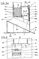
- Figures 2,3a,3b,3c show the dispensing apparatus 100 described heretofore as it is set for dispensing items 7 having box-like shape, particularly for dispensing an item each time.
- Figures 5 and 6 instead show the dispensing apparatus 100 when it is transformed to a money changer, that is done by a simple modification of the store compartment 10 shape, of the weight 18 and of the pusher 13.
- chute may be modified although it would not be necessary for this transformation.
- the supporting base 11 does not extend for the whole length of the items projection area, so that the items may be withdrawn with a stroke of the pusher 13 shorter than the length of the items.
- the characterizing features of the improved dispensing apparatus subject of the present invention are well evident from what has been stated above.
- the dispensing apparatus ensure for a good working operation although it includes only a few constructive elements which are simple but reliable.
- the dispensing apparatus does not include electro-mechanical means and therefore it requires low production costs and offers a wide number of possible installations since it does not requires electric power supply.
- the subject dispensing apparatus because of its particular configuration, turns out to be very effective against robbery attemps aimed at gathering items illegally.
Landscapes
- Physics & Mathematics (AREA)
- General Physics & Mathematics (AREA)
- Vending Machines For Individual Products (AREA)
- Purses, Travelling Bags, Baskets, Or Suitcases (AREA)
- Control Of Vending Devices And Auxiliary Devices For Vending Devices (AREA)
Claims (5)
- Verbesserter Warenausgabeapparat, bestehend aus einem Gehäuse (1) zur Aufnahme einer mechanischen Münzannahmevorrichtung (2) mit einem ersten Schlitz (3) zum Einwurf einer Geld- oder Automatenmünze, einer ersten Drucktaste (5) zur Rückgabe nicht akzeptierter Geld- oder Automatenmünzen mittels Auswurf über einen zweiten Schlitz (4), der sich unterhalb des ersten befindet; einem Mechanismus (50) zur Entnahme und Ausgabe einer vorbestimmten Anzahl von Artikeln (7), wobei der genannte Entnahme- und Ausgabemechanismus ferner umfaßt:mindestens einen senkrechten Vorratsspeicher (10), in dem ein Stapel (17) der genannten Warenartikel (7) enthalten ist, der auf einer waagrechten Grundfläche (11) aufliegt;einen Schieber (13) zum Wegschieben einer vorbestimmten Anzahl der genannten Artikel (7) vom unteren Ende (17b) des genannten Stapels (17);eine Rutsche (30), die unterhalb des genannten Vorratsspeichers (10) verläuft und die genannte vorbestimmte Anzahl von Artikeln (7) befördert und zu einem von außen zugänglichen Sammelbereich (8) leitet;einen beweglichen Verschluß (14), der an dem genannten Gehäuse (1) befestigt ist und der von einer Federvorrichtung (15) abhängt, die den Verschluß (14) in einer ersten Stellung (A) hält, in der das Einwerfen einer Geld- oder Automatenmünze in den ersten Schlitz (3) der Münzannahmevorrichtung (2) möglich ist;ein Gewicht (18), das auf der Oberseite (17a) des Stapels (17) von Artikeln (7) aufliegt und einen Vorsprung (18a) aufweist, der so geformt ist, daß er den genannten Verschluß (14) in eine zweite Stellung (B) verschiebt und in dieser Stellung hält, so daß der Einwurf einer Geld- oder Automatenmünze in den ersten Schlitz (3) der genannten Münzannahmevorrichtung (2) verhindert wird, wenn der Stapel (17) im Vorratsspeicher (10) keine Artikel (7) mehr enthält bzw. eine vorbestimmte Höhe erreicht;der genannte Ausgabeapparat ist dadurch gekennzeichnet, daß er eine zweite Drucktaste (6) aufweist, die zur Betätigung der genannten Entnahmeund Ausgabevorrichtung (50) dient und daß der durch die zweite Drucktaste (6) betätigte Schieber in waagrechter Richtung beweglich ist, so daß er durch eine entsprechend bemessene Öffnung (10a) in den genannten Vorratsspeicher (10) eingeführt werden kann; und daß ferner die erste Stellung des Verschlusses eine obere Position (A) und die zweite Stellung des Verschlusses eine untere Position (B) ist.
- Ausgabeapparat nach Anspruch 1, dadurch gekennzeichnet, daß der genannte Schieber (13) so ausgeführt ist, daß er den Stapel (17) trägt, während die vorbestimmte Anzahl von Artikeln (7) vom unteren Ende des Stapels (17) entnommen wird.
- Ausgabeapparat nach Anspruch 1, dadurch gekennzeichnet, daß der genannte Verschluß (14) zwei darin integrierte farbige Abschnitte (140a, 140b) aufweist, die beide von außen über ein im Gehäuse ausgespartes Fenster (16) sichtbar sind, und zwar jeweils eine davon, wenn sich der Verschluß (14) in seiner oberen Stellung (A) bzw. in seiner unteren Stellung (B) befindet.
- Ausgabeapparat nach Anspruch 1, dadurch gekennzeichnet, daß der genannte Schieber (13) einen fest damit verbundenen Arm (70) aufweist, der außerhalb des genannten Vorratsspeichers (10) und parallel zur Gleitrichtung des Schiebers angeordnet ist und einen Queranschlag (130) trägt, der so geformt ist, daß er die ungehinderte Entnahme der vorbestimmten Anzahl von Artikeln vom unteren Ende (17b) des Stapels (17) während der Vorwärtsbewegung des Schiebers (13) ermöglicht und gleichzeitig jeglichen Zugang zu den an der unteren Öffnung des Vorratsspeichers liegenden Artikeln verhindert.
- Ausgabeapparat nach Anspruch 4, dadurch gekennzeichnet, daß der genannte Queranschlag (130) einen Flansch aufweist, der sich zu dem genannten Stapel (17) hin erstreckt und dazu dient, die genannten Artikel (7) zu stützen, wenn nur noch wenige davon im Stapel vorhanden sind.
Applications Claiming Priority (2)
| Application Number | Priority Date | Filing Date | Title |
|---|---|---|---|
| ITBO920278A IT1257860B (it) | 1992-07-16 | 1992-07-16 | Distributore perfezionato di articoli |
| ITBO920278 | 1992-07-16 |
Publications (2)
| Publication Number | Publication Date |
|---|---|
| EP0583225A1 EP0583225A1 (de) | 1994-02-16 |
| EP0583225B1 true EP0583225B1 (de) | 1996-11-20 |
Family
ID=11338422
Family Applications (1)
| Application Number | Title | Priority Date | Filing Date |
|---|---|---|---|
| EP93830294A Expired - Lifetime EP0583225B1 (de) | 1992-07-16 | 1993-07-06 | Verbesserte Vorrichtung zum Ausgeben von Warenstücken |
Country Status (4)
| Country | Link |
|---|---|
| EP (1) | EP0583225B1 (de) |
| DE (1) | DE69306058T2 (de) |
| ES (1) | ES2094515T3 (de) |
| IT (1) | IT1257860B (de) |
Families Citing this family (1)
| Publication number | Priority date | Publication date | Assignee | Title |
|---|---|---|---|---|
| DE102009014316B4 (de) * | 2009-03-25 | 2019-03-14 | Sew-Eurodrive Gmbh & Co Kg | Getriebe |
Family Cites Families (5)
| Publication number | Priority date | Publication date | Assignee | Title |
|---|---|---|---|---|
| US1778187A (en) * | 1926-04-26 | 1930-10-14 | Cons Automatic Merchandising C | Vending machine |
| US1686949A (en) * | 1927-06-04 | 1928-10-09 | Hollweck & Bauer | Indicating means for vending machines |
| GB368848A (en) * | 1930-12-12 | 1932-03-14 | F S Automatics Ltd | Improvements in or relating to coin-freed vending-machines |
| GB480636A (en) * | 1936-05-04 | 1938-02-25 | Seitz Werke Gmbh | Improvements in or relating to coin-freed vending machines |
| GB912801A (en) * | 1957-10-14 | 1962-12-12 | Fisher & Ludlow Ltd | Improvements in or relating to coin freed mechanism |
-
1992
- 1992-07-16 IT ITBO920278A patent/IT1257860B/it active IP Right Grant
-
1993
- 1993-07-06 DE DE69306058T patent/DE69306058T2/de not_active Expired - Fee Related
- 1993-07-06 EP EP93830294A patent/EP0583225B1/de not_active Expired - Lifetime
- 1993-07-06 ES ES93830294T patent/ES2094515T3/es not_active Expired - Lifetime
Also Published As
| Publication number | Publication date |
|---|---|
| ES2094515T3 (es) | 1997-01-16 |
| DE69306058T2 (de) | 1997-03-13 |
| ITBO920278A1 (it) | 1994-01-16 |
| IT1257860B (it) | 1996-02-13 |
| DE69306058D1 (de) | 1997-01-02 |
| EP0583225A1 (de) | 1994-02-16 |
| ITBO920278A0 (it) | 1992-07-16 |
Similar Documents
| Publication | Publication Date | Title |
|---|---|---|
| US2893596A (en) | Sandwich merchandising machine | |
| US3938700A (en) | Multi-rack article dispensing apparatus | |
| US3194432A (en) | Vending machine | |
| KR102222237B1 (ko) | 다종카드 디스펜서 | |
| US5492212A (en) | Device for sorting and storing objects inserted by way of payment in a dispenser | |
| US4494675A (en) | Article dispensing machine with anti-theft structure | |
| US2435526A (en) | Multiple compartment vending machine | |
| US5137134A (en) | Vending machine for newspapers and magazines | |
| US2847146A (en) | Vending machines for packaged merchandise or the like | |
| US3904076A (en) | Adaptable dispensing apparatus with unique escrow bar and associated latch mechanism | |
| US3734344A (en) | Coin operated article vending machine | |
| US7077288B2 (en) | Newspaper vending machine | |
| US2989165A (en) | Vending machine | |
| EP0583225A1 (de) | Verbesserte Vorrichtung zum Ausgeben von Warenstücken | |
| US1505725A (en) | Vending machine | |
| US1600158A (en) | Vending machine | |
| GB2224498A (en) | Mechanism for dispensing article from stack | |
| US2180326A (en) | Vending machine | |
| US3184105A (en) | Record vending machine | |
| US2996218A (en) | Vending machines | |
| US2949210A (en) | Coin controlled game apparatus | |
| US1648813A (en) | Vending machine | |
| EP4280183A1 (de) | Verkaufsautomat zur ausgabe von verpackten produkten und verfahren zur ausgabe eines verpackten produkts aus einem verkaufsautomat | |
| WO2005109355A2 (en) | Vending machine for articles | |
| US1947322A (en) | Vending machine |
Legal Events
| Date | Code | Title | Description |
|---|---|---|---|
| PUAI | Public reference made under article 153(3) epc to a published international application that has entered the european phase |
Free format text: ORIGINAL CODE: 0009012 |
|
| AK | Designated contracting states |
Kind code of ref document: A1 Designated state(s): DE ES FR GB IE IT |
|
| 17P | Request for examination filed |
Effective date: 19940805 |
|
| 17Q | First examination report despatched |
Effective date: 19950913 |
|
| GRAG | Despatch of communication of intention to grant |
Free format text: ORIGINAL CODE: EPIDOS AGRA |
|
| GRAH | Despatch of communication of intention to grant a patent |
Free format text: ORIGINAL CODE: EPIDOS IGRA |
|
| GRAH | Despatch of communication of intention to grant a patent |
Free format text: ORIGINAL CODE: EPIDOS IGRA |
|
| ITF | It: translation for a ep patent filed | ||
| GRAA | (expected) grant |
Free format text: ORIGINAL CODE: 0009210 |
|
| AK | Designated contracting states |
Kind code of ref document: B1 Designated state(s): DE ES FR GB IE IT |
|
| REG | Reference to a national code |
Ref country code: IE Ref legal event code: FG4D Free format text: 70688 |
|
| REF | Corresponds to: |
Ref document number: 69306058 Country of ref document: DE Date of ref document: 19970102 |
|
| REG | Reference to a national code |
Ref country code: ES Ref legal event code: FG2A Ref document number: 2094515 Country of ref document: ES Kind code of ref document: T3 |
|
| ET | Fr: translation filed | ||
| PG25 | Lapsed in a contracting state [announced via postgrant information from national office to epo] |
Ref country code: IE Free format text: LAPSE BECAUSE OF NON-PAYMENT OF DUE FEES Effective date: 19970706 |
|
| PLBE | No opposition filed within time limit |
Free format text: ORIGINAL CODE: 0009261 |
|
| STAA | Information on the status of an ep patent application or granted ep patent |
Free format text: STATUS: NO OPPOSITION FILED WITHIN TIME LIMIT |
|
| 26N | No opposition filed | ||
| PG25 | Lapsed in a contracting state [announced via postgrant information from national office to epo] |
Ref country code: DE Free format text: LAPSE BECAUSE OF NON-PAYMENT OF DUE FEES Effective date: 19980401 |
|
| PGFP | Annual fee paid to national office [announced via postgrant information from national office to epo] |
Ref country code: GB Payment date: 19990630 Year of fee payment: 7 |
|
| PG25 | Lapsed in a contracting state [announced via postgrant information from national office to epo] |
Ref country code: GB Free format text: LAPSE BECAUSE OF NON-PAYMENT OF DUE FEES Effective date: 20000706 |
|
| PGFP | Annual fee paid to national office [announced via postgrant information from national office to epo] |
Ref country code: ES Payment date: 20000712 Year of fee payment: 8 |
|
| GBPC | Gb: european patent ceased through non-payment of renewal fee |
Effective date: 20000706 |
|
| PGFP | Annual fee paid to national office [announced via postgrant information from national office to epo] |
Ref country code: FR Payment date: 20010628 Year of fee payment: 9 |
|
| PG25 | Lapsed in a contracting state [announced via postgrant information from national office to epo] |
Ref country code: ES Free format text: LAPSE BECAUSE OF NON-PAYMENT OF DUE FEES Effective date: 20010707 |
|
| PG25 | Lapsed in a contracting state [announced via postgrant information from national office to epo] |
Ref country code: FR Free format text: LAPSE BECAUSE OF NON-PAYMENT OF DUE FEES Effective date: 20030331 |
|
| REG | Reference to a national code |
Ref country code: FR Ref legal event code: ST |
|
| REG | Reference to a national code |
Ref country code: ES Ref legal event code: FD2A Effective date: 20020810 |
|
| PG25 | Lapsed in a contracting state [announced via postgrant information from national office to epo] |
Ref country code: IT Free format text: LAPSE BECAUSE OF NON-PAYMENT OF DUE FEES;WARNING: LAPSES OF ITALIAN PATENTS WITH EFFECTIVE DATE BEFORE 2007 MAY HAVE OCCURRED AT ANY TIME BEFORE 2007. THE CORRECT EFFECTIVE DATE MAY BE DIFFERENT FROM THE ONE RECORDED. Effective date: 20050706 |