EP0583246B1 - Appareil et procede pour mesurer et retablir le potentiel electrique d'une electrode - Google Patents
Appareil et procede pour mesurer et retablir le potentiel electrique d'une electrode Download PDFInfo
- Publication number
- EP0583246B1 EP0583246B1 EP92905209A EP92905209A EP0583246B1 EP 0583246 B1 EP0583246 B1 EP 0583246B1 EP 92905209 A EP92905209 A EP 92905209A EP 92905209 A EP92905209 A EP 92905209A EP 0583246 B1 EP0583246 B1 EP 0583246B1
- Authority
- EP
- European Patent Office
- Prior art keywords
- electrode
- electrical potential
- potential
- restoring
- intervals
- Prior art date
- Legal status (The legal status is an assumption and is not a legal conclusion. Google has not performed a legal analysis and makes no representation as to the accuracy of the status listed.)
- Expired - Lifetime
Links
Images

Classifications
-
- A—HUMAN NECESSITIES
- A61—MEDICAL OR VETERINARY SCIENCE; HYGIENE
- A61N—ELECTROTHERAPY; MAGNETOTHERAPY; RADIATION THERAPY; ULTRASOUND THERAPY
- A61N1/00—Electrotherapy; Circuits therefor
- A61N1/18—Applying electric currents by contact electrodes
- A61N1/32—Applying electric currents by contact electrodes alternating or intermittent currents
- A61N1/36—Applying electric currents by contact electrodes alternating or intermittent currents for stimulation
- A61N1/362—Heart stimulators
- A61N1/365—Heart stimulators controlled by a physiological parameter, e.g. heart potential
Definitions
- My invention relates to implantable therapeutic devices having electrodes carried on leads, and in particular to implantable cardiac pacemakers. More specifically, my invention relates to a cardiac pacemaker having an electrode on an implanted lead adapted to perform multiple functions through the same electrode; for example, the function of pacing the heart and the function of measuring a parameter indicative of the physiologic condition of the patient or the patient's heart.
- Electrodes have been used to measure electric signals relating to chemical concentrations, nerve activity, respiration rate, or cardiac rhythms, as examples.
- Cardiac pacemakers for example, stimulate the heart with electrical impulses to induce a heartbeat. Pacemakers may also sense the condition of the heart so that stimuli may be applied in an appropriate manner.
- Electrodes on a lead of a cardiac pacemaker may be used to measure features of the intracardiac electrogram, lead or tissue impedance, pH of the blood and other parameters.
- the electrode may detect unwanted signals such as remote or far field signals, noise, muscle activity potentials and so on.
- the sense electrode or another electrode may be used to stimulate a physiological mechanism by an appropriate signal; for example, stimulating the heart to induce a heartbeat. Such a stimulation can result in a residual polarization voltage which masks the desired signal.
- Accurate signal detection through an implanted electrode continues to present difficulties for the designer of an implanted therapeutic device.
- it may be desired to detect one or more input signals and to apply one or more stimulating or output signals.
- it may be inadvisable to employ a dedicated electrode for each operation.
- the desired size of a lead may limit the number of conducting wires which can practically be connected to separate electrodes or the number of electrodes themselves may be limited.
- interelectrode cross-talk between separate electrodes may limit the usefulness of separate electrodes.
- time multiplexing of an electrode has heretofore been employed.
- the same electrode used to output a stimulating pulse during a first interval may be employed to sense cardiac signals during another interval and noise or some other parameter during yet another interval.
- Bandpass filtering has been used to discriminate between desirable signals and noise.
- EP-A-0 246 908 discloses an apparatus for measuring an electrical potential at an electrode, and discloses a technique for reducing the charge accumulated as a result of a stimulation pulse being delivered by the electrode, which involves sampling and holding of the electrical potential immediately after the stimulation pulse, at the beginning of a sensing interval, and subsequent restoration of ground potential at the electrode.
- WO-A-8 909 514 and EP-A-0 043 690 relate to apparatus for suppressing artifacts produced by a stimulating device from the signal detected by an ECG device.
- the stimulating and ECG devices use different, spatially spaced electrodes, and no potential restoration at an electrode is performed.
- Another object of my invention is to provide an implanted apparatus which can extract information from a background signal during a selected interval despite the presence of a primary signal which tends, during another time interval, to influence the electrode potential to destroy the electrode's ability to sense the background signal.
- an intervening event may occur to seriously disrupt the potential.
- This intervening event may be either an intrinsic potential caused by the human body or an external stimulation; for example, a stimulus from a pacemaker. If such an intervening event occurred during the second time interval, the stored value of the measured potential will be restored as an initial value at the end of the second interval.
- Apparatus includes a timing circuit to identify appropriate intervals.
- Control circuitry or software is provided to determine if conditions have occurred which require potential restoration.
- Means are provided for sampling and storing the value of the electric potential at a given time and for restoring the measured potential to an electrode at a second selected time.
- the means may include electrical circuitry or software and may employ either analog circuitry or analog to digital conversion with digital registers or memory circuitry. Algorithms to establish appropriate responses to detected noise or other classes of signals may also be provided.
- My invention may be employed with electrodes generally, including physiological, chemical, physical, or other electrodes. It may also be used to set the initial potential conditions of one electrode with reference to a detected condition at another electrode.
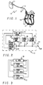
- FIG. 1 is perspective view of a cardiac pacemaker system according to my present invention with a cardiac pacemaker and a lead, showing placement of the lead in a cutaway section of a human heart.
- FIG. 2 is a block diagram of a heart pacemaker employing apparatus according to my invention.
- FIG. 3 is a logic diagram for describing timing of switches according to my present invention.
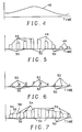
- FIG. 4 is a graph of a potential varying over time.
- FIG. 5 is the potential of FIG. 4 sampled at selected intervals.
- FIG. 6 is a graph of a sampling of the potential of FIG. 4 with the potential forced to zero at the beginning of each interval.
- FIG. 7 is a sampling of the potential of FIG. 4 with the terminal conditions of each sampled interval imposed on the succeeding sample interval as initial conditions.
- FIG. 8 is a graph of an electric potential comprising a potential similar to that shown in FIG. 4 combined with an intrinsic cardiac depolarization signal.
- FIG. 9 is a graph of the potential of FIG. 8 combined with stimulating cardiac pacing pulses.
- FIG. 10 is a potential including the potential of FIG. 9 combined with restoration of initial conditions according to my present invention.
- FIG. 11 is the potential of FIG. 10 with the cardiac pulses and stimulating pulses eliminated.
- FIG. 1 a perspective view of a cardiac pacemaker system , generally designated 10, is shown in perspective view.
- a cardiac pacemaker 12 is provided having the capacity to sense electrical artifacts at sense electrodes within a heart.
- a lead 14 is shown connected to the pacemaker 12.
- the lead is illustrated as having a distal electrode 16 at a distal end of the lead.
- fixation means should generally be provided.
- the distal electrode 16 may be used for both sensing and stimulating the heart in accordance with my present invention.
- An additional ring electrode 18 is shown within the atrium of the heart. The ring electrode 18 may also be used for multiple purposes and employed with the apparatus of my present invention. It will be apparent that the number of electrodes employing the invention is not limited.
- FIG. 2 illustrates a block diagram of the cardiac pacemaker 12 showing the apparatus of my present invention.
- the lead 14 and the distal tip 16 are illustrated. Additional connections may be provided for additional electrodes, such as electrode 18.
- Timing and control circuitry 22 control pacing output circuitry 24 to provide stimulating pulses to the heart and, at appropriate times, receive signals from sensing input circuitry 26 from the heart. Multiplexing between pacing and sensing are known in the pacemaker art and need not be described in greater detail herein.
- Sensed signals may comprise the heart's QRS complexes, polarization potentials on the electrode 16, noise from electromagnetic sources or from muscles of the body, or various physiological parameters such as respiration, pH and so on.
- Timing and control circuitry 22 may be implemented by those skilled in the art in either electrical hardware or a combination of hardware and software.
- a first switch 28 closes briefly after an output pulse is delivered from the pacing output 24. Closing of the first switch 28 connects the electrode 16 to ground or charge dump 29.
- the timing and control circuitry 22 may then begin to time out a physiological parameter sampling interval for a predetermined length of time. At the beginning of the sampling interval, the timing and controlling circuit closes a restore switch 30 which connects a charge restore circuit 32 to the electrode 16.
- the charge restore circuit 32 is effective to restore the electrical condition of the electrode to the condition of that electrode at the end of the last preceding sampling interval.
- the charge control circuit 32 may be implemented by a storage capacitor and analog circuitry or by digital circuitry with a digital to analog converter.
- the timing and control circuitry 32 then activates the sensing input 26 to measure the desired electrical potential at the electrode 16 during the sampling interval.
- the timing and control circuit 22 briefly closes a charge store switch 34 and stores the value of the potential of the electrode 16 in charge store means 36.
- the charge store means may comprise analog or digital circuitry. Any anticipated losses to the electrode potential occurring in either potential measurement, charge storage or restoration are compensated in transferring the charge storage means 36 to the charge restore means 32.
- Control of the switches 28, 30 and 34 can also be understood with reference to the logic diagram of FIG. 3. Under the control of the timing in control circuit 22, all switches are normally open 38. Before attempting to restore the electrical condition of the electrode 16, as, for example, after a stimulating pulse from the pacing output 24, first switch 28 closes 40, connecting the electrode to ground and then quickly reopens. Just before the sampling interval and after switch 28 has been closed, the charge restore switch 30 closes 42, allowing charge restore circuitry 32 to charge the electrode 16 to the predetermined electrical condition. The electrical condition of the electrode is relatively quickly restored and then switch 30 again reopens. Just before the end of the sampling interval, the charge store switch 34 is closed 44 connecting the charge store means 36 to the electrode. The electrical condition of the electrode is rapidly sampled over a very short interval and the switch 34 is again opened.
- FIG. 4 illustrates an exemplary electrical potential 46 which varies in amplitude over time.
- the electrical potential is the signal which is to be measured or detected by an electrode. This does not imply, however, that the potential 46 is the only electrical signal present. There may be other signals, extraneous noise, or, in the case of a heart pacemaker, output signals or stimulating pulses which mask or make the measurement of the potential 46 more difficult.
- FIG. 5 shows an idealized measurement of the potential 46 by a multiplexed electrode.
- the electrode 16 is multiplexed to its sensing function, potential segments 48 are sensed during selected intervals 50.
- the potential segments 48 closely approximate the potential 46 and meaningful information about the potential 46 can be extracted from the potential segments 48.
- the wave form of FIG. 5 is seldom if ever retrieved. This is because the initial conditions of the segments 48 in reality do not correspond to the initial conditions of each segment as shown in FIG. 5. Rather, each segment begins at some other value and only approaches the true value for the segment. Such a condition is illustrated in FIG. 6. At the beginning of each time segment 50 the value of the measured potential is constrained to be zero.
- Such a condition might occur if the electrode were grounded immediately before the beginning of the time segment 50.
- the zero initial condition is chosen only as an example because of its simplicity and clarity. Any other initial condition, constant or varying, which was not related to the desired signal 46, would have the same negative affect. Because of the inherent time constants of the system, during each measurement 50 a measured segment of potential 52 will only begin to approximate the true value of the potential 46. A great deal of information about the potential 46 could be lost, resulting in potentially erroneous responses by an implanted device such as a cardiac pacemaker.
- the wave form of FIG. 7 would be recovered.
- the magnitude of the measured potential would more closely approximate the true potential 46.
- the magnitude or other parameter of the potential would be stored.
- the ending value at 56 would be restored to the electrode. Measurement would then begin and the potential on the electrode would begin to approach the true value of the potential 46, constrained by the inherent time constants of the particular system. Since it is likely, however, that the value at the end of the last measuring period more closely approximates the true value at the beginning of the next succeeding period than would an arbitrary value such as zero, the measurement of potential, as shown in FIG. 7, would more closely approximate the idealized measurements of FIG. 5 and thus be a better representation of the true potential shown in FIG. 4.
- FIGS. 8 through 11 illustrate an application of my invention in the field of cardiac pacing.
- FIG. 8 shows a signal 60 similar to the potential 46 of FIG. 4 but with the addition of an intrinsic intracardiac QRS complex 62 at periodic intervals. Such a signal 62 would be detected on an electrode in the right ventricle of a typical healthy heart.
- the intrinsic QRS signals 62 are essentially added to the underlying baseline potential 46 shown in FIG. 4. To extract the baseline potential a low pass filter or sampling method analogous to that illustrated in FIG. 5 might be employed. Under such circumstances filtering and sampling would be adequate to extract the desired information.
- FIG. 9 illustrates the result of cardiac pacing on a prior art bandpass and sampling electrode.
- a pacing pulse 64 and resulting depolarization disrupts the measurement of the signal 60.
- Charge dumping a known technique used to reduce lead polarization potential, tends to force the voltage at the electrode to zero after each pulse.
- the sampling of the underlying baseline potential occurs during the intervals between pulses. Because of the pacing, the sampling intervals 50 may tend to occur irregularly over time, being associated with a delay after the pacing pulse.
- charge dumping removes the baseline information and distorts the sample values. Over time, of course, the baseline will return to its natural value but during the time period surrounding a series of pacer pulses, significant amounts of information will be lost.
- FIG. 11 extracts an approximation 61 of the baseline information from FIG. 10 and omits the pacer pulses and intrinsic QRS waves. A comparison between this waveform and the waveform of FIG. 8 or FIG. 4 illustrates that a closer approximation of the baseline potential can be expected.
Landscapes
- Health & Medical Sciences (AREA)
- Heart & Thoracic Surgery (AREA)
- Life Sciences & Earth Sciences (AREA)
- Cardiology (AREA)
- Nuclear Medicine, Radiotherapy & Molecular Imaging (AREA)
- Physiology (AREA)
- Engineering & Computer Science (AREA)
- Biomedical Technology (AREA)
- Biophysics (AREA)
- Radiology & Medical Imaging (AREA)
- Animal Behavior & Ethology (AREA)
- General Health & Medical Sciences (AREA)
- Public Health (AREA)
- Veterinary Medicine (AREA)
- Electrotherapy Devices (AREA)
- Measurement Of Current Or Voltage (AREA)
Abstract
Claims (16)
- Appareil de mesure d'un potentiel électrique, comprenant :une électrode (16) destinée à l'échantillonnage du potentiel électrique,un dispositif (22) de minutage d'une série de premiers et seconds intervalles,un dispositif (26) de mesure du potentiel électrique au niveau de l'électrode pendant les premiers intervalles,un dispositif (36) de mémorisation de la valeur du potentiel électrique mesuré à la fin des premiers intervalles, etun dispositif (32) de rétablissement du potentiel électrique à l'électrode à la fin des seconds intervalles à la valeur mémorisée du potentiel électrique mesure.
- Appareil selon la revendication 1, comprenant en outre un dispositif de compensation des pertes prévues lors du rétablissement de la valeur mémorisée du potentiel électrique.
- Appareil selon la revendication 2, comprenant en outre un dispositif (29) de connexion de l'électrode à la masse avant le rétablissement de la valeur mémorisée du potentiel électrique.
- Appareil selon la revendication 3, dans lequel le dispositif de mémorisation, le dispositif de rétablissement et le dispositif de connexion à la masse comportent chacun un dispositif de commutation (34, 30, 28) destiné à connecter et déconnecter sélectivement le dispositif respectif à l'électrode, et le dispositif de minutage comporte en outre un dispositif destiné à commander les commutateurs.
- Appareil selon la revendication 4, dans lequel les commutateurs sont normalement ouverts pour la déconnexion du dispositif de mémorisation, du dispositif de rétablissement et du dispositif de connexion à la masse de l'électrode, sauf lorsque le dispositif respectif est en fonctionnement.
- Appareil selon la revendication 5, comprenant en outre un dispositif (24) destiné à transmettre un signal électrique de sortie par l'électrode pendant certains au moins des seconds intervalles.
- Appareil selon la revendication 1, incorporé à un stimulateur cardiaque (12) pour la mesure d'un potentiel électrique dans le coeur, le stimulateur comprenant un dispositif commandé par l'appareil et destiné à stimuler le coeur en fonction du potentiel électrique.
- Stimulateur cardiaque selon la revendication 7, comprenant en outre un dispositif de compensation des pertes prévues lors du rétablissement de la valeur mémorisée du potentiel électrique.
- Stimulateur cardiaque selon la revendication 8, comprenant en outre un dispositif (29) de connexion du dispositif de détection à la masse avant le rétablissement de la valeur mémorisée du potentiel électrique.
- Stimulateur cardiaque selon la revendication 9, dans lequel le dispositif de mémorisation, le dispositif de rétablissement et le dispositif de connexion à la masse comportent chacun un commutateur (34, 30, 28) destiné à connecter le dispositif respectif à l'électrode portée sur un fil et à le déconnecter sélectivement, et le dispositif de minutage comporte en outre un dispositif de commande des commutateurs.
- Stimulateur cardiaque selon la revendication 10, dans lequel les commutateurs sont d'un type normalement ouvert et déconnectent ainsi le dispositif de mémorisation, le dispositif de rétablissement et le dispositif de connexion à la masse de l'électrode sauf lorsque le dispositif respectif est en fonctionnement.
- Stimulateur cardiaque selon la revendication 11, dans lequel le dispositif de simulation comporte en outre un dispositif (24) destiné à transmettre un signal électrique de sortie par l'électrode pendant certains au moins des seconds intervalles.
- Procédé de mesure d'un potentiel électrique à une électrode d'échantillonnage (16), comprenant :l'échantillonnage du potentiel électrique,le minutage d'une série de premiers et de seconds intervalles,la mesure du potentiel électrique pendant les premiers intervalles,la mémorisation de la valeur du potentiel électrique à la fin des premiers intervalles, etle rétablissement du potentiel électrique à la valeur mémorisée du potentiel électrique à la fin des seconds intervalles.
- Procédé selon la revendication 13, comprenant en outre la compensation des pertes prévues lors du rétablissement de la valeur mémorisée du potentiel électrique.
- Procédé selon la revendication 14, comprenant en outre la connexion de l'électrode d'échantillonnage à la masse avant le rétablissement de la valeur mémorisée du potentiel électrique.
- Procédé selon la revendication 15, comprenant en outre la connexion à l'électrode et la déconnexion sélective du dispositif de mémorisation, du dispositif de rétablissement et du dispositif de connexion à la masse.
Applications Claiming Priority (3)
| Application Number | Priority Date | Filing Date | Title |
|---|---|---|---|
| US07/696,160 US5228437A (en) | 1991-05-06 | 1991-05-06 | Cardiac pacemaker and method for detecting cardiac signals |
| PCT/US1992/000502 WO1992019319A1 (fr) | 1991-05-06 | 1992-01-21 | Appareil et procede pour stimulateur cardiaque implante a electrode a multi-usage et retablissement de potentiel |
| US696160 | 2000-10-23 |
Publications (2)
| Publication Number | Publication Date |
|---|---|
| EP0583246A1 EP0583246A1 (fr) | 1994-02-23 |
| EP0583246B1 true EP0583246B1 (fr) | 1997-03-05 |
Family
ID=24795957
Family Applications (1)
| Application Number | Title | Priority Date | Filing Date |
|---|---|---|---|
| EP92905209A Expired - Lifetime EP0583246B1 (fr) | 1991-05-06 | 1992-01-21 | Appareil et procede pour mesurer et retablir le potentiel electrique d'une electrode |
Country Status (6)
| Country | Link |
|---|---|
| US (1) | US5228437A (fr) |
| EP (1) | EP0583246B1 (fr) |
| JP (1) | JPH06506840A (fr) |
| DE (1) | DE69217932T2 (fr) |
| ES (1) | ES2101087T3 (fr) |
| WO (1) | WO1992019319A1 (fr) |
Families Citing this family (5)
| Publication number | Priority date | Publication date | Assignee | Title |
|---|---|---|---|---|
| US5658316A (en) * | 1995-07-03 | 1997-08-19 | Automatic Defibrillator, Inc. | Portable defibrillator with disposable power pack |
| SE9600511D0 (sv) * | 1996-02-12 | 1996-02-12 | Pacesetter Ab | Bipolar sensor electrode |
| US7536224B2 (en) * | 2003-04-30 | 2009-05-19 | Medtronic, Inc. | Method for elimination of ventricular pro-arrhythmic effect caused by atrial therapy |
| CN107206242B (zh) | 2015-02-06 | 2020-10-30 | 心脏起搏器股份公司 | 用于电刺激治疗的安全递送的系统和方法 |
| EP3684465B1 (fr) | 2017-09-20 | 2021-07-14 | Cardiac Pacemakers, Inc. | Dispositif médical implantable avec modes de fonctionnement multiples |
Family Cites Families (12)
| Publication number | Priority date | Publication date | Assignee | Title |
|---|---|---|---|---|
| US4114627A (en) * | 1976-12-14 | 1978-09-19 | American Hospital Supply Corporation | Cardiac pacer system and method with capture verification signal |
| US4343312A (en) * | 1979-04-16 | 1982-08-10 | Vitafin N.V. | Pacemaker output circuit |
| US4331157A (en) * | 1980-07-09 | 1982-05-25 | Stimtech, Inc. | Mutually noninterfering transcutaneous nerve stimulation and patient monitoring |
| DE3260610D1 (en) * | 1981-02-05 | 1984-10-04 | Vitafin Nv | Apparatus and method for physiological stimulation and detection of evoked response |
| US4399818A (en) * | 1981-04-06 | 1983-08-23 | Telectronics Pty. Ltd. | Direct-coupled output stage for rapid-signal biological stimulator |
| US4498478A (en) * | 1982-09-13 | 1985-02-12 | Medtronic, Inc. | Apparatus for reducing polarization potentials in a pacemaker |
| US4540000A (en) * | 1983-12-15 | 1985-09-10 | Ocg Technology Inc. | Signal conditioner for biological signals |
| US4759366A (en) * | 1986-03-19 | 1988-07-26 | Telectronics N.V. | Rate responsive pacing using the ventricular gradient |
| GB8612659D0 (en) * | 1986-05-23 | 1986-07-02 | Coventry City Council | Cardiac pacemaker circuit |
| US4821724A (en) * | 1986-08-01 | 1989-04-18 | Telectronics N.V. | Pacing pulse compensation |
| WO1989009514A1 (fr) * | 1988-03-25 | 1989-10-05 | Arzco Medical Electronics | Procede et appareil de suppression d'artefacts |
| US5065351A (en) * | 1989-03-30 | 1991-11-12 | Eastman Kodak Company | Stabilization and calibration of precision electronic circuit component |
-
1991
- 1991-05-06 US US07/696,160 patent/US5228437A/en not_active Expired - Lifetime
-
1992
- 1992-01-21 JP JP4505407A patent/JPH06506840A/ja active Pending
- 1992-01-21 ES ES92905209T patent/ES2101087T3/es not_active Expired - Lifetime
- 1992-01-21 WO PCT/US1992/000502 patent/WO1992019319A1/fr not_active Ceased
- 1992-01-21 EP EP92905209A patent/EP0583246B1/fr not_active Expired - Lifetime
- 1992-01-21 DE DE69217932T patent/DE69217932T2/de not_active Expired - Fee Related
Also Published As
| Publication number | Publication date |
|---|---|
| ES2101087T3 (es) | 1997-07-01 |
| US5228437A (en) | 1993-07-20 |
| DE69217932T2 (de) | 1997-10-02 |
| DE69217932D1 (de) | 1997-04-10 |
| WO1992019319A1 (fr) | 1992-11-12 |
| EP0583246A1 (fr) | 1994-02-23 |
| JPH06506840A (ja) | 1994-08-04 |
Similar Documents
| Publication | Publication Date | Title |
|---|---|---|
| US6134473A (en) | Microprocessor capture detection circuit and method | |
| US6163724A (en) | Microprocessor capture detection circuit and method | |
| US5861013A (en) | Peak tracking capture detection circuit and method | |
| EP0596319B1 (fr) | Appareil de stimulation cardiaque | |
| US7792584B2 (en) | System and method for characterization of atrial wall using digital signal processing | |
| US6275734B1 (en) | Efficient generation of sensing signals in an implantable medical device such as a pacemaker or ICD | |
| US5507785A (en) | Rate responsive cardiac pacemaker with biphasic impedance sensing and method | |
| US6230059B1 (en) | Implantable monitor | |
| US5018523A (en) | Apparatus for common mode stimulation with bipolar sensing | |
| Haddad et al. | The evolution of pacemakers | |
| US5782884A (en) | Rate responsive cardiac pacemaker with peak impedance detection for rate control | |
| EP1427473B1 (fr) | Gabarits multiples de filtrage des ondes r de champ eloigne | |
| US5431692A (en) | Method and apparatus for testing compatibility of lead polarity and polarity programming of a cardiac stimulator | |
| US6363281B1 (en) | Cardiac rhythm management system and method | |
| US5954756A (en) | Microprocessor capture detection circuit and method | |
| EP0341297A1 (fr) | Detecteurs de marge de detection pour des dispositifs electromedicaux implantables | |
| WO1998025671A1 (fr) | Stimulateur cardiaque implantable avec seuil automatique base sur l'impedance | |
| EP0594627A1 (fr) | Stimulateur medical utilisant le circuit de sortie de l'amplificateur operationnel. | |
| EP0583246B1 (fr) | Appareil et procede pour mesurer et retablir le potentiel electrique d'une electrode | |
| Sandler et al. | Inappropriate discharge by an implantable cardioverter defibrillator: recognition of myopotential sensing using telemetered intracardiac electrograms | |
| US7203544B2 (en) | Detection of evoked post-stimulation potentials, in particular atrial potentials in an active implantable medical device such as cardiac pacemaker, defribillator, cardiovertor or multisite device | |
| Exner et al. | Unipolar sensing in contemporary pacemakers: using myopotential testing to define optimal sensitivity settings | |
| Zhu et al. | Effect of pacemaker output coupling capacitor on intracardiac evoked response sensing | |
| OHM | Inhibition/Filter Characteristics and Input Impedances of QRS‐Inhibited Demand Pacemakers Determined by in vitro Studies | |
| Haddad et al. | The evolution of pacemakers: an electronics perspective, from the hand crank to advanced wavelet analysis |
Legal Events
| Date | Code | Title | Description |
|---|---|---|---|
| PUAI | Public reference made under article 153(3) epc to a published international application that has entered the european phase |
Free format text: ORIGINAL CODE: 0009012 |
|
| 17P | Request for examination filed |
Effective date: 19931130 |
|
| AK | Designated contracting states |
Kind code of ref document: A1 Designated state(s): DE ES FR GB IT NL SE |
|
| 17Q | First examination report despatched |
Effective date: 19950612 |
|
| GRAG | Despatch of communication of intention to grant |
Free format text: ORIGINAL CODE: EPIDOS AGRA |
|
| GRAH | Despatch of communication of intention to grant a patent |
Free format text: ORIGINAL CODE: EPIDOS IGRA |
|
| GRAH | Despatch of communication of intention to grant a patent |
Free format text: ORIGINAL CODE: EPIDOS IGRA |
|
| GRAA | (expected) grant |
Free format text: ORIGINAL CODE: 0009210 |
|
| AK | Designated contracting states |
Kind code of ref document: B1 Designated state(s): DE ES FR GB IT NL SE |
|
| ET | Fr: translation filed | ||
| REF | Corresponds to: |
Ref document number: 69217932 Country of ref document: DE Date of ref document: 19970410 |
|
| ET | Fr: translation filed |
Free format text: CORRECTIONS |
|
| ITF | It: translation for a ep patent filed | ||
| REG | Reference to a national code |
Ref country code: ES Ref legal event code: FG2A Ref document number: 2101087 Country of ref document: ES Kind code of ref document: T3 |
|
| PLBE | No opposition filed within time limit |
Free format text: ORIGINAL CODE: 0009261 |
|
| STAA | Information on the status of an ep patent application or granted ep patent |
Free format text: STATUS: NO OPPOSITION FILED WITHIN TIME LIMIT |
|
| 26N | No opposition filed | ||
| NLT1 | Nl: modifications of names registered in virtue of documents presented to the patent office pursuant to art. 16 a, paragraph 1 |
Owner name: SULZER INTERMEDICS INC. |
|
| PGFP | Annual fee paid to national office [announced via postgrant information from national office to epo] |
Ref country code: FR Payment date: 20010102 Year of fee payment: 10 |
|
| PGFP | Annual fee paid to national office [announced via postgrant information from national office to epo] |
Ref country code: DE Payment date: 20010103 Year of fee payment: 10 Ref country code: SE Payment date: 20010103 Year of fee payment: 10 |
|
| PGFP | Annual fee paid to national office [announced via postgrant information from national office to epo] |
Ref country code: GB Payment date: 20010105 Year of fee payment: 10 |
|
| PGFP | Annual fee paid to national office [announced via postgrant information from national office to epo] |
Ref country code: NL Payment date: 20010123 Year of fee payment: 10 |
|
| PGFP | Annual fee paid to national office [announced via postgrant information from national office to epo] |
Ref country code: ES Payment date: 20010208 Year of fee payment: 10 |
|
| REG | Reference to a national code |
Ref country code: GB Ref legal event code: IF02 |
|
| PG25 | Lapsed in a contracting state [announced via postgrant information from national office to epo] |
Ref country code: GB Free format text: LAPSE BECAUSE OF NON-PAYMENT OF DUE FEES Effective date: 20020121 |
|
| PG25 | Lapsed in a contracting state [announced via postgrant information from national office to epo] |
Ref country code: SE Free format text: LAPSE BECAUSE OF NON-PAYMENT OF DUE FEES Effective date: 20020122 Ref country code: ES Free format text: LAPSE BECAUSE OF NON-PAYMENT OF DUE FEES Effective date: 20020122 |
|
| PG25 | Lapsed in a contracting state [announced via postgrant information from national office to epo] |
Ref country code: NL Free format text: LAPSE BECAUSE OF NON-PAYMENT OF DUE FEES Effective date: 20020801 Ref country code: DE Free format text: LAPSE BECAUSE OF NON-PAYMENT OF DUE FEES Effective date: 20020801 |
|
| EUG | Se: european patent has lapsed |
Ref document number: 92905209.0 |
|
| GBPC | Gb: european patent ceased through non-payment of renewal fee |
Effective date: 20020121 |
|
| PG25 | Lapsed in a contracting state [announced via postgrant information from national office to epo] |
Ref country code: FR Free format text: LAPSE BECAUSE OF NON-PAYMENT OF DUE FEES Effective date: 20020930 |
|
| NLV4 | Nl: lapsed or anulled due to non-payment of the annual fee |
Effective date: 20020801 |
|
| REG | Reference to a national code |
Ref country code: FR Ref legal event code: ST |
|
| PG25 | Lapsed in a contracting state [announced via postgrant information from national office to epo] |
Ref country code: IT Free format text: LAPSE BECAUSE OF NON-PAYMENT OF DUE FEES;WARNING: LAPSES OF ITALIAN PATENTS WITH EFFECTIVE DATE BEFORE 2007 MAY HAVE OCCURRED AT ANY TIME BEFORE 2007. THE CORRECT EFFECTIVE DATE MAY BE DIFFERENT FROM THE ONE RECORDED. Effective date: 20050121 |